1
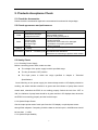
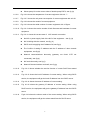
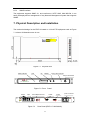
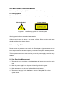
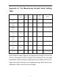
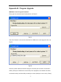
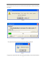
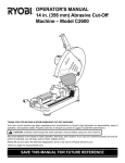
EDFA-17-220SA04G SNMP NMS Erbium-Doped Fiber Amplifier User Manual Notice: Please carefully read the User Manual before operating the product. The information contained in this manual is subject to change without notice. The EDFA (Erbium-doped fiber amplifier) described here can be used with other transmitting and receiving equipment in optical communications systems. Please strictly follow the instructions in this manual, otherwise any improper operations may unintentionally damage the product or even cause the personnel injury. EDFA is a member of Class 3B laser products. Before operating the product, the individuals must be familiar with the safety symbols on the EDFA panel and their meanings, strictly follow the instructions in chapter 8 'Laser Safety Considerations', and avoid direct laser radiation without proper safety protection. Cautions: Only trained and qualified personnel should be allowed to install, maintain, or trouble-shoot the device. Please replace the fuse with the same type, model, and trademark to avoid the fire hazards. User manual in local official languages will be provided when the product is sold to other countries where official languages are other than English. Warranty: The EDFA is warranted against defects in material and workmanship for a period of one year from date of shipment. During the warranty period, DKT will, at its option, either repair or replace products that prove to be defective. The warranty does not apply to defects resulting from improper or inadequate maintenance by users, or improper operation exceeding the environmental requirements for the products, or improper site preparation or maintenance. For warranty service or repair, this product must be returned to a service facility designated by DKT. Buyer shall pay all shipping charges, duties, and taxes for products returned to DKT. 2 Contents 1. Introduction ................................................................................................................... 4 2. Features........................................................................................................................ 4 3. Applications................................................................................................................... 5 4. Technical Specifications ................................................................................................ 5 5. Products Acceptance Check ......................................................................................... 6 5.1 Check the Accessories.................................................................................................................6 5.2 Check appearance and performance............................................................................................6 5.3 Sanity Check ...............................................................................................................................6 6. Monitoring Functionality ................................................................................................ 7 6.1 LCD Interface .............................................................................................................................7 6.2 Key Press Operation..................................................................................................................13 6.3 Parameter Checking ..................................................................................................................14 6.4 Alarm Mode ..............................................................................................................................16 6.5 Monitoring the Equipment through RJ45 Port..........................................................................17 7. Physical Description and Installation........................................................................... 25 8. Laser Safety Considerations ....................................................................................... 27 8.1 Safety Symbols .........................................................................................................................27 8.2 Laser Safety Guidance ..............................................................................................................27 8.3 Safe Operation Measurement....................................................................................................27 8.4 Training .....................................................................................................................................28 9. Maintenance and Trouble Shooting ............................................................................ 28 9.1 Maintenance ..............................................................................................................................28 9.2 Troubleshooting ........................................................................................................................29 10. Accessories List ........................................................................................................ 30 Appendix A: The Manufactory Default Alarm Setting Table ............................................. 31 Appendix B : Program Upgrade ...................................................................................... 32 3 1. Introduction An Erbium-doped fiber amplifier (EDFA) is shown in Figure 1-1. It consists of erbium-doped optical fiber, optical couplers, isolators, GFF and pump lasers etc.. An incoming optical signal (within the wavelength range of 1530nm to 1565nm) is amplified with pump lasers while traveling through a certain length of erbium-doped fiber. The amplified signal is finally coupled into four output fibers by the output connector for further transmission. The tap-couplers and detectors at input and output allow real-time monitoring of EDFA’s input and output power. The EDFA is polarization, modulation and frequency independent. All the components used in the product are built to meet Telcordia GR-1221, GR-1209 and GR-468 standards, which makes the EDFA highly reliable. Input Coupler Isolator Detector WDM EDF WDM Pump Isolator Coupler Pump Splitter Output Detector Control Unit Net Management Unit Figure 1-1 Block Diagram 2. Features z Low noise figure and wide operating wavelength range over 1530nm to 1565nm z Excellent gain and output power stability and reliability over environmental temperature of 0~50°C z Polarization, modulation and frequency independent z Low power consumption z Real-time monitor and safety alarm of operating conditions z Complies with SNMP (Simple Network Management Protocol) 4 3. Applications z z z z z Optic fiber communications networks CATV networks Computer information networks Fiber-optic sensor systems Instrumentation and equipment 4. Technical Specifications Parameters Unit Min Typ Max Note 10 total total Optical Specifications Optical input power dBm 0 4 Optical output power at each output port dBm 16.8 17 17.2 Wavelength nm 1530 1550 1564 Noise figure dB Gain flatness dB 5.0 Pin=0dBm 1.2 Based on 0dBm input power, 20°C environment temperature. PDG dB 0.3 Pump leakage at input dBm -30 Pump leakage at output dBm -30 Input Return Loss dB 45 Output Return Loss dB 45 Fiber connector SC/APC Electrical Specifications Voltage supply VAC Power consumption W Frequency Hz 100 230 240 30 50/60 Environmental Requirements Operating temperature ℃ 0 50 Storage temperature ℃ -25 70 Operating relative humidity % 5 95 Others Front panel LCD display work parameter User Interface Front panel LED display working status and alarm Network management Interface Dimension RJ45 mm3 RS232 483×252×43.6 5 (non-condensation) 5. Products Acceptance Check 5.1 Check the Accessories Please check the accessories against the accessories list enclosed in the package. 5.2 Check appearance and performance Inspection Contents Items Mechanism damage Slight deformation ● Crust ● Switch Power outlet ●Fiber adapter ●Indicator light ●Brand Coating ● ● Panel Surface Possible Defect Scratches on the surface ●Crust partial cupped ●Facial coating partial peel off ●Switch not responsive indicators ●Outlet damaged ●Protective cover break off or damaged ● Indicators not properly positioned ●Brand damaged Coating not even or peel off ● Incomplete or damaged accessories Insufficient test data sheet ●Product not conforming to product serial number ● Accessories Refer to “Accessory List” ● 5.3 Sanity Check 5.3.1 Checking Power Supply Before connecting power cable, make sure that z The voltage of the power supply is within specified range z The key is turned to OFF position z The input power is within the range specified in chapter 4 ‘Technical Specifications’ Once Switching on the power supply, the buzzer beeps and the LCD display should be working, the status indicator should be in green and the indicator of pump laser should remain dark, otherwise the EDFA is not working properly. Switch the lock from ‘OFF’ to ‘ON’, the indicator of pump laser should be in green and the LCD displays data, otherwise the EDFA is not working properly and the buzzer beeps. 5.3.2 Optical Output Power Get the output power read of each port from the LCD display or optical power-meter through fiber adapters. Comparing it with the data on the test report , the difference should be less than ±0.5dB. 5.3.3 Optical Output Stability 6 Get the output power read out from the LCD display or power-meter through fiber adapter and under the condition of stable input power, the change of output power during a short period should be less than 0.1dB. 6. Monitoring Functionality 6.1 LCD Interface 6.1.1 Boot Display Fig. 6-1.1 is displayed for around 1s, next fig. 6-1.2 around 2s. Welcome DKT Fig. 6-1.1 Company name display Initializing… Fig. 6-1.2 System initializing display 6.1.2 Parameter Search 6.1.2.1 Fig. 6-2.1 shows output optical power value of current equipment with unit dBm. Shows output power value, see fig. (a) Shows no output power, see fig. (b) 6.1.2.2 Fig. 6-2.2 shows input optical power value of current equipment with unit dBm. 6.1.2.3 6.1.2.4 6.1.2.5 Shows input power value,see fig. (a) Shows no input power, see fig. (b) Fig. 6-2.3 shows pump temperature of current equipment with unit ℃. Shows pump #1 temperature of double-pump EDFA, see fig. (a) Shows pump #2 temperature of double-pump EDFA, see fig. (b) Fig. 6-2.4 shows pump bias current value of current equipment with unit mA. Shows pump #1 bias current value of double-pump EDFA, see fig. (a) Shows pump #2 bias current value of double-pump EDFA, see fig. (b) Fig. 6-2.5 shows pump cooler current value of current equipment with unit mA. Shows pump #1 cooler current value of double-pump EDFA, see fig.(a) 7 Shows pump #2 cooler current value of double-pump EDFA, see fig. (b) 6.1.2.6 Fig. 6-2.6 shows the temperature of current equipment with unit ℃. 6.1.2.7 Fig. 6-2.7 shows the unit power consumption of current equipment with unit W. 6.1.2.8 Fig. 6-2.8 shows the model of current equipment. 6.1.2.9 Fig. 6-2.9 shows the serial number of current equipment with 10 figure. 6.1.2.10 Fig. 6-2.10 shows the version number of both firmware and hardware of current equipment. 6.1.2.11 Fig. 6-2.11 shows the current state of NIC/ network connection No NIC or power supply fault of the NIC of the equipment,see fig. (a) NIC is linking with the network, see fig. (b) DHCP service applying the IP address fail, see fig.(c) The Conflict of setting IP address and the IP address of other network equipments, see fig.(d) Network communications abnormity (gateway not found /UTP not connected), see fig.(e) 6.1.2.12 NIC work abnormity, see fig.(f) Network Communications work well, see fig.(g) Fig. 6-2.12 shows whether the service function of current DHCP has started up. 6.1.2.13 Fig. 6-2.13 shows the local IP address of current setting . When using DHCP service, the equipment will get the local IP address from the DHCP server. 6.1.2.14 Fig. 6-2.14 shows the server IP address of current setting. 6.1.2.15 Fig. 6-2.15 shows the gateway IP address of current setting. When using DHCP service, the equipment will get the gateway IP address from the DHCP server. 6.1.2.16 Fig.6-2.16 shows the subnet mask of the current setting. When using DHCP service, the equipment will get the subnet mask from the DHCP server. 8 Pout: 17.2dBm Pout: --.-dBm (a) (b) Fig. 6-2.1 Output optical power display Pin: 6.0dBm Pin: --.-dBm (a) (b) Fig. 6-2.2 Input optical power display TEMP1:25.0℃ TEMP2:25.0℃ (a) (b) Fig. 6-2.3 Pump temperature display Bias1:400mA Bias2:680mA (a) (b) Fig. 6-2.4 Pump bias current display TEC1:600mA TEC2: 1800mA (a) (b) Fig. 6-2.5 Pump cooler current display Unit TEMP: 27℃ Fig. 6-2.6 Unit temperature display Unit PWR: 16 W Fig. 6-2.7 Unit power consumption display 9 EDFA-17-220SA04G Fig. 6-2.8 Product model display S/N:8888888888 Fig. 6-2.9 Product serial number display FW:V1.1 HW:V1.0 Fig. 6-2.10 Version number of firmware and hardware No NIC NIC Link… (a) (b) DHCP Server Fail IP ADDR Conflict (c) (d) Net Link Fail NIC COMM Fail (e) (f) Net COMM OK (g) Fig. 6-2.11 Network state display DHCP Server : ON Fig. 6-2.12 DHCP service state display 10 Local IP ADDR 172.20.210.88 (a) (b) Fig. 6-2.13 Local IP address display Server IP ADDR 172.20.200.210 (a) (b) Fig. 6-2.14 Server IP ADDR display Gateway IP ADDR 172.20.200.210 (a) (b) Fig. 6-2.15 Gateway IP ADDR display Subnet Mask 172.20.200.210 (a) Fig. 6-2.16 Subnet mask display 6.1.3 (b) Alarm Display Interface Note: Buzzer in the unit will warn when below information appears on LCD,press any key to cancel。 6.1.3.1 Fig. 6-3.1 shows alarm of input optical power alarm; (a)no input,(b) low,(c) high 6.1.3.2 Fig. 6-3.2 shows alarm of output optical power alarm; (a)low,(b)high 6.1.3.3 Fig. 6-3.3 shows alarm of pump temperature alarm; (a)too low,(b)too high,(c)low,(d)high 6.1.3.4 Fig. 6-3.4 shows alarm of pump bias current alarm; (a)too high,(b)high 6.1.3.5 Fig. 6-3.5 shows alarm of pump cooler current; (a)too high,(b)high 11 No Input! Pin Too High! (a) (b) Pin Low! Pin High! (c) (d) Fig. 6-3.1 Alarm of input optical power display Pout Too Low! Pout Too High! (a) (b) Pout Low! Pout High! (c) (d) Fig. 6-3.2 Alarm of output optical power display TEMP Too Low! TEMP Too High! (a) (b) TEMP Low! TEMP High! (c) (d) Fig. 6-3.3 Alarm of pump temperature display Bias Too High! Bias High! (a) (b) Fig. 6-3.4 Alarm of pump bias current display 12 TEC Too High! TEC High! (a) (b) Fig. 6-3.5 Alarm of pump cooler current display 6.1.4 Screen Saver Interface The screen saver is made up of two parts, one of which is“Welcome DKT” (see fig 6-4.1(a)) that move from left to right, another is “█” that increase gradually from left to right(see fig 6-4.1(b)). These two parts of figures circulate again and again. ▋▋▋▋▋ lcome DKT (a) (b) Fig. 6-4.1 Screen saver display 6.2 Key Press Operation In the front panel of the unit, there are two keys (‘UP’ and ‘DOWN’ ), which is used to turn over the page for LCD menu display. The menu turns forward for one page if pressing ‘DOWN’ while the menu turns backward for one page if pressing ‘UP’. Keep pressing ‘DOWN’ or ‘UP’, the menu will keep turning forward or backward with a speed of about two pages per second. When the menu turns to the first page (Pout parameter display), it won’t turn backward if pressing ‘UP’. When the menu is in the last page (submask parameter display), it will turn to the first page (pout parameter display) if pressing ‘DOWN’. Pressing ‘UP’ and ‘DOWN’ for 5S at the same time, the systems will renew the parameter to factory setting and LCD will display ‘Restore set…. ’. Press ‘UP’ when switching on the equipment, and the NMS main control program will turn to upgrading mode. At this mode the NMS main control program can be upgrade. Pressing ‘DOWN’ when switching on the equipment, and the NMS communication program will turn to upgrading mode. At this mode the NMS communication program can 13 be upgrade. The buzzer will alarm when there is an alarm occurred. At this time pressing ‘UP’ or ‘DOWN’, the buzzer will be closed. 6.2.3 Pump Switch The indicator light will go out when the key turn to the turn off position. The system will switch to screen saver interface automatically if there is no other alarm of the current system. When the key turn to the turn on position, the pump will open and the indicator light of the pump is lightened in the following conditions. There is no firmware protection for the pump. There is no “No Input” alarm of the optical input power. 6.3 Parameter Checking 6.3.1 Checkable Parameters Parameter Display for short Unit Optical Output Power Pout dBm Optical Input Power Pin dBm Pump Temperature TEMP mA Pump Bias Current Bias mA pump cooler current TEC mA Unit Temperature Unit TEMP ℃ Unit Power Consumption Unit PWR W Equipment Model Model Serial Number S/N Version Number of FW Firmware Version Number of HW Hardware DHCP Service DHCP Server 14 Network State:Communications state of NIC and network Local IP Address:IPv4 Standard Server IP Address:IPv4 Standard Gateway IP Address:IPv4 Standard Subnet Mask:IPv4 Standard 6.3.2 Parameter Display and Instructions For the detail, please see the 6.1.2 Parameter Checking Interface. 6.3.3 Network State Indication 6.3.3.1 The meanings of network state indication is as following: No NIC or NIC power supply fault of the equipment,see fig. 6-2.11(a) NIC is linking with the network, see fig. 6-2.11 (b) DHCP service applying the IP address fail, see fig. 6-2.11 (c) The conflict of setting IP address and the IP address of other network equipments, see fig. 6-2.11 (d) Network communications abnormity (gateway not found /UTP not connected), see fig. 6-2.11 (e) 6.3.3.2 NIC work abnormity, see fig. 6-2.11 (f) Network Communications work well, see fig. 6-2.11 (g) The methods of trouble shooting (a) Checking whether there is an installed NIC or not. Checking the situation of NIC communications line/ power supply line. (b) Applying the DHCP service(0~2 minutes). Checking whether there is a conflict of IP(0~6 sec.). Inquiring the state of server (0~6 sec.). (c) Install DHCP server or cancel DHCP service function setting static IP address Keep waiting DHCP application or restart the equipment to apply again. 15 (d) Use other IP address that hasn’t been used before. Use DHCP service function to get IP address automatically. (e) Insert the network line properly/change network line. Check whether the system software of network administration in the server end work properly or not. Try to restart the equipment. (f) Try to restart the equipment. Notice: If you still can't get rid of the trouble by the above methods, please contact with the manufacturer directly. 6.4 Alarm Mode 6.4.1 EDFA Parameter Alarm and Alarm type The parameter of alarm: Optical Input Power, Optical Output Power, Pump Temperature, Pump Bias Current, Pump Refrigeration Current. Alarm type:Too Low、Low、High、Too High、No Input、No Output 6.4.2 Conditions of alarm occurred The equipment starts alarming when the current collected parameter match the pre-setting alarm scope. e.g. The optical input power low alarm is set to -6.0dBm. The alarm occurred when the collected optical input power is smaller than -6.0dBm. 6.4.3 The Condition of Alarm Restoration When the collected parameter is divorced from the alarm scope, and the divorce exceeds the pre-setting alarm sluggish value, the alarm restores (except the pump protecting alarm). e.g. The too low alarm of setting optical input power is -10dBm and the alarm sluggish value is 0.5dB. When the optical input power is no larger than -10dBm, the system starts alarming automatically. The alarm will release when then optical input power is larger than 16 -9.5dBm after the alarm. 6.4.4 Alarm Display 6.4.4.1 The alarm display interfaced have been introduced in Chapter 6.1.3. 6.4.4.2 Alarm Display/Operating z When the alarm occurs, LCD displays current alarm content automatically. (e.g. No Input) Meanwhile if there is more than one alarms occur, the alarm content displays with a alarm /5s speed roll screen automatically. z When UP or DOWN is pressed, the buzzer will stop alarming, and the LCD will shift to parameter state. If no key action is done within 10 seconds and the alarming state is not restored, the LCD will automatically shift to alarming state. 6.4.5 Pump Protecting Function In order to avoiding the damage of pump, when the following alarms occur, the system closes the pump automatically, forbids opening the pump again before shutting off the power supply, and keep the alarm, which arose the pump protecting, displaying with alarm mode (the alarm won’t disappear even when the parameter renews to normal). z Pump temperature is too high z Pump temperature is too low z Pump bias current is too high z Pump refrigeration current is too high 6.5 Monitoring the Equipment through RJ45 Port Key Words: z IP Address: The network identification number. The exclusive must be ensured, or else will lead to network disorder. z Server IP Address: The IP address of the server. z Local IP Address: The IP address of the equipment itself. z Gateway IP Address: When communications with non-local network equipment, gateway conversion is needed. z Subnet Mask: Estimate whether the IP address of objective end is in the same network segment with local IP address. If the result of((Local IP 17 objective IP) subnet mask)is the same with subnet mask, they are in the same net segment. The two IP are not in the same network segment if they are not the same and gateway conversion is needed. z DHCP Service: The service of getting local IP, gateway IP and subnet mask automatically. 6.5.1 Serial Port Setting 6.5.1.1 IP Address Setting Roles z When there is DHCP server in the network, recommend using DHCP service function in order to get local IP, gateway IP and subnet mask automatically. z When not using DHCP server, setting the local IP, gateway IP and subnet mask by hand is needed. The exclusive of local IP must be ensured, or else the device with the same IP can’t work properly. Only Setting the subnet mask correctly can make sure the device distinguish the network segment correctly. When the server and device are in the different network segment, only the correct setting of gateway IP can make sure the device communications properly. Notice: The incorrect setting IP address may lead to the communications error of other connected network devices. The incorrect gateway and subnet mask setting may also lead to the device communications improperly. Thus DHCP service function is recommended. If there is no DHCP server in the network, contacting with internal network manager before setting is needed to make sure whether there is a conflict comes from the IP address. Setup if there is no mistake. 6.5.1.2 EDFA Serial Port Setting Steps 1) Open EDFA Serial Port Setting Software named “Setup”. There will be an automatic check on whether there is a device connected to current serial interface after running the software. Fig 6-5.1(a) is displayed if there is no connected device. The device parameter is get automatically and Fig 6-5.1(b) is displayed if there is connected device. Click ‘Open’ button, the current displayed data can be refreshed. 18 (a) (b) Fig 6-5.1 EDFA serial port setup interface Notice: When Fig (a) appeared, check whether the setting of the serial port is correct first; Click ‘Setup…’ button, see Fig 6-5.2, check whether the setting of the serial port is correct or not. 19 Fig 6-5.2 Serial port setting 2) Setup IP Address: When not using DHCP service, the setting of local IP address, server IP address, gateway IP address, subnet mask is needed. The input format is showed in fig 6-5.3(a). Select ‘Using DHCP Service’ option when using DHCP service, only need to input the virtual server IP address, see fig 6-5.3(b). 20 (a) (b) 21 (c) (d) Fig 6-5.3 IP Address Setting Input the right information, click "Save". It will display "success" or "failure" at the corner of right bottom. As shown in figure 6-5.3(c)(d). 22 When IP address is successfully set,the unit will reset automatically . If failed, please press "Open " to see whether the "serial port" has been connected properly or not. If not, please recheck it or restart the device. 6.5.2 Testing network through RJ45 Port After successfully setting the equipment, and RJ45 connector in rear panel getting connected with UTP,you can test whether the network is connected. The method is as following: 6.5.2.1 Opening the MS-DOS Window of the computer (If in the Win2000 Operating Systems, click the ‘Start’ button on the left bottom, --->Program--->Accessories --->Command Prompt). Fig 6-5.4 Opening MS-DOS Window 6.5.2.2、Input ‘ping xxx.xxx.xxx.xxx’ (the local IP address of the equipment) in the MS-DOS Window. 23 6.5.2.3 If there is a prompt as follow: “Reply from xxx.xxx.xxx.xxx:bytes=32 time<10ms TTL=128” It shows that the network communications of the equipment work properly. Fig 6-5.5 Ping Command Successful 6.5.2.4、If there is a prompt as follow: “Request time out” It shows that the network communications of the equipment work by error. Fig 6-5.6 Ping Command Unsuccessful If ping command is unsuccessful, please check whether the cable connection of the equipment and the setting of the equipment IP, gateway IP, subnet mask is correct. 24 6.5.3 SNMP interface The equipment supports SNMP V1, and conforms to SCTE HMS. With MIB file, it can easily be deployed into management of any Network Management System that supports SNMP. 7. Physical Description and Installation The mechanical design for the EDFA is based on 19-inch ETS equipment rack as Figure 7-1 shows. All dimensions are in mm. Warning: 1) Ensure that the surface of the adapter and the connector are clean and dry before turning on the EDFA 2) Turn off the EDFA before cleaning, connecting or disconnecting Figure 7-1 Physical View UP LCD Status Indicator Pump Laser Indicator DOWN Pump Laser Switch OFF Erbium-Doped Fiber Amplifier PUMP STATUS UP Figure 7-2 Front DOWN Panel 10/100 Mbps Ethernet Input Output ON Welcome DKT COM1 COM2 power connector Input Output 3 Output 4 Output 2 Output 1 OFF Link Tx Rx COM2 10/100 Mbps Ethernet Figure 7-3 COM1 INPUT: 100V-230V ~ 0.5A MAX 50/60Hz Rear Panel (EDFA-17-220SA04G) 25 ON Installation Only trained and qualified personnel should be allowed to install, replace, or service this device. The EDFA can be mounted in a standard 19-inch rack. To install, please follow these steps: Step 1.Turn the EDFA chassis so that its front panel is facing you; Step 2. Determine the desired point of mounting and fix the brackets by four M6 bolts accordingly; Step 3. Attach the device to the rack with the rack mounting screws using a screwdriver. Optical Connection ______________________________________________________________ Invisible laser radiation may be emitted from the end of the unterminated fiber cable or connector. Do not stare into the beam or view directly with optical instruments. Viewing the laser output with certain optical instruments within a short distance may cause an eye hazard. Step 1. Connect the input optical fiber cable to the input connector. Avoid making sharp bends in the fiber cable; Step 2. Connect the output optical fiber cable to the output connector. Avoid making sharp bends in the fiber cable. AC Power Connection Step 1. Connect the device with a AC power source; Step 2. Apply AC power; Step 3. Switch on the device. 26 8. Laser Safety Considerations Erbium-Doped Fiber Amplifier (EDFA) is a member of Class 3B laser products. 8.1 Safety Symbols The direct laser radiation to skin and eyes may cause personnel injury, even eyes blindness. Warning Symbol Figure 8-1 Caution Symbol Laser Warning Symbol and Caution Symbol Warning symbol indicates harzardous laser radiation. Caution symbol means this device is a member of Class 3B laser products and users should avoid direct laser beam radiation. 8.2 Laser Safety Guidance Do not remove the protective cover outside the fiber adapter or jumper connector at the EDFA output port until it has been completely connected to the system or test equipments. This is to prevent personnel or eyes from injury in case the power supply is switched on by accident. 8.3 Safe Operation Measurement 1. The protective cover should be on the fiber adapter and jumper connector when not in use. 2. When the power supply is on, the power indicator light should be green. 3. When pump laser is on, the pump indicator light should be green. 4. The personnel engaged in the installation or service of the optical fiber cable or system should: 27 – observe all rules, procedures and practices established for the safe operation of optical fiber communication systems; – immediately notify the supervisor of conditions or practices that have the potential to cause personnel injury or property unintended damage; – immediately report to the supervisor any known or suspected abnormal exposure to laser radiation. The direct laser contact to skin and eyes may cause human body injury, even blindness. 8.4 Training 1. The operator should be trained to have a clear understanding of the background information on optical fiber communication systems; 2. The operator should understand that the EDFA is a member of Class 3B laser products. The safety information and safety practices in Chaper 8 must be strictly followed by the operator. Pay special attention to the laser classification system and hazard levels, avoid direct laser contact to either skin or eyes. 9. Maintenance and Trouble Shooting 9.1 Maintenance At any rate, please avoid direct eye face to the input/output port of fiber connector in case of any injury of eyes and skin. Make sure the EDFA is switched off before taking away the fiber connector at the output port. Do not turn on the EDFA without coupling with the optical fiber connector. Cleaning connectors The procedures in this section provide the proper steps for cleaning fiber cables and adapters. The initial cleaning, using the alcohol as a solvent, gently removes any grit and oil. If a caked-on layer of material is still present, a second cleaning should be performed. It is not uncommon for a cable or connector to require more than one cleaning. 28 To clean a connector 1. Apply alcohol (IPA) to a clean lint-free cotton swab or lens paper. Cotton swabs can be used as long as no cotton fibers remain on the fiber end after cleaning. 2. Clean the ferrules and other parts of the connector while avoiding the end of the fiber. 3. Apply alcohol (IPA) to a new clean lint-free cotton swab or lens paper. 4. Clean the fiber end with the swab or lens paper. Do not scrub during this initial cleaning because grit can be caught in the swab and become a gouging element. 5. Immediately dry the fiber end with a clean, dry, lint-free cotton swab or lens paper. 6. Blow across the connector end face from a distance of 6 to 8 inches using filtered, dry, compressed air. Aim the compressed air at a shallow angle to the fiber end face. Nitrogen gas or compressed dust remover can also be used. 7. As soon as the connector is dry, connect or cover it for later use. If the performance after the initial cleaning seems poor, try cleaning the connector again. Often a second cleaning will restore proper performance. The second cleaning should be more arduous with a scrubbing action. To clean an adapter 1. Apply alcohol (IPA) to a clean foam swab. Cotton swabs can be used as long as no cotton fibers remain after cleaning. The foam swabs listed in this section’s introduction are small enough to fit into adapters. Although foam swabs can leave filmy deposits, these deposits are very thin, and the risk of other contamination buildup on the inside of adapters greatly outweighs the risk of contamination by foam swabs. 2. Clean the adapter with the foam swab. 3. Dry the inside of the adapter with a clean, dry, foam swab. 4. Blow through the adapter using filtered, dry, compressed air. Nitrogen gas or compressed dust remover can also be used. 9.2 Troubleshooting This section discusses basic fault investigation and diagnostic (troubleshooting) procedures for EDFA. 29 Alarm Status Cause Pump Chip Input Output Actions Temperature z z z Pump chip temperature abnormal Check ambient temperature Pump chip temperature abnormal Check ambient temperature z Input power out of range Input connector failed Clean fiber connector Check input signal power z z Input power or wavelength out of range; input connector defective Clean fiber connector Check input signal power Ask for technical support z Input wavelength out of range or optical module defective Check signal wavelength and signal power Only trained and qualified personnel should be allowed to perform troubleshooting task to avoid any unintended further damages. Please read carefully the following tables to perform troubleshooting tasks. Multiple alarms could happen at the same time and some analysis maybe required to diagnose the root causes of the faults. For further technical support, please contact a service facility designated by DKT. 10. Accessories List NO. Contents Quantity 1 Power Cord 1 2 Pump Laser Switch Key 1 3 Optical Fiber Jumper(SC/APC) 4 4 RS-232 Port Cable 1 5 Fuse Tube (2A) 2 6 User Manual 1 7 Testing Report 1 30 Remark Appendix A: The Manufactory Default Alarm Setting Table Optical Input Power (dBm) Too Alarm Low Renew Alarm Sluggish -6.0 -10.0 0.3 25.0 11.0 ----- 0.5 30 28 22 20 1 1000 ----- ----- ----- 50 1200 ----- ----- ----- 50 30 28 22 20 1 1000 ----- ----- ----- 50 1200 ----- ----- ----- 50 Too High High Low Alarm Alarm Alarm ----- 10.0 ----- Remark Optical Output Power (dBm) Pump #1 Temperature (℃) Pump #1 Bias Current (mA) Pump #1 Cooler Current (mA) Pump #2 Temperature (℃) Pump #2 Bias Current (mA) Pump #2 Cooler Current (mA) 2500mA (EDFA-17-220SA04S) Notice: When the alarm of pump #1, #2 temperature is too high or too low, bias current or refrigeration current is too high occurs, the firmware closes the pump automatically, forbids opening the pump again before shutting off the power supply, and keep the alarm that arose the pump protecting. All the alarm of optic output power will be renewed after close the pump. 31 Appendix B : Program Upgrade NMS Main Control Program Download Firstly open the download tools Download.exe, see Fig.B-1. Fig.B-1 Then click ‘Browse’ to choose the download file of NMS main control program code, see Fig.B-2. Fig.B-2 After that, please make sure that the serial port connecting line has been connected to COM1 (serial port of NMS main control PCB) of the equipment, the hardware has been connected correctly and the serial port setting is correct (serial port can be set by ‘Setup’). 32 Click ‘Download’, then click ‘yes’ in the confirm window (see Fig.B-3), it starts downloading, see Fig.B-4. Fig.B-3 Fig.B-4 The system shows that download success when finished, see Fig.B-5. Fig.B-5 If it appears the window like Fig.B-6 when starting downloading, it shows that the selected 33 file doesn’t match the connected serial port and the selected file is not the program file of NMS main control PCB. Fig.B-6 NMS Communication Program Download The download of NMS communication program is nearly the same as NMS main control program. Please also note that the connecting line must be connected to COM2 (the serial port of NMS communication PCB) of the equipment before upgrading the NMS communication program. 34