1
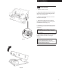
Please leave these instructions with the user
BaxiSolo 2 PF
Wall Mounted Powered Flue
Gas Fired Central Heating Unit
Installation and
Servicing Instructions
Natural Gas
Baxi Solo 2 30 PF
G.C.No. 41 077 71
Baxi Solo 2 40 PF
G.C.No. 41 077 72
Baxi Solo 2 50 PF
G.C.No. 41 077 73
Baxi Solo 2 60 PF
G.C.No. 41 077 74
Baxi Solo 2 70 PF
G.C.No. 41 075 01
Baxi Solo 2 80 PF
G.C.No. 41 077 75
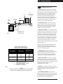
Baxi Heating Ltd is one of the leading manufacturers
of domestic heating products in the UK.
Our first priority is to give a high quality service to our
customers. Quality is built into every Baxi product products which fulfil the demands and needs of
consumers, offering choice, efficiency and reliability.
To keep ahead of changing trends, we have made a
commitment to develop new ideas using the
latest technology - with the aim of continuing to
make the products that customers want to buy.
Baxi is also the largest manufacturing partnership in
the country. Everyone who works at the company
has a commitment to quality because, as
The boiler meets requirements of Statutory
Instrument “The Boiler (Efficiency) Regulations
1993 No 3083” and is deemed to meet the
requirements of Directive 92/42/EEC on the
efficiency requirements for new hot water boilers
fired with liquid or gaseous fuels:-
shareholders, we know that satisfied customers
mean continued success.
We hope you get a satisfactory service from Baxi. If
not, please let us know.
Baxi is a BS-EN ISO 9001
Accredited Company
2
Type test for purpose of Regulation 5 certified by:
Notified Body 0086.
Product/Production certified by:
Notified Body 0086.
Contents
Section
Page
1.0
Introduction
4
2.0
Technical Data
5
3.0
System Details
7
4.0
Site Requirement
10
5.0
Installation
13
6.0
Commissioning the Appliance
31
7.0
Fitting the Outercase
33
8.0
Overheat Cut-Off Device
34
9.0
Annual Servicing
35
8.0
Changing Components
37
9.0
Short Parts List
41
10.0 Fault Finding
42
3
1.0 Introduction
1.1
Description
1. The Baxi Solo 2 PF is a gas fired room sealed
fan assisted central heating boiler with range rated
outputs as shown in the table below
Model
30
40
50
60
70
80
Min
HEAT OUTPUT
Max
5.86kW (20,000 Btu/h)
9.09kW (31,000 Btu/h)
12.02kW (41,000 Btu/h)
14.95kW (51,000 Btu/h)
17.88kW (61,000 Btu/h)
20.8kW (71,000 Btu/h)
8.79kW (30,000 Btu/h)
11.72kW (40,000 Btu/h)
14.65kW (50,000 Btu/h)
17.58kW (60,000 Btu/h)
20.5kW (70,000 Btu/h)
23.45kW (80,000 Btu/h)
2. Each appliance is preset at a MID RANGE heat
input rating and is designed for use on NATURAL
GAS only.
3. All boilers are suitable for fully pumped open
vented central heating and domestic hot water
systems and sealed systems.
4. The appliance data badge is fitted to the
combustion box door.
1.2
Installation
1. The appliance is suitable for installation only in
G.B. and I.E. and should be installed in
accordance with the rules in force. For Ireland
install in accordance with I.S.813 “INSTALLATION OF
GAS APPLIANCES”. The installation must be carried
out by a CORGI Registered Installer or other
competent person and be in accordance with the
relevant requirements of GAS SAFETY (Installation
and Use) REGULATIONS, the BUILDING REGULATIONS
(Scotland) (Consolidation), the LOCAL BUILDING
REGULATIONS, the CURRENT I.E.E. WIRING
REGULATIONS and the bye laws of the Local Water
Undertaking. Where no specific instructions are
given, reference should be made to the relevant
BRITISH STANDARD CODES OF PRACTICE.
2. All systems must be thoroughly flushed and
treated with inhibitor (see Section 3.1).
1.3
B.S. Codes of Practice
STANDARD
SCOPE
B.S. 6891
Gas Installation.
B.S. 5546
Installation of hot water supplies for
domestic purposes.
B.S. 5449
Forced circulation hot water systems.
B.S. 6798
Installation of gas fired hot water
boilers.
4
B.S. 5440: Pt 1
Flues.
B.S. 5440: Pt 2
Ventilation.
Important Information
This product contains Refractory Ceramic Fibres
(R.C.F.) which are man-made vitreous silicate
fibres. Excessive exposure to these materials may
cause tempory irritation to eyes, skin and
respiratory tract. Care must be taken when
handling these articles to ensure the release of
dust or fibres is kept to a minimum.
To ensure that the release of fibres from these
articles is kept to a minimum, during installation
and servicing it is recommended that a H.E.P.A.
filtered vacuum is used to remove any dust, soot
or other debris accumulated in and around the
appliance. This should be performed before and
after working on the installation.
It is recommended that any replaced item(s) are
not broken up but sealed within heavy duty
polythene bags and clearly labelled “R.C.F.
waste”. This is not classified as “hazardous waste”
and may be disposed of at a tipping site licensed
for the disposal of industrial waste.
Protective clothing is not required when handling
these articles but it is recommended that gloves
are worn and the normal hygiene rules of not
smoking, eating or drinking in the work area are
followed and always wash hands before eating or
drinking.
1
2.0 Technical Data
Model
30
40
50
60
70
80
kW
8.9
11.72
14.65
17.58
20.5
23.45
Btu/h
30,000
40,000
50,000
60,000
70,000
80,000
kW
5.86
9.09
12.02
14.95
17.88
20.8
Btu/h
20,000
31,000
41,000
51,000
61,000
71,000
kW
10.99
14.65
18.32
21.98
25.64
29.31
Btu/h
37,500
50,000
62,500
75,000
87,500
100,000
kW
7.33
11.36
15.02
18.68
22.35
26.01
Btu/h
25,000
38,750
51,250
63,750
76,250
88,750
mbar
16.0 ±0.5
16.0 ±0.5
16.0 ±0.5
16.0 ±0.5
16.0 ±0.5
16.0 ±0.5
in wg
6.4 ±0.2
6.4 ±0.2
6.4 ±0.2
6.4 ±0.2
6.4 ±0.2
6.4 ±0.2
mbar
8.0 ±0.5
10.0 ±0.5
11.5 ±0.5
11.5 ±0.5
12.1 ±0.5
11.5 ±0.5
in wg
3.2 ±0.2
4.0 ±0.2
4.4 ±0.2
4.4 ±0.2
4.8 ±0.2
4.4 ±0.2
CV 38MJm3
1.04m3/h
1.39m3/h
1.74m3/h
2.08m3/h
2.78m3/h
2.78m3/h
36.86ft3/h
49.0ft3/h
61.3ft3/h
73.5ft3/h
98.1ft3/h
98.1ft3/h
kg
23.1
23.1
23.1
32.2
32.2
34.2
lbs
51
51
51
71
71
75.5
litres
1.1
1.1
1.1
1.6
1.6
1.3
pints
1.9
1.9
1.9
2.8
2.8
2.3
Outercase
Height
600mm
600mm
600mm
600mm
600mm
600mm
Dimensions
Width
350mm
350mm
350mm
462mm
462mm
462mm
Depth
287mm
287mm
287mm
287mm
287mm
287mm
Heat Output (Max)
Heat Output (Min)
Heat Input (Max)
Heat Input (Min)
Burner Pressure (Max)
Burner Pressure (Min)
Gas Rate
(after 10 mins)
Lifting Weight
Water Content
Flue Terminal
Diameter
100mm
Dimensions
Depth
65mm
Static Head
Max
30 metres (100 ft)
Min
1 metres (3.25 ft)
Flow
22mm Cu tail
Return
22mm Cu elbow
Connections
Heat Exchanger
Low Head
Cast iron monobloc
Min
0.2m (8 in)
System Design
fully pumped open vented and sealed systems
Gas Connection
RC1/2 (1/2 in BSPT)
Electrical Supply
230V ~ 50Hz fused 5A - 90W
Controls
boiler thermostat, pilot & electronic flame sensing, timed pump over-run,
frost protection thermostat
Internal Fuse
1
4AF 250V to BS4256 situated on control board
5
2.0 Technical Data
(52) 130
(48) 120
(44) 110
(40) 100
(36) 90
(32) 80
(28) 70
(24) 60
(20) 50
(16) 40
(12) 30
(8) 20
(4) 10
Pressure Drop mbar (in wg)
Pressure Drop mbar (in wg)
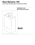
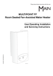
Hydraulic Resistance Charts
(52) 130
(48) 120
(44) 110
(40) 100
(36) 90
(32) 80
(28) 70
(24) 60
(20) 50
(16) 40
(12) 30
(8) 20
(4) 10
2 4 6 8 1012 1416 18 2022 242628 30
2 4 6 8 1012 1416 18 2022 242628 30
Water Flow Rate litres / min
Water Flow Rate litres / min
60, 70 and 80 PF models
30, 40 and 50 PF models
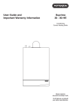
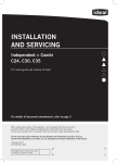
Templates
25
268
75
107 Dia
without
internal
fitting
117 Dia
with
internal
fitting
75
121
107 Dia
without
internal
fitting
392
439
442
Centre of
Gas Connection
144
4
144
25
380
117 Dia
with
internal
fitting
392
439
442
Centre of
Gas Connection
8 Slots
20 x 6
8 Slots
20 x 6
52
196
196
Layout of Fixing Points
60, 70 and 80 PF models
Layout of Fixing Points
30, 40 and 50 PF models
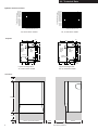
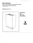
Clearances
50mm
600mm
100mm
5mm
6
121
350mm (30,40,50 models)
462mm (60,70,80 models)
5mm
287mm
300mm for servicing
5mm during operation
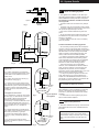
3.0 System Details
3.1
Option B
1. The appliance is suitable for use with open
vent fully pumped systems, sealed systems and
where additional control protection is required.
The following conditions should be observed
on all systems:
Option C
Radiator
Circuit
Fig. 1
Water Circulating Systems
• The static head must not exceed 30m (100ft) of
water.
• The boiler must not be used with a direct cylinder.
• The boiler is fitted with a timed pump overrun that
will operate for approximately 8 minutes.
• Drain cocks should be fitted to all system low
points.
• All gas and water pipes and electrical wiring must
be installed in a way which would not restrict the
servicing of the boiler.
• Position isolating valves as close to circulating
pump as possible.
Air Vent
Treatment of Water Circulating Systems
Pump
Radiator
Circuit
Option A
Boiler
Fig. 2
Fully Pumped System
Examples of systems which require a
bypass are:Air
Vent
a) A system controlled by non-electrical
valves e.g. mechanical thermostatic control
valves both on the radiators and the hot
water circuit.
b) A system using twin zone valves (e.g.
Honeywell 'S' Plan) (Fig. 3).
c) A system using a 3 port divertor valve
(Fig. 4) does not normally require a bypass
therefore this system is recommended. The
exception to this is where thermostatic
radiator valves are used and then a bypass
is required.
Radiator
Circuit
Twin Zone
Valve System
The bypass circuit can be:a) For 30/40/50 PF a minimum of 8 metres
of 22mm pipe, for 60/70/80 PF a minimum
of 8 metres of 28mm pipe (measured
between the boiler flow and return
connections). It should be fitted with a lock
shield valve opened at least 1 full turn to
give a minimum flow rate of 8 litres/min (1.8
gal/min) (Option C, Fig. 1 & Option A,
Fig.2).
Typical Systems
Arrangement
Fig. 3
• All recirculatory water systems will be subject to
corrosion unless an appropriate water treatment is
applied. This means that the efficiency of the system
will deteriorate as corrosion sludge accumulates
within the system, risking damage to pump and
valves, boiler noise and circulation problems.
• For optimum performance after installation this
boiler and its associated central heating system
must be flushed in accordance with the guidelines
given in BS 5793:1992 “Treatment of water in
domestic hot water central heating systems”.
• This must involve the use of a proprietary
cleanser, such as BetzDearborn Sentinel X300 or
X400, or Fernox Superfloc. Full instructions are
supplied with the products, but for immediate
information please contact BetzDearborn (0151 420
9563) or Fernox (01799 550 811) directly.
• For long term protection against corrosion and
scale, after flushing it is recommended that an
inhibitor such as BetzDearborn Sentinel X100, or
Fernox MB-1 or Copal is dosed in accordance with
the guidelines given in BS 5793:1992.
Failure to flush and add inhibitor to the system
may invalidate the appliance warranty.
• It is important to check the inhibitor concentration
after installation, system modification and at every
service in accordance with the manufacturer’s
instructions. (Test kits are available from inhibitor
stockists.)
• For information or advice regarding any of the
above contact the Baxi Helpline.
3.2
Air
Vent
Bypass Requirements
1. The boiler is fitted with a pump overrun device
which allows the removal of residual heat from
the boiler.
b) A radiator fitted with lock shield valves.
The radiator output should be a minimum of
800 watts (2,700 Btu/h). Typically a
convector type radiator with an area of
3750 cm2 (4 sq ft) is adequate (Option B,
Fig. 1).
Radiator
Circuit
c) Any circuit that provides the same
operating conditions as option A or option B
(Figs. 1 & 2).
NOTE: The pump overrun will operate for
approximately 8 minutes. The system design
must therefore, always provide an open circuit for
water to circulate between the boiler flow and
return.
3 Port Divertor
Valve System
Fig. 4
7
3.0 System Details
3.3
mm
500
22mm
Open Vent
45°
1000mm
Min
15mm
Cold
Feed
1. The sizes of flow and return pipes from the
boiler should be determined by normal methods,
according to the requirements of the system.
2. An 11 °C (20°F) drop in temperature across the
system is recommended.
400mm
Min Head
3.4
150mm
Max
Boiler
Pipework
System Controls
1. For optimum operating conditions, the heating
system into which the boiler is installed should
include a control system.
Pump
Flow
2. Such a system will comprise of a timer control
and separate room or cylinder thermostats as
appropriate.
Return
Fig. 5
Typical Low Head Installation
mm
500
3. The boiler should be controlled so that it
operates on demand only.
4. Operation of the system under control of the
boiler thermostat only does not produce the best
results.
22mm
Open Vent
5. A frost thermostat is fitted integrally to the
appliance controls and will protect the boiler from
frost damage by operating the burner when the
water temperature in the boiler drops towards
freezing point. The boiler will fire as necessary to
maintain a temperature above freezing.
45°
Automatic
Air Vent
15mm
Cold
Feed
1000mm
Min
Boiler
400mm
Min Head
150mm
Max
Pump
Flow
Return
Fig. 6
If Conditions Require,
This System Possible
NOTE: The frost thermostat operates even if
the boiler thermostat is in the OFF ('0') position
and it is necessary therefore, if the system is
drained, for the external electrical and gas
supplies to be isolated. It is recommended that
a label be affixed to the appliance to draw
attention to the fact that the system has been
drained.
3.5
Low Head Installation
For boilers up to 50,000 Btu/h output
1. Using a close couple arrangement the minimum
head is as shown in the diagrams (Figs. 5 & 6)
subject to the following conditions:
200mm
Min
22mm
Feed & Vent
Pipe
Air
Separator
Boiler
Pump
Flow
Return
a) The correct heat input.
b) The pump being adjusted to give an 11oC
drop across the boiler.
c) The pump must be fitted on the flow.
d) The pump must be fitted in accordance with
the pump manufacturer's instructions.
e) The open vent pipe must be taken up from a
tee in a horizontal section of the flow pipe.
Alternative Low Head Installation for all Solo 2 PF
(Fig. 7)
Fig. 7
8
Alternative Low Head Installation
2. If less height is available then a combined vent
and feed pipe may be connected. This must be a
minimum of 22mm diameter. It is recommended
that an air separator is fitted when using a
combined feed and vent pipe.
3.0 System Details
3.6
3 Litre
Top Up Bottle
(if required)
Air
Vent
Pressure
Gauge
Safety
Valve
Filling
Point
Sealed Systems (Fig. 8)
1. SAFETY VALVE - A safety valve complying
with the requirements of BS 6750 Part 1 must be
fitted close to the boiler on the flow pipe by means
of a horizontal or vertically upward connection
with no intervening valve or restrictions and
should be positioned to facilitate testing. The
valve should be pre-set and non-adjustable to
operate at a pressure of 3 bar (45 Ibf/in2). It must
be arranged to discharge any water or steam
through a pipe to a safe outlet position.
Pump
Radiator
Circuit
Expansion
Vessel
Boiler
System Drains
at Low Point
3. EXPANSION VESSEL - An expansion vessel
complying with the requirements of BS 4814 must
be fitted to the system by means of a connection
close to the inlet side of the circulating pump in
accordance with the manufacturers instructions,
the connecting pipe being unrestricted and not
less than 15mm (1/2 in) nominal size. The volume
of the vessel should be suitable for the system
water content and the nitrogen or air charge
pressure should not be less than the system static
head (See Table. 1).
Max Boiler Flow
Temp = 82° C
Fig. 8
Further details of sealed system design can be
obtained from BS 5449 and the British Gas
publication entitled 'Specifications for Domestic
Wet Central Heating Systems'.
Method of determining minimum
value of expansion vessel volume for
sealed systems using Baxi Boilers
Vessel Charge
Pressure (Bar)
Initial System
Pressure (Bar)
0.5
1.0
1.5
2.0
1.0
1.5
2.0
1.5
2.0
0.5
1.0
1.5
2. PRESSURE GAUGE - A pressure gauge of
minimum range 0-4 bar (0-60 Ibf/in2) with a fill
pressure indicator must be fitted to the system,
preferably at the same point as the expansion
vessel in an easily visible position.
Multiply Total
Water Content Of
System By (Litres)
0.067
0.112
0.207
0.441
0.087
0.152
0.330
0.125
0.265
System Volume = 75 litres
Vessel Charge Pressure = 1.0 bar
Initial System Pressure = 1.5 bar
Then :- 75 x 0.152 = 11.4 litres
Expansion Vessel Volume
Example :-
Table. 1
NOTE
Where a vessel of the calculated size is not obtainable
then the next available larger size should be used.
4. FILLING POINT - A filling point and an
approved stop valve to BS 1010 must be fitted at
low level and the method used for filling the
system should be approved by the local water
undertaking. For further details see BS 6798.
5. MAKE UP SYSTEM - A method of replacing
water lost from the system should be provided
either by means of a make up vessel of not more
than 3 litres (5 pints) capacity, mounted above the
highest point of the system, or by prepressurisation of the system.
6. VENTING - A method of venting the system
during filling and commissioning must be provided
by fitting automatic air vents or by venting
manually.
7. HOT WATER STORAGE - The hot water
storage vessel must be of the indirect coil type. All
components used in the system must be suitable
for operation at 110°C (230°F) and at the
pressure allowed by the safety valve.
9
4.0 Site Requirements
4.1
Location
1. The appliance may be fitted to any suitable wall
with the flue passing through an outside wall and
discharging to atmosphere in a position permitting
satisfactory removal of combustion products and
providing an adequate air supply (Fig. 9). The
appliance should be fitted within the building unless
otherwise protected by a suitable enclosure ie.
garage or outhouse. (The appliance may be fitted
inside a cupboard. Cooling ventilation and insulation
of the cupboard are not required, see section 4.5.)
2. If the appliance is fitted in a room containing a bath
or shower reference must be made to the Current
I.E.E. Wiring Regulations and Building Regulations. If
the appliance is to be fitted into a building of timber
frame construction then reference must be made to
British Gas document DM2.
Fig. 9
Model
30
40
50
60
70
80
A
350
350
350
462
462
462
3. Recommendations for flues are given in BS 5440
Part 1.
4.2
5
A
5
50
300
Clearances (Fig. 10)
1. A flat vertical area is required for the installation of
the boiler measuring as shown in the table below for
each model.
Width
Model Height
mm (in)
mm (in)
30
750 (291/2) 360 (141/8)
40
750 (291/2) 360 (141/8)
50
750 (291/2) 360 (141/8)
60
750 (291/2) 472 (185/8)
70
750 (291/2) 472 (185/8)
80
750 (291/2) 472 (185/8)
2. These dimensions include the necessary
clearances around the appliance for case removal,
spanner access and air movement. Additional
clearances may be required for the passage of pipes
around local obstructions such as joists running
parallel to the front face of the appliance.
600
Fig. 10
3. If fitted inside a cupboard the clearance of 300mm
shown is only necessary when the cupboard door is
open. A clearance of 5mm (3/16 in) is required when
the door is closed.
100
4.3
Flue Position
1. For installations where the flue terminal is
inaccesible from the outside, an internal fitting kit is
available. This can be obtained free of charge from
your local merchant.
2. The following guide lines indicate the general
requirements for siting balanced flue terminals.
Aluminium
Shield
3. If the terminal is fitted within 1 metre (39in) of a
plastic gutter, within 500mm (191/2 in) of a painted
eave or a painted gutter, an aluminium shield of at
least 1 metre (39in) long should be fitted to the
underside of the gutter or painted surface. An air
space of 5mm (3/16 in) should be left between shield
and gutter (Fig. 11).
4. If the terminal discharges onto a pathway or
passageway, check that combustion products will not
cause a nuisance and that the terminal will not
obstruct the passageway.
10
Fig. 11
5. If the outer surface of an outside wall is of
combustible material, it should be protected by fitting
the flue trim provided.
4.0 Site Requirements
4.3
Flue Position (Cont)
WARNING - The addition of anything that may
interfere with the normal operation of the
appliance (e.g. FLUE DAMPERS,
ECONOMISERS,etc.) without the express
written permission of Baxi Heating Ltd could
invalidate the appliance warranty and infringe
the GAS SAFETY (Installation and Use)
REGULATIONS.
B,C
K
J
G
G
D
F
H,I
A
L
If a terminal is less than 2 metres (783/4 in)
above a balcony, above ground or above a flat
roof to which people have access then a
suitable terminal guard must be provided.
D
6. Table 2 and the accompanying diagram show
the positioning of the flue terminal relative to
buildings and other structures.
F
A
E
G
Likely positions requiring
a flue terminal guard
7. The dimensions of the flue terminal are shown
in Fig. 12.
4.4
Terminal Position with Minimum Distance
Directly below an openable window or other
opening, e.g. an air brick.
B Below gutters.
C Below eaves, soil pipes or drain pipes.
D Below balconies or car port roof
E From vertical drain pipes and soil pipes.
F From internal or external corners.
G Above ground, roof or balcony level.
H From a surface facing a terminal.
I From a terminal facing a terminal.
J Vertically from a terminal on the same wall.
K Horizontally from a terminal on the same wall.
L For an opening in a car port (e.g. door, window)
into a dwelling.
A
Table. 2
Flue Dimensions
(mm)
300
25
75
200
75
25
300
600
1200
1500
300
1200
1. The standard flue supplied with the appliance
is suitable for use with flue lengths between
100mm (4in) and 685mm (27in).
NOTE: Maximum flue length when flued to the
left or right is
584mm (23in) - 30, 40, 50 PF
533mm (21in) - 60, 70, 80 PF
2. Flue extension kits are available as an optional
extra for installations up to 1 metre
(393/8 in) and up to 2 metres (793/4 in). 2 metre kit
is not available for the 70 and 80 PF model.
3. A vertical flue kit, with flue breaker, is also
available as an optional extra (Sol-Ver Kit).
4. Where it is intended to pass the flue through a
combustible wall or timber framed dwelling,
reference should be made to British Gas
publication DM2.
5. If the flue is more than 1.8 metres (707/8 in)
long, it is required that it is supported.
65
6. All above dimensions are taken from the
respective faces of of the outer case.
100
Flue Terminal Dimensions
Fig. 12
11
4.0 Site Requirements
4.5
Ventilation of Compartments
1. Where the appliance is installed in a cupboard
or compartment, no air vents are required.
NOTE: The ventilation label on the front of the
outer case MUST NOT BE REMOVED when
the appliance is installed in a compartment or
cupboard.
2. B.S. 5440 Part 2 Clause 4.2 refers to room
sealed appliances installed in compartments.
The Solo 2 PF will run sufficiently cool without
ventilation.
4.6
Gas Supply (Fig. 13)
1. The gas installation should be in accordance
with BS 6891.
2. The connection of the appliance is a RC1/2 (1/2
in BSPT internal) located at the rear of the gas
cock.
3. Ensure that the pipework from the meter to the
appliance is of adequate size. Do not use pipes
of a smaller diameter than the appliance gas
connection.
4.7
Electrical Supply
Fig. 13
External wiring must be correctly earthed,
polarized and in accordance with CURRENT
I.E.E. WIRING REGULATIONS.
The mains supply is 230V ~ 50Hz fused at 5A.
NOTE: The method of connection to the
electricity supply must facilitate complete
electrical isolation of the appliance.
Connection may be made via a fused doublepole isolator with a contact separation of a least
3mm in all poles and serving the appliance and
system controls only.
12
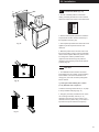
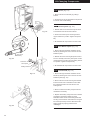
5.0 Installation
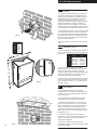
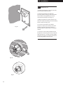
5.1
Initial Preparation
1. Unpack contents of carton.
2. Remove the lower door panel from the outer
case. Remove the 2 screws holding the outer
case to the combustion box.
3. Place the ready assembled outer case in a
safe place until required.
4. Release the R clips from the two latches
securing the combustion box to the back plate
and release the latches (Fig. 14).
5. Lift and remove the combustion box from the
back plate (Fig. 15). Place the combustion box
on its back.
IMPORTANT - When installing a Solo 2 with
a rear flue see section 5.2 before continuing
the installation.
6. Proceed to the relevant section for flueing the
appliance either to the Rear, Left, Right or
Vertically.
Fig. 14
NOTE: For Vertical flueing or flue lengths
above the standard 610mm (24 in) the
relevant optional extra kits must be obtained
and their instructions followed.
Fig. 15
13
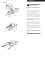
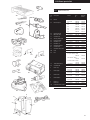
5.0 Installation
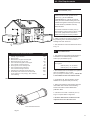
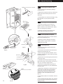
5.2
Fan Outlet Restrictor
(30, 40, 50, 60, 70 and 80)
Rear Flue only up to 686mm (27 in)
Fig. 16a
Fig. 17
1. Release the four latches holding the
combustion box door (Fig 16a). Remove the
combustion box door by pulling forward from the
bottom and unhooking its top edge (Fig. 16).
2. Release the 5-pin electrical plug connecting
the pressure switch and fan (Fig. 17). Withdraw
the fan assembly by pulling forwards from the
top edge (Fig. 16).
3. Take the sheetmetal restrictor (supplied in the
kit of parts), check that the number stamped on
the restrictor matches the appliance (e.g. 50
stamped on the restrictor is for 50 PF appliance)
4. Fit the restrictor to the fan outlet flange,
bending the 3 lugs equally over the flange to
secure (Fig. 18).
5. Re-assemble the fan assembly and
combustion box door.
Fig. 16
Fan Outlet Flange
Fan Outlet Restrictor
Fig. 18
14
5.0 Installation
A
50
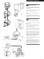
5.3
Position the Boiler (Fig. 19)
1. Choose a suitable position for the boiler
making necessary allowances for the minimum
clearances required as shown in the table below.
750
Model
30
40
50
60
70
80
100
A
360
360
360
472
472
472
2. Hold the wall template against the wall at the
required boiler location. Ensure that the top of
the template is level (Fig. 20).
Fig. 19
3. The template represents the outer limits of the
appliance plus the required minimum side
clearance.
4. Mark the position of the flue hole centre and
the inward pointing corners of the two triangular
cutouts in the template. Mark the position of the
four fixing holes. Where possible use the
uppermost and lowest fixing hole positions,
otherwise space the fixing holes as far apart as
possible (Fig. 20).
5.4
Fig. 20
Rear Flue
1. For installations where the flue terminal is
inaccessible from the outside, an internal fitting
kit is available. This can be obtained free of
charge from your local merchant quoting Baxi
Part No 226441.
2. If using the internal fitting kit a 117mm
(45/8 in) diameter hole is required.
3. Drill the anchorage holes 63mm (21/2 in) deep
to accept suitable wall plugs (Fig. 21).
4. Using the previously marked flue hole centre,
cut a hole approximately 107mm (41/4 in)
diameter in the masonry for the 100mm (4 in)
diameter flue duct. (When using a core drill, it is
important to keep the drill level and square).
Fig. 21
15
5.0 Installation
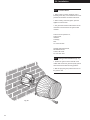
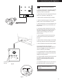
5.5
Rear Flue Preparation
1. Measure the wall thickness (Fig. 22) and to this
dimension add 60mm (23/8 in).
Wall Thickness
2. Take the flue duct and mark off wall thickness
+ 60mm (23/8 in) from the swaged end of the duct
and cut to size (Fig. 23). (Use the tape provided
to give an accurate cutting guide by wrapping it
around the flue duct with the edge marking the
cutting line).
Fig. 22
3. Wall Thickness 280mm - 685mm
(11in - 27in) -Take the telescopic air duct from its
pack. Open the air duct out to the wall thickness.
Using the tape provided seal the joints of the
three sections of the air duct, ensuring an overlap
of at least 30mm (13/16 in) at each joint (Fig. 24).
Wall Thickness + 60mm
Fig. 23
NOTE: The seams of all three sections must
be in line.
4. Wall Thickness 100mm - 280mm (4in - 11in)
If the wall thickness is less than 280mm (11 in), it
will be necessary to cut the components of the air
duct to the appropriate size. Dispose of the centre
section, as this is not required (Fig. 25).
5. Measure the wall thickness and subtract 30mm
(13/16 in) from this dimension. Cut the remaining
sections to this length, measuring from the
positions indicated in the diagram (Fig. 25).
6. Engage the sections, one inside the other, then
open the assembly out to wall thickness. Tape the
sections together using the tape provided,
ensuring that the seal is good (Fig. 26).
Fig. 24
NOTE: The seams of both sections must be in
line.
Wall Thickness - 30mm
Fig. 25
Wall Thickness - 30mm
Fig. 26
16
5.0 Installation
Rear Air Box
Blanking Plate
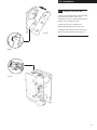
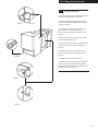
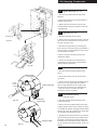
5.6
Assembly of Rear Flue
1. Remove the rear air box blanking plate from
the back plate by releasing the three screws
(Fig. 27).
Fig. 27
2. Remove the blanking cap at the rear of the
turret, by pushing and turning anti-clockwise to
release the bayonet fitting (Fig. 28).
Blanking Cap
Fig. 28
3. Locate the swaged end of the flue duct over
the bayonet fitting on the turret, taking care not to
damage the 'O' ring. Lock the flue duct in place
by pressing in and turning clockwise (Fig. 29).
4. Ensure all seams of the air duct sections are
uppermost and that the 'O' ring seal is in position
against the sealing flange.
5. Fit the air duct over the flue duct and draw
towards the back plate, ensuring that the flue
duct locates into position in the terminal end of
the air duct.
6. Engage the bayonet slots of the air duct over
the location lugs of the back plate opening and
press and turn clockwise to secure the air duct to
the back plate (Fig. 30).
Flue Duct
Fig. 29
7. In order to increase security of the flue, the
bayonet tags may be deformed to secure the flue
in position.
Fig. 30
Air Duct
17
5.0 Installation
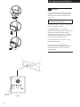
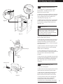
5.7
Fitting the Back Plate
1. Engage the assembly into the hole previously
cut in the wall and slide in place (Fig. 31).
2. Secure the assembly to the wall at the
previously drilled anchorage points with suitable
screws (Fig. 31). Before finally tightening the
screws, check that the assembly is level.
3. Make good between the wall and the air duct
outside the building if the internal fitting kit has
not been used (Fig. 32).
4. The flue trim provided may be fitted if required,
to neaten up the make-up around the terminal.
This plate may also be used as a protection plate
on outside walls of combustible material.
Fig. 31
Fig. 32
Fig. 33
18
5. Fit the trim over the flue terminal and mark
through the four securing holes. Remove the trim,
drill holes 63mm (21/2 in) deep to accept suitable
wall plugs. Fit the trim over the flue terminal and
secure using suitable screws (Fig. 33).
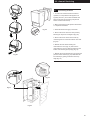
5.0 Installation
5.8
Left or Right Flue
NOTE: If the flue terminal is inaccessible from
outside the building, it is necessary to fix the
internal fitting kit in position before continuing
with the installation. (See section 5.15 Internal
Fitting Kit of these instructions).
1. The procedure for fitting the appliance flued to
the left or right hand side is the same.
2. 30-40-50 PF - Left/Right Hand Side maximum
flue 584mm (23 in).
3. 60-70-80 PF - Left/Right Hand Side maximum
flue 533mm (21 in).
4. Using the previously marked flue hole centre
and the two marks made at the triangular cutouts
of the template, mark the horizontal centre line for
the flue assembly (Fig. 34).
5. Extend this line either left or right as required,
to the corner of the room (Fig. 34).
6. Extend the horizontal centre line around the
corner for approximately 300mm (12 in). Ensure
that the line remains horizontal by checking with a
spirit level (Fig. 35).
Fig. 34
Fig. 37
7. From the wall template remove the detachable
section outlined and marked. Using this as a
template, line up the horizontal triangular cut outs
with the extended 300mm (12 in) line and make
sure that the flat of the template is butted up
against the corner of the wall (Fig. 36).
8. If the appliance mounting wall is out of true, use
string or a straight edge to determine the true
corner position and mark a vertical line to
accommodate the flat edge of the template.
9. Holding the template firmly, mark the vertical
centre line for the flue assembly by marking the
point at the outer corners of the upper and lower
cut outs (Fig. 37).
Fig. 35
Fig. 38
10. Remove the template and draw a vertical line
between the two marks. The intersection of the
vertical and horizontal lines is the centre of the
flue hole (Fig. 38).
11. For installations where the flue terminal is
inaccessible from the outside, an internal fitting kit
is available. This can be obtained free of charge
from your local merchant.
12. If using the internal fitting kit a 117mm (45/8 in)
diameter hole is required.
Fig. 36
Fig. 39
13. Cut a hole approximately 107mm (41/4 in)
diameter in the masonry for the 100mm (4 in)
diameter flue duct (Fig. 39). (Use of a core drill is
recommended. When using a core drill, it is
important to keep the drill level and square,
particularly with the wall onto which the boiler is to
be fitted).
14. Drill the anchorage holes 63mm (21/2 in) deep
to accept suitable wall plugs.
19
5.0 Installation
5.9
R
Side Flue Preparation
1. For both Left and Right Hand Flue - Measure
the distance from the wall to the nearest line
marked from the template. This will be known as
distance R (Fig. 40).
Fig. 40
2. Measure the thickness of the wall from the
inside. This will be known as distance W (Fig 41).
3. Add these two figures together plus 168mm
(65/8 in) for 30-40-50 PF and 224mm (87/8 in) for
60-70-80 PF
W
4. 30-40-50 PF:
Flue Duct Length = R + W + 168mm (65/8 in)
Fig. 41
5. 60-70-80 PF:
Flue Duct Length = R + W + 224mm (87/8 in)
6. Mark off the appropriate length from the
swaged end of the flue duct. Cut the duct to
length and dispose of the unwanted length. (Use
the tape provided to give an accurate cutting
guide by wrapping it around the flue duct with the
edge marking the cutting line) (Fig. 42).
30/40/50 = R + W + 168mm
Fig. 42
60/70/80 = R + W + 224mm
7. Take the telescopic air duct from its pack.
Open the air duct out to the length:(30-40-50 PF) R + W + 91mm (39/16 in)
(60-70-80 PF) R + W + 147mm (53/4 in)
8. Using the tape provided seal the joints of the
three sections of the air duct, ensuring an overlap
of at least 30mm (1 3/16 in) at each joint (Fig. 43).
30/40/50 = R + W + 91mm
60/70/80 = R + W + 147mm
Fig. 43
NOTE: The seams of all three sections must
be in line.
9. If the wall thickness (W) plus the distance from
the wall to the side of the boiler case (R) is less
than 202mm (8 in), it will be necessary to cut the
components of the air duct to make up the
appropriate size. Dispose of the centre section as
this is not required (Fig. 44).
Wall Thickness - 30mm
Fig. 44
Wall Thickness - 30mm
(30-40-50 PF) R + W + 91mm (39/16 in)
(60-70-80 PF) R + W + 147mm (53/4 in)
10. Engage the sections, one inside the other,
then open the assembly out to wall thickness.
Tape the sections together using the tape
provided, ensuring that the seal is good (Fig. 45).
NOTE: The seams of both sections must be in
line.
Fig. 45
20
5.0 Installation
Air Box
Blanking Plate
5.10
Fitting the Flue and Back Plate
1. NOTE: There are two options for fitting the
flue and back plate they are:
Method A - Fitting the flue and back plate as an
assembly (usually used where there are no side
clearance problems).
Fig. 46
Turret
Fig. 47
Method B - Pre-fitting the flue through the wall,
fitting the back plate to its position on the wall
and then connecting the two together (usually
used where side clearances are restrictive).
Blanking
Cap
5.11
Method A
1. Remove the left or right hand air box blanking
plate, as appropriate, from the back plate air box
by releasing the three screws (Fig 46).
2. Rotate the turret to face the selected opening
(Fig. 47) and remove the side blanking cap by
pushing in and turning anti-clockwise to release
the bayonet fitting (Fig. 48).
Fig. 48
3. Locate the swaged end of the flue duct over
the bayonet fitting on the turret, taking care not
to damage the 'O' ring. Lock the flue in place by
pressing in and turning clockwise (Fig. 49).
4. Ensure all seams of the air duct sections are
uppermost and that the 'O' ring seal is in position
against the sealing flange.
Flue Duct
Fig. 49
5. Fit the air duct over the flue duct and draw
towards the air box on the back plate, ensuring
that the flue duct locates into position in the
terminal end of the air duct. Engage the bayonet
slots of the air duct over the location lugs of the
back plate opening and press and turn clockwise
to secure the air duct to the air box (Fig. 50).
6. In order to increase security of the flue, the
bayonet tags may be deformed to secure the
flue in position.
Air Duct
Fig. 50
21
5.0 Installation
5.11
Method A (Cont)
7. Engage the assembly into the hole previously
cut in the wall and slide into place.
8. Secure the assembly to the wall at the
previously drilled anchorage points with suitable
screws. Before finally tightening the screws,
check that the assembly is level (Fig. 51).
9. Make good between the wall and the air duct
inside and outside the building if the internal fitting
kit has not been used (Fig. 52).
Fig. 51
10. The flue trim provided may be fitted, if
required, to neaten up the make-up around the
terminal. This plate may also be used as a
protection plate on outside walls of combustible
material.
11. Fit the trim over the flue terminal and mark
through the four securing holes. Remove the trim,
drill holes 63mm (21/2 in) deep to accept suitable
wall plugs. Fit the trim over the flue terminal and
secure using suitable screws (Fig. 53).
Fig. 52
Fig. 53
22
5.0 Installation
Air Box
Blanking Plate
5.12
Method B
1. Remove the left or right hand air box blanking
plate, as appropriate, from the back plate air box
by releasing the three screws (Fig. 54).
2. Rotate the turret to face the selected opening
(Fig. 55) and remove the side blanking cap by
pushing in and turning anti-clockwise to release
the bayonet fitting (Fig. 55a).
Fig. 54
Blanking
Cap
Turret
Fig. 55
3. Fit the support clamp provided, 60mm (21/2 in)
from the plain end of the flue tube and tighten with
the two screws (Fig. 56).
4. Fit the air duct over the flue duct ensuring that
the flue duct locates into position in the terminal
end of the air duct.
Air Duct
Fig. 55a
60mm (21/2 in)
Fig. 56
Flue Duct
Support Clamps
Fig. 57
5. Ensuring all seams of the air duct are
uppermost, engage the air duct into the hole
previously cut in the wall and through holes in
other partitions (cupboards, walls, etc). Ensure
that the bayonet ends of the air duct and flue are
clear of the previously marked back plate area or
that they overhang it by no more than 50mm (2in).
Ensure that the ‘O’ ring seal is in position against
the sealing flange of the air duct (Fig. 57).
6. Secure the back plate to the wall at the
previously drilled anchorage points with suitable
screws. Before finally tightening the screws,
check that the assembly is level (Fig. 57).
7. Draw the flue duct towards the back plate air
box and locate the swaged end of the flue duct
over the bayonet fitting on the turret, taking care
not to damage the ‘O’ ring. Lock the flue in place
by pressing in and turning clockwise.
8. Draw the air duct towards the air box on the
back plate, ensuring that the flue duct is located
into position in the terminal end of the air duct.
Engage the bayonet slots of the air duct over the
location lugs of the air box opening and press and
turn clockwise to secure the air box to the air
duct.
9. In order to increase security of the flue, the
bayonet tags may be deformed to secure the flue
in position.
10. Make good between the wall and the air duct
inside and outside the building if the internal fitting
kit has not been used (Fig. 58).
Fig. 58
Fig. 59
11. The flue trim provided may be fitted if
required, to neaten up the make-up around the
terminal. This plate may also be used as a
protection plate on outside walls of combustible
material.
Fit the trim over the flue terminal and mark
through the four securing holes. Remove the trim,
drill holes 63mm (21/2 in) deep to accept suitable
wall plugs. Fit the trim over the flue terminal and
secure using suitable screws (Fig. 59).
23
5.0 Installation
5.13
Terminal Guard
1. When codes of practice dictate the use of
terminal guards, they can be obtained from most
plumbers and builders merchants nationwide.
2. When ordering a terminal guard, quote the
appliance model number.
3. The guard manufacturers listed below can be
contacted for terminal sizes and guard model
numbers.
Tower Flue Components Ltd.,
Tower House,
Vale Rise,
Tonbridge,
Kent.
Tel: 01732 351555.
Quinnell, Barrett & Quinnell,
884 Old Kent Road,
London, SE15 1NL.
Tel: 0171 639 1357.
5.14
Fitting a Terminal Guard (Fig. 60)
1. Position the guard over the terminal on the
outside wall. Ensure the guard is equally spaced
about the terminal. Mark the fixing positions.
2. Drill and plug fixing the positions then secure
the guard to wall.
Fig. 60
24
5.0 Installation
5.15
Wall Thickness
Internal Fitting Kit
1. The internal fitting kit (available from
merchants free of charge quoting Baxi Part
No. 226441) is suitable for walls between 100mm
(4in) and 280mm (11in) in thickness.
2. TO INSTALL THE KIT - Mark the flue hole
centre as described in section 5.4 or 5.8. Cut a
hole in the masonry approximately 117mm (45/8
in) diameter for the internal fitting kit. The use of
a core drill is recommended. (When using a core
drill, it is important to keep the drill level and
square).
Fig. 61
3. Measure the wall thickness and from this
dimension subtract 10mm (3/8 in) (Fig. 61).
4. Remove the wall liner from its packing and
remove the end piece (Fig. 62).
Fig. 62
5. Mark off the dimension, wall thickness - 10mm
(3/8 in), measuring from the beaded end of the
duct and cut off the remaining length of the duct.
Ensure that the cut is square and reasonably
straight (Fig. 63).
Wall Thickness - 10
Fig. 63
25
5.0 Installation
5.15
Fig. 64
Internal Fitting Kit (Cont)
6. Refit the end piece to the liner and open out to
the thickness of the wall. Seal the two pieces
together using the tape provided with the kit
(Fig 64).
7. Slide the assembled wall liner into the hole in
the wall until the tags stop against the inner wall
with the seam of the liner uppermost. Mark the
positions of the holes in the tags on the wall and
then rotate liner so that tags reveal marks
(Fig. 65).
8. Drill and plug the wall in these positions
(Fig. 66).
Fig. 65
9. Rotate liner back until the tags align with the
holes drilled and secure it to the wall using
suitable screws (Fig. 67).
10. Make good between the edge of the liner
and the outside wall with cement mortar or a
similar substance, by reaching through the liner
and pressing the mortar between liner and the
outside brick work (Fig. 68). Make good between
the liner and the inside wall. Apply soap solution
to the ‘O’ ring inside the liner.
11. The rest of the installation may now proceed
as described.
Fig. 66
Fig. 67
Fig. 68
26
5.0 Installation
5.16
Fitting the Combustion Box
1. Offer up the combustion box to the back plate
and locate the rear bottom edge of the
combustion box onto the self locating support at
the base of the wall plate (Fig. 69).
2. Swing the top of the combustion box
backwards against the top air box (Fig. 70).
Fig. 70
3. Engage the two retaining latches and secure
with the 'R' clips previously removed (Fig. 71).
Fig. 69
Fig. 71
27
5.0 Installation
5.17
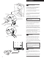
Fan
Electrical Connections
Pressure
Switch
b
br
gy
br
w
bk
bk
w
b
Gas Valve
gy
or
b
r
g/y
or
or
Spark Electrode
w
g
Key
y
Thermostat Sensor
or/bk
y
y/r
y/bk
r/b
L
230V
Pump
N
External
Controls
S/L
L
Schematic
Wiring
Diagram
PCB
Main Gas Valve
r
b
or
Overheat
Thermostat
or
w
28
N
Pilot Gas Valve
b
or
N
Fan
b
N
br
Pressure Switch
w
gy
bk
y
Thermostat Sensor
y
or/bk
or/bk
r/b
y/bk
y/r
Overheat
Thermostat
Control
Potentiometer
& Switch
Spark Electrode
Control
Potentiometer
& Switch
br - brown
b - blue
r - red
w - white
bk - black
or - orange
gy - grey
y - yellow
g - green
g/y - green & yellow
or/bk - orange & black
r/b - red & blue
y/bk - yellow & black
y/r - yellow & red
NOTE: The method of connection to the
electricity supply must facilitate complete
electrical isolation of the appliance.
Connection may be made via a fused double
pole isolator with a contact separation of at
least 3mm (1/8 in) in all poles and serving the
appliance and system controls only. All cables
should be routed to avoid hot surfaces.
WARNING - THIS APPLIANCE MUST BE EARTHED.
4 core input cable for connection to the appliance
must be not less than 0.75mm2 (24 x 0.2mm)
PVC grade to IEC 227 code 53 (heat resisting).
External controls and the appliance MUST be
supplied via the same isolator.
NOTE: Polarity of the appliance MUST be
correct otherwise the appliance will not
operate correctly.
5.0 Installation
5.18
Making the Electrical Connections
1. Remove the cover from the control box by
removing the 2 screws (Fig. 72).
2. Slide the box forward for easier access.
3. The terminal strips may be removed by
carefully pulling them forward. Connect the supply
cable and the pump cable to the terminal strips
(Fig. 74).
IMPORTANT - When installing in conjunction
with a thermal store or heat store please refer
to the store manufacturers installation
instructions when wiring the boiler.
4. The pump must be connected to the boiler
terminals.
5. A permanent live must be connected to the 'L'
terminal.
6. The switched live must be connected to the
'S/L' terminal.
7. Clamp the cables in the grips provided. Ensure
that the lengths of the supply cables are such that
the current carrying wires become taut before the
earth wires if the cable should pull out of the cable
clamp (Fig. 73).
Fig. 72
8. Tuck the cables under the box and clip to the
wall where necessary. Make sure sufficient slack
is left to allow the box to slide forward for future
access.
9. A cable clip is provided in the base of the box.
Fig. 73
Switched Live
Permanent Live
Neutral
Pump Earth
Earth
Pump Neutral
Pump Live
Fig. 74
29
5.0 Installation
5.19
Water Connections
1. The boiler has two side water connections, the
top connection being FLOW and the bottom
connection being RETURN (Fig. 75).
2. It is essential that FLOW and RETURN pipes
are connected to the correct fittings.
3. The top flow connection incorporates the boiler
thermostat, overheat thermostat and a venting
point (Fig. 76).
Venting Point
Flow Pipe
Fig. 75
Plastic
Shroud
in place
Thermostat Clip
4. A copper elbow, compression nut and olive are
provided in the kit for the return connection.
NOTE: Drain cocks should be fitted to all the
system's low points.
5. Connect the two electrical tags of the thermostat
lead to the connections on the thermostat - either
wire can be connected onto either connection there is no polarity (Fig. 76).
Boiler Thermostat
Overheat
Thermostat
Fig. 76
6. Remove the overheat thermostat and clip from
the plastic kit bag. Engage the thermostat in the
clip as shown (Fig 76). Prise the clip over the flow
pipe as near to the vent as possible (Fig. 76 & 77).
7. Connect the two electrical tags from the wiring
harness to the terminals on the overheat
thermostat (Fig.77) - either wire can be connected
onto either terminal - there is no polarity.
Orange Leads
5.20
Pipe Routes
1. Ensure that any pipework is routed so as to
leave the boiler via the spaces at the rear of the
outer case, either at the top or at the bottom.
Fig. 77
2. Pipes may be dropped down within the outer
case in the spaces between the back plate and the
combustion box.
NOTE: It is important that the pipework does
not interfere with the correct fitting of the outer
case and a space of 14mm clearance must be
left between any vertical pipes and the outer
edge of the back plate.
5.21
Gas Connection
1. Connection to the gas supply is RC1/2 (1/2 in
BSPT internal) located at the rear of the gas cock
(Fig. 78).
Fig. 78
30
2. When connecting the gas feed pipe, the control
box may be pulled forward to give greater access.
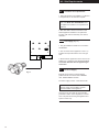
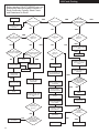
6.0 Commissioning the Appliance
6.1
Commissioning the Appliance
1. Flush the whole system in accordance with BS
5793:1992 (see Section 3.1 Water Circulating
Systems). Check for water leaks.
2. Purge away air from the supply pipe at the gas
service cock. (BS 6891: 1988) (Fig. 79).
3. Ensure that the electrical supply is isolated.
4. Check the electrical supply for earth continuity,
polarity, short circuit and resistance to earth.
Fig. 79
5. Turn the gas service cock anti-clockwise to the
ON position and check for gas soundness up to
the gas valve.
6. Loosen the pressure test point screw on the
right hand side of the gas control valve (there is
no need to completely remove this screw to
obtain a pressure reading) and connect a
pressure gauge.
7. Turn the boiler thermostat control knob fully
anti-clockwise to the OFF position marked 0
(Fig. 80).
8. Ensure that the electricity supply is turned ON
and set any external controls to the ON position.
9. Turn the boiler thermostat knob fully clockwise.
4
5 6
3
2
Burner On
*
Pilot On
Fan On
Boiler On
11. The sparking will continue until the pilot light
is established (Fig. 81) and then the main burner
will light from the pilot flame.
0
1
Overheat
10. The fan will start running and after
approximately 5 seconds, the ignition spark will
commence. (NOTE: This may increase up to 1
minute in extremely cold weather).
12. Check that both the main burner and the pilot
are alight by observing through the viewing
window. The indicator lights should also be
illuminated.
Overheat Neon
Warning
13. Should this sequence not occur, then refer to
the fault finding section of these instructions.
Fig. 80
17
3
NOTE: The pilot rate for this appliance is
factory set, sealed and therefore nonadjustable.
Fig. 81
31
6.0 Commissioning the Appliance
Input
Btu/h
Model
kW
Setting Pressure
mbar
in wg
30
Maximum
Minimum
10.99
7.33
37, 500
25, 000
16.0 + 0.5
8.0 + 0.5
6.4 + 0.2
3.2 + 0.2
40
Maximum
Minimum
14.65
11.36
50, 000
38, 750
16.0 + 0.5
10.0 + 0.5
6.4 + 0.2
4.0 + 0.2
50
Maximum
Minimum
18.32
15.02
62, 500
51, 250
16.0 + 0.5
11.5 + 0.5
6.4 + 0.2
4.4 + 0.2
60
Maximum
Minimum
21.98
18.68
75, 000
63, 750
16.0 + 0.5
11.5 + 0.5
6.4 + 0.2
4.4 + 0.2
70
Maximum
Minimum
25.64
22.35
87, 500
76, 250
16.0 + 0.5 6.4 + 0.2
12.16 + 0.5 4.8 + 0.2
80
Maximum
Minimum
29.31
22.35
100, 000
76, 250
16.0 + 0.5
9.5 + 0.5
6.4 + 0.2
3.8 + 0.2
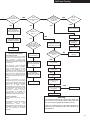
6.1
Commissioning the Appliance (Cont)
1. From the table opposite check that the main
burner pressure is correct after the appliance has
been running for 10 minutes.
2. Check for gas soundness, with main burner
alight, using leak detection fluid.
3. If necessary, adjustment to main burner
pressure can be made by altering the regulator as
shown (Fig. 82).
4. To alter the burner pressure, turn the adjustment
screw in either direction until the required pressure
is obtained.
5. Turn the boiler thermostat to the OFF position
marked 0. Screw home the pressure test point
screw. Turn the boiler thermostat knob to the
required setting.
6. The boiler and system should be run and then
flushed and treated in accordance with
BS 5793:1992 and the flushing agent / inhibitor
manufacturers instructions. When all the air has
been removed from the water circuit, the pump and
radiators should be balanced to achieve the design
temperature drop across the system.
7. Make a final check for gas soundness and set
any timer control, room thermostats etc. to the
customer's specific requirements.
8. The boiler is protected by an integral frost-stat,
but if the boiler is not to be used for a long period
of time, the system should be drained.
Burner Pressure
Test Point
Fig. 82
NOTE: The frost thermostat operates even if
the boiler thermostat is in the OFF position and
it is necessary therefore, if the system is
drained, for the external electrical and gas
supplies to be isolated.
It is recommended that a label be affixed to the
appliance to draw attention to the fact that the
system has been drained.
Regulator
32
WARNING - If the system is filled with very cold
water and the boiler lit, the action of the frost
protection thermostat will prevent the boiler
from shutting down before the water
temperature reaches 10°C.
7.0 Fitting the Outercase
7.1
Fitting the Outercase
1. The warning label may be removed unless the
boiler is to be fitted within a cupboard.
Fig. 83
Infill Panel
2. Taking the ready assembled outercase, the
front door of which has already been removed,
proceed as follows:
3. If the appliance is flued to the left or to the
right, remove the relevant infill panel by
removing the retaining clips and fixing screws
(Fig. 83).
4. Offer the outer case up to the hooks on the
top of the back plate (Fig. 85).
5. Ensure that the outer case is located over the
lower tabs on the back plate on both sides
(Fig. 86).
Fig. 84
6. Using the two screws previously removed,
secure the outer case to the combustion box
(Fig. 84).
7. Replace the lower front door panel.
8. Instruct the user in the operation of the boiler
controls. Hand over both the Users Operating
and Installation Instructions giving advice on the
necessity of regular servicing.
Fig. 85
Fig. 86
33
8.0 Overheat Cut-off Device
1
8.1
Operation
1. The overheat cut-off device is of the manual
reset type and therefore it is important that the
user knows how to reset the control should it
ever cut out.
NOTE: Cut-out is indicated by illumination of
the neon light on the control box.
2
2. Remove the lower door panel by following the
sequence of diagrams (Fig 87).
3. To reset the boiler - Turn the boiler
thermostat control knob fully anti-clockwise to the
OFF position marked ‘0’ (Fig. 88). Wait ten
seconds, turn the control knob clockwise to the
required thermostat setting, the red neon goes
out, the boiler will start automatically.
3
4. No adjustment to the gas controls or main
thermostat are required.
5. If the overheat thermostat drops out
repeatedly, refer to the fault finding chart at the
rear of this booklet or consult a competent
service engineer.
Fig. 87
4
5 6
3
2
0
34
Pilot On
Fan On
Boiler On
Overheat
Overheat Neon
Warning
Fig. 88
Burner On
*
1
9.0 Annual Servicing
1
9.1
Dismantling the Boiler
1. To ensure its continued safe and efficient
operation, it is important that the appliance is
regularly serviced. ( For location of British Gas
service test point see Changing Components
section of these instructions).
2
2. Before servicing the boiler please read Section
1.3 Important Information.
Fig. 90
3. Isolate the electrical supply to the boiler.
4. Remove the outer case lower door panel by
following the sequence of diagrams (Fig. 89).
5. Remove the outer case from the boiler by
unscrewing the two screws and lift the case clear
(Fig. 90).
3
6. Release the four latches holding the
combustion box door (Fig. 91). Remove the
combustion box door by pulling forward from the
bottom and unhooking its top edge (Fig. 93).
7. Release the 5-pin electrical plug connecting the
pressure switch and fan (Fig. 92). Withdraw the
fan assembly by pulling forwards from the top
edge (Fig. 93).
Fig. 89
Fig. 92
Fig. 91
Fig. 93
35
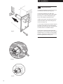
9.0 Annual Servicing
Baffles - 30, 40, 50, 60, 70 models
9.2
Cleaning the Combustion Box
1. Remove the burner assembly by pulling it
forward (Fig. 94).
2. Lightly brush any dirt from the top of the burner
blades and ensure that the ports are free from
obstruction.
3. Lift the baffles out of the heat exchanger, using
the corner tabs on 30,40,50,60,70 models
(Fig. 94).
9.3
Cleaning the Heat Exchanger
1. The heat exchanger may be cleaned by
insertion of a thin metal strip e.g. a hack saw
blade or steel rule, from above or below, taking
care not to damage any insulation.
Fig. 94
2. Clean the front and rear fin sections and
ensure that any blockages are cleared.
9.4
Cleaning the Burner Injector
1. Remove the injector which is screwed into the
burner feed manifold (Fig. 95).
2. Examine and clean carefully, then replace
ensuring that the copper washer is in position.
Tighten the injector fully.
Electrode
Fig. 96
60, 70 & 80 PF
Models Only
Fig. 95
9.5
Cleaning the Pilot
1. Disconnect the spark electrode lead at the
electrode (Fig. 96).
2. Unscrew the electrode from the manifold and
withdraw the electrode (Fig. 96).
3. Remove the right hand side insulation carrier
bracket by releasing the screw. Remove the side
insulation (Fig. 94).
Pilot Hood
Pilot Injector
4. Release the screw securing the pilot hood and
remove (Fig. 96a).
Sealing Washer
5. Carefully remove the pilot injector (Fig. 96a).
Examine and clean it as necessary. Do not use a
wire or pin to clean the injector orifice.
Fig.96a
Baffles 80 models only
Baffle 30, 40, 50, 60, 70 models
6. Examine the sealing washer (Fig. 96a) and
replace if it is damaged in any way. Reassemble
in reverse order.
7. Replace all components in reverse order, (On
30,40,50,60,70 models refit the rear baffle by
holding it at an angle and locating the lower
fingers between the heat exchanger and rear
insulation. Lower it into position as shown)
(Fig. 97).
8. Check that the seal to the combustion box door
is good.
36
Fig. 97
9. Re-commission the boiler before use, checking
for gas soundness and ensuring all controls are
working correctly.
10.0 Changing Components
1
10.1
Changing Components
1. When changing components ensure that the
gas and electrical supplies are isolated before the
work is started.
2. Before changing any components please read
Section 1.3 Important Information.
2
Fig. 99
3. Remove the outer case lower door panel
(Fig. 98).
4. Remove the outer case from the boiler by
unscrewing the two screws and lift the case clear
(Fig 99).
3
10.2
Replacing the Circuit Board
1. Ensure that the electrical supply is isolated.
2. Remove the cover from the front of the controls
box (Fig. 100).
3. Release the mains cables from the cable
clamps and unplug the mains connection blocks
from the circuit board (Fig. 101).
Fig. 98
4. Remove the screw retaining the thermostat
control panel and slide the circuit board from the
box.
5. Carefully withdraw the centre pin from the
retaining rivet which then allows the retaining rivet
to be removed. Remove the thermostat control
panel (Fig. 102). (On reassembling ensure the
control panel is located over the retaining rivet
body before inserting the centre pin.)
6. Disconnect the plugs from the sockets on the
circuit board (Fig. 103).
7. Replace new circuit board in reverse order
checking that the connections are correct as
shown in the diagram (See Electrical Connections
section 5.17 of these instructions) and that the
harness is retained in the strain reliefs.
Fig. 100
Fig. 101
Fig. 102
Retaining
Rivet
Centre
Pin
Fig. 103
37
10.0 Changing Components
10.3
Ignition Electrode (Fig. 104)
1. Disconnect the spark electrode lead at the
electrode.
2. Unscrew the electrode from the manifold and
withdraw the electrode.
3. Replace the new electrode in reverse order,
ensuring that the sleeving is pushed over the end
of the electrode.
10.4
Gas Valve (Fig. 105)
1. Disconnect the inlet gas cock union.
Electrode
2. Remove the cover from the front face of the gas
valve and remove the electrical connections from
the tags on the gas valve.
Fig. 104
3. Disconnect the gas valve by unscrewing the
three screws on the top face of the gas manifold. If
access to these screws is dificult the valve can be
removed with the manifold.
4. Remove the gas valve being careful not to
damage the gasket.
5. Fit the new gas valve by re-assembling all
components in reverse order, ensuring that the
gasket is properly positioned.
Fig. 105
10.5
Thermostat Sensor (Fig. 106)
1. Disconnect the two electrical tags from the
sensor.
Flow Pipe
Plastic
Shroud
in place
2. Unscrew the sensor from the top flow water
connection.
Thermostat Clip
3. Screw in the new sensor with the plastic shroud
in place as a cover guard. Make sure that the
sensor is fully tightened into the top flow water
connection and connect the two electrical tags
- either wire can be connected onto either
connection - there is no polarity.
10.6
Overheat
Thermostat
Fig. 106
Over-Heat Thermostat
(Figs.106 & 107)
1. Disconnect the two electrical tags from the
overheat thermostat.
2. Remove the clip and thermostat from the pipe,
noting its position. Remove the retaining ‘O’ ring if
one is fitted and discard, disengage the thermostat
from the clip. If the clip is a metal one, discard and
use the plastic clip supplied in the kit.
Orange Leads
38
Fig. 107
3. Engage the new thermostat in the clip. Prise the
clip over the flow pipe ensuring it is positioned as
previously. Connect the two electrical tags to the
terminals on the overheat thermostat - either wire
can be connected onto either terminal - there is no
polarity.
10.0 Changing Components
10.7
Changing Components (Cont)
1. To change Fan - Pressure Switch - Burner Burner Injector - Pilot Burner Injector - Gas
Manifold, proceed as follows:-
Fig. 109
2. Release the four latches holding the combustion
box door (Fig. 108). Remove the combustion box
door by pulling forward from the bottom and
unhooking its top edge (Fig. 110).
3. Release the 5-pin electrical plug connecting the
pressure switch and fan (Fig. 109). Withdraw the
fan assembly by pulling forwards from the top
edge (Fig. 110).
Fig. 108
10.8
Fan (Fig. 111)
IMPORTANT - 80 PF Models Only. On
appliances up to serial no 8999 use replacement
fan Baxi Part No 229422 G.C.No 364 979.
From serial no 9000 use replacement fan Baxi
Part No 237578 G.C.No 170 615.
Fig. 110
1. Disconnect sensing probe from the pressure
switch at rubber tube connector.
2. Disconnect the 2 fan wires from the connection
on the electrical plug. Unscrew bracket securing
sensing probe into top of fan and remove the
sensing probe. Remove the 3 screws securing the
fan to the fan hood.
Fan
Outlet Flange
3. Remove the two screws securing the fan outlet
flange to the fan and remove. Clean all sealing
mastic from the outlet flange.
4. Fit the outlet flange onto the new fan, fix with
the 2 screws and seal the outside gap between the
fan body and the outlet fan with the mastic
provided.
Sensing Tube
5. Fit the new fan and re-assemble all components
in reverse order of dismantling, reconnect the new
fan wires into the connections on the electrical
plug - either wire can be connected into either
connection.
Fig. 111
Sensing Tube
10.9
Pressure Switch (Fig. 112)
Grey
1. Disconnect sensing tube.
Black
2. Remove the screw securing the pressure switch
to its bracket and unhook the pressure switch.
White
3. Disconnect the 3 electrical terminals from the
pressure switch. Note the position of the tags
before removal and reconnect in correct order.
Fig. 112
4. Fit new pressure switch and re-assemble all
components in reverse order of dismantling
ensuring that the electrical terminals are
connected to their correspondingly marked tags.
39
10.0 Changing Components
10.10 Burner (Fig. 113)
1. Remove the burner assembly by pulling it
forward.
2. Fit new burner and re-assemble all components
in reverse order of dismantling.
10.11 Burner Injector (Fig. 114)
Fig. 113
1. Release and remove the burner injector which
is screwed into the burner feed manifold.
2. Fit the new burner injector ensuring that the
copper washer is in position. Tighten the injector
fully.
3. Re-assemble all components in reverse order.
10.12 Pilot Burner Injector (Fig. 115)
1. Remove the right hand side insulation carrier
bracket by releasing the screw. Remove the side
insulation panel.
60, 70 & 80 PF
Models Only
2. Release the screw securing the pilot hood and
remove. Carefully remove the pilot injector. Fit the
new pilot injector ensuring the new sealing washer
is in position. Tighten the injector fully.
Fig. 114
Pilot Hood
Pilot Injector
3. Re-assemble all components in reverse order.
Sealing Washer
10.13 Gas Manifold (Fig. 116)
Fig. 115
1. Remove the right hand side insulation carrier
bracket by releasing the screw. Remove the side
insulation panel (Fig. 113).
2. Remove the two screws securing the manifold
from the inside of the combustion box and slide
the manifold forward from under the two rear
locating studs.
3. Remove valve and ancillary components from
manifolds as necessary.
Fig. 116
40
4. Replace all ancillary components onto manifold
and replace manifold by sliding rear edge
backwards under the two rear locating studs and
securing from inside the combustion box using the
two screws previously removed. Ensure that the
sealing gasket is properly positioned and
undamaged.
1.0 Introduction
11.0
Short parts list
44
11.1
39
Short Parts List
Key
No
Description
Model
G.C.
No
Manuf'rs
Part No
39
Burner
30-40-50
364 878
231708
60-70-80
364 879
231709
30
364 880
231354
40
364 881
231355
50
364 882
228104
60
364 873
231776
70
E01 623
239619
44
Burner Injector
40
75
71
30
364 981
231777
Ignition Pilot Kit
All models
170 558
236142
75
Electrode Lead
All models
364 745
225826
71
Control Knob
All models
364 886
230981
30
Viewing Window Kit
All models
364 588
224183
53
Pressure Switch
All models
379 033
230068
25
Insulation R.H.
All models
364 889
230653
24
Insulation L.H.
All models
364 890
230652
26
Retaining Brackets
All models
364 891
230817
61
Control Valve
All models
379 202
231857
77
Overheat Thermostat
All models
E03 921
241792
66a
Fuse
All models
364 892
231402
48
Fan
30-40-50-60
229421
80 up to serial no 8999
24
26
80
40
25
53
364 979
229422
after serial no 9000
26
170 615
237578
70 from serial no 00001
170 615
237578
Thermostat Sensor
All models
379 030
230204
66
Control Board
All models
379 031
231711
2
Panel Top
30-40-50
364 893
230442
60-70-80
364 894
230863
30-40-50
364 895
230443
60-70-80
170 602
229428
30-40-50
364 897
231406
60-70-80
364 898
231429
30-40-50
364 899
230446
60-70-80
364 900
230868
73
77
3
Panel Upper
61
66a
4
5
Panel Lower
Panel Bottom
73
48
6
Panel L.H.
All models
364 901
230439
7
Panel R.H.
All models
364 902
230951
71a
Potentiometer & Leads
All models
379 960
237140
66
2
6
71a
3
7
4
5
41
12.0 Fault Finding
Before starting FAULT FINDING carry out
preliminary electrical system checks i.e.
Earth Continuity, Polarity, Short Circuit
and Resistance to Earth.
START
Does pump run ?
Is
there a clear
constant spark at
the electrode ?
YES
YES
Does fan run ?
Ensure external
controls are calling
for heat
NO
Is
there mains voltage
at P/L input ?
YES
NO
Is
"Boiler On"
light on ?
NO
YES
Is
there mains voltage
at Pump L output ?
NO
Is
lockout light
on ?
YES
Is
there mains voltage
at S/L input ?
NO
Is
"Pilot On"
light on ?
YES
NO
Check & clean
electrode. Check gap &
lead
YES
Is
"Fan On"
light on ?
Change PCB
NO
NO
Check external
wiring
Check fuse on
circuit board
YES
YES
Change
potentiometer
NO
Note: Under cold
conditions fan run up
time may exceed
1 min
Check control knob
is turned on
Check pressure switch
pipes for leaking or
blockage
Change PCB
Check that the wires
are connected to the
thermostat sensor
No continuity
across fuse,
change fuse
YES
Note: This can occur if
the boiler has
overheated
Check pump wiring
YES
Is there
continuity between
C & NC terminals
on the pressure
switch ?
Check that the fan &
pressure switch plug is
connected
YES
YES
Check continuity
across sensor
(1 M OHM at 20oC)
Investigate
pump
Reset by turning
control knob OFF, wait
10 seconds then turn
ON
Replace pressure
switch
No continuity - change
sensor
Replace fan
Check continuity
across pilot solenoid
(1.5 K OHM)
Does
lockout light
go out ?
NO
Replace
thermostat
NO
No continuity - change
pilot solenoid
Is
there mains at
the fan
connection ?
Check Potentiometer
(see table)
NO
Is there
continuity across
the overheat
thermostat ?
Replace harness
42
NO
YES
Replace fan
YES
12.0 Fault Finding
Does
the pilot burner
light ?
YES
NO
Does
the boiler shut
down when the water
flow reaches
80-84oC ?
Does
the main burner
light ?
YES
YES
NO
NO
Does
pump run
on ?
Boiler satisfactory
Check there is
20mbar gas pressure
at the inlet to gas valve
Is
"Burner On"
light on ?
Replace sensor
YES
Check the pilot injector is
not blocked, partially
blocked or damaged
NO
Are live &
neutral reversed ?
Indicator light inside
box will be lit
Check
Potentiometer
(see table)
Check there is
20mbar gas pressure
at the inlet to gas valve
Replace PCB
Replace the gas
valve
Testing Potentiometer
Three Pin Connector
Set multimeter to the 2 M OHM
scale. Turn potentiometer to the
OFF position, connect the
multimeter leads to the blue/red wire
and centre black/yellow wire of three
pin connector.
The reading on the multimeter
should indicate approx 1 M OHM,
switch potentiometer to the ON
position, the reading on the
multimeter should be approx 1 M
OHM. Slowly turn potentiometer
knob to the FULL ON position, the
reading on the multimeter should
decrease, proportionally down to 0
OHMs.
Connect multimeter to centre
black/yellow wire and red/yellow
wire, turn potentiometer knob to fully
OFF position, reading on multimeter
should be 0 OHM. Switch
potentiometer to ON position, slowly
turn potentiometer knob to the fully
ON position, the reading on
multimeter
should
increase
proportionally to 1 M OHM, turn
potentiometer off. Reading on
multimeter should indicate 0 OHM.
Two Pin Connector
Check potentiometer is in OFF
position.
Set multimeter to continuity, connect
multimeter
leads
to
both
potentiometer
leads.
Turn
potentiometer to the on position, the
multimeter's audible alarm should
now be sounding to indicate
continuity.
Check pilot flame
for correct size
Is
there the
correct burner
pressure at the test
point ?
NO
Set pressure
regulator
YES
Check & clean
electrode. Check spark
gap. Check electrode
lead
Check main injector
is not blocked
YES
Check pilot injector is
not blocked
Check there is
20mbar gas pressure
at the inlet to gas valve
YES
Check pilot flame
size
YES
Replace PCB
Check pilot hood
position and pilot
air flow
YES
Check continuity
across mains solenoid
(5 K OHM)
YES
Change PCB
NO
Change gas valve
Warning
It is important that both the air and flue ducts are
cut to their correct lengths also ensure that the
flue duct is fully engaged in the flue terminal.
Failure to comply with the recommended fitting
instructions will adversly affect the operation of
the appliance.
43
Comp No 230988 - Issue 22 - 11/98
The Baxi Helplines
For General Enquiries
+44 (0)1772
695555
For After Sales Service
+44 (0)1772
695505
For Technical Enquiries
+44 (0)1772
695504
Baxi Heating Limited
Brownedge Road
Bamber Bridge Preston
Lancashire
PR5 6SN
www.baxiheating.co.uk