1
PCR 6
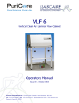
Vertical Laminar Airflow Cabinet
with U.V. Sterilisation
Operators Manual
Issue 05 – September 2013
Puricore International Ltd 175 Kenn Road Clevedon North Somerset BS21 6LH
Tel +44 1275 793000 | Fax +44 1275 341313 | [email protected] | www.puricore.com
Registered in England No: 2695450
CE Marking certifies that this equipment conforms to the following
EEC directives: Low Voltage Equipment – 72/23/EEC & 93/68 EEC
Electromagnetic Compatibility – 89/336/EEC
Certificate No: 0954499
CONTENTS
DESCRIPTION OF PCR WORKSTATION
WORKSTATION ................................................................
.................................................................
................................. 3
FEATURES ................................................................
................................................................................................
.....................................................................................
..................................................... 3
HEPA FILTER ................................................................
................................................................................................
.................................................................................
................................................. 3
INSTALLATION AND OPERATION
OPERATION ................................................................
.........................................................................
......................................... 4
CONTROLS ................................................................
................................................................................................
....................................................................................
.................................................... 4
OPERATION ................................................................
................................................................................................
...................................................................................
................................................... 4
U.V. LIGHTING................................................................
................................................................................................
.....................................................................
..................................... 5
UV Lamp Use Alarm................................................................
................................................................................................
........................................................................
........................................ 5
FILTERS ................................................................
................................................................................................
..............................................................................
.............................................. 6
PrePre-filter ................................................................
................................................................................................
........................................................................................
........................................................ 6
To change prepre-filters ................................................................
................................................................................................
......................................................................
...................................... 6
Main Filter ................................................................
................................................................................................
......................................................................................
...................................................... 6
AIRFLOW ................................................................
................................................................................................
............................................................................
............................................ 7
Low Airflow Alarm ................................................................
................................................................................................
..........................................................................
.......................................... 7
Airflow Monitoring ................................................................
................................................................................................
.........................................................................
......................................... 7
SERVICING................................
SERVICING................................................................
................................................................................................
..........................................................................
.......................................... 8
MAINTENANCE ................................................................
................................................................................................
....................................................................
.................................... 9
PCR 6
Operators Manual
DESCRIPTION OF PCR WORKSTATION
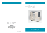
The PCR Cabinet is designed for the production of
PCR and other sterile samples without
contamination. The work area has a HEPA filtered
air down flow to provide minimum of CLASS 100
Air at a laminar velocity of approx. 0.4 m/sec. The
cabinet is fitted with a timer controlled U.V. light for
sterilising the cabinet work-surface and equipment.
A safety door is supplied to cover the work area
whilst cabinet is being sterilised.
The work surface is manufactured from 316 grade
stainless steel for ease of cleaning. SPILLAGES
SHOULD BE REMOVED IMMEDIATELY TO
PREVENT STAINING.
FEATURES
Class 100 Clean Air
Filter Seals Under Negative Pressure
UV Sterilisation Of Cabinet, Instruments And Flasks
Eliminates Contamination
Quiet Operation At 53d(B) A
Stainless Steel Workstation For Easier Cleaning
Compact Design
Unhindered Access To Work Area
Cost Effective
Two Speed Fan To Extend Filter Life
Detachable Front Panel For Operator UV Protection
HEPA FILTER
The HEPA filter is 99.997% efficient against 0.3-micron particles and protected by a
pre-filter. The pre-filter is accessed through the top of the cabinet.
Filter seals are maintained under a negative pressure to prevent potential leakage of
unfiltered air into the work area.
3
PCR 6
Operators Manual
INSTALLATION AND OPERATION
The unit will be supplied ready assembled and with the correctly fused mains 3 pin plug
fitted. The unit can only be connected to the mains supply as follows:
Brown –
Blue Green/Yellow -
Live 220 / 240V
Neutral
Earth
The light and U.V. light plugs into the rear of the head unit.
IMPORTANT THIS APPLIANCE MUST BE EARTHED
CONTROLS
(a)
MAINS ON/OFF ILLUMINATED PUSH BUTTON SWITCH.
(b)
U.V. Lamp and timer control. THE CLOSING PANEL MUST BE IN PLACE
BEFORE OPERATING U.V. LIGHT.
(c)
Fluorescent light switch
OPERATION
1.
Switch cabinet on and allow several minutes for airflow to stabilize and purge the
cabinet. The airflow LED will flash red at switch and change to green when
airflow is correct for use.
2.
Sterilise tray and internal surfaces with a CONTACT sterilant.
3.
Close front of cabinet with panel supplied onto latches.
4.
Press U.V. light switch to illuminate the UV light and operate the timer. The fan
and the fluorescent light will go out and the U.V. light will illuminate.
The UV operating time is user selectable.
Press the UV switch once and the time selected is 5 minutes, the UV LED will
flash once.
4
PCR 6
Operators Manual
For 10 minutes, press the UV button twice, UV LED will flash twice.
For 15 minutes, press the UV button 3 times, UV LED will flash 3 times.
This process can be used to select upto 30 minutes, 6 button presses, UV LED
will flash 6 times.
After the preset time the U.V. light will go off and the UV LED will flash slowly
and the alarm will beep every 4 secs to inform the user the UV cycle has
finished.
5.
Remove the closing panel, store on top of the cabinet. The fan and fluorescent
light will come back on and the cabinet is now ready for use.
NOTE: If the fluorescent light and fan do not come back on automatically, press
the UV button and hold for 2 seconds, or use the ON/OFF button to reset the
cabinet.
U.V. LIGHTING
The U.V. light is germicidal with a wavelength of 254 Nm. The tube is 15 watts.
U.V. light will cause burns to skin and damage eyes in a very short period of time. The
U.V. light must only be used when the closing panel is in place.
The lamps will deteriorate with use. LAMPS SHOULD BE REPLACED AT 1000 hrs
APPROX.
NOTE: The lamp will still emit blue light even when efficiency is greatly reduced.
UV LAMP USE ALARM
There is an alarm to alert the user to the deterioration of the UV lamp, when the UV
cycle is in progress and 1000 hours has been exceeded there will be an audible beep
every minute of the UV cycle.
CAUTION
DO NOT EXPOSE SKIN OR EYES TO U.V. RADIATION FROM THIS LAMP
5
PCR 6
Operators Manual
FILTERS
PRE-FILTER
The pre-filter is mounted on the top of the cabinet and will require occasional
replacement. The filter grade is EU7.
TO CHANGE PRE-FILTERS
a)
Remove both thumbscrews on the head of the cabinet.
b)
Slide top panel backwards approx 30mm to disengage rear overlap and
remove top panel.
c)
Replace pre-filter. NOTE: The filter is graded and should be installed with
coloured surface uppermost.
d)
Replace top panel on head unit 30mm approx to the rear. Slide panel
forwards with top panel under the rear overlap.
e)
Replace thumbscrews.
MAIN FILTER
The main filter is mounted from the top of the cabinet and the seals are under negative
pressure to avoid leakage into the cabinet. The filter is 99.997% efficient against 0.3
micron particles.
To replace the main filter, unlock the side latches and lift off the head unit.
It is helpful to coat the Hepa filter seals with silicone grease.
NOTE. The airflow direction arrow should be pointing downwards.
6
PCR 6
Operators Manual
AIRFLOW
The airflow is monitored by the on board pcb. At switch on the red LED will display
for a short time until the fan has run up and the correct airflow is established. The
green LED will then be illuminated.
Note: The cabinet should only be used when the green LED is illuminated.
A pre-filter is fitted before the main HEPA filter to remove particulates from the airflow.
This EU7 filter provides a very efficient particulate filtration of larger particles.
LOW AIRFLOW ALARM
After a period of time, the pre-filter and or HEPA filter will start to block and reduce the
airflow, the fan will increase the pressure available and as the filters comes to the end
of its life, the red low airflow alarm LED will start to flicker, and then flash repeatedly.
An audible alarm will also sound every 15 minutes.
At this point the pre-filter must be changed, instructions are in the Filter section
If changing the pre filter does not restore the airflow then the HEPA filter also requires
changing, instructions are in the Filter section
AIRFLOW MONITORING
The airflow should be checked at 6 monthly intervals, at a distance of about 100mm
from the filter face. The average airflow should be between 0,35 and 0,5 m/sec.
7
PCR 6
Operators Manual
SERVICING
An annual service is recommended and will cover the following points:
a)
Replace pre-filter and check airflow.
b)
HEPA filter condition check by D.O.P.
c)
Inspection of electrical components, lighting, cables etc.
d)
Cleaning and checking the condition of the glazing and closing panel.
8
PCR 6
Operators Manual
MAINTENANCE
a) Filters. 6 month and 12 month check. See section on Filters.
b) Airflow. Average airflow should be between 0,35 & 0,5 m/sec.
c) Fan. The fan is centrifugal and fitted with thermal cut out. The fan requires
no routine maintenance.
d) Lighting. The fluorescent light and UV tubes are accessible from under the
cabinet. To remove tubes pull back the spring loaded end caps. The
starters are accessed by removing the tube and undoing the cover panel
under the tube.
THE MAINS PLUG MUST BE DISCONNECTED WHEN
REMOVING TUBES AND STARTERS.
Replace U.V. fluorescent tube at least every 1000 hours.
9
PCR 6
Operators Manual
PCR 6
Operators Manual
Puricore International Ltd
175 Kenn Road, Clevedon, North Somerset, BS21 6LH England
UK Tel:
INT Tel:
(01275) 793000
+44 1275 793000
E-mail:
[email protected]
UK Fax:
INT Fax:
(01275) 341313
+44 1275 341313
Website: http://www.puricore.com
PCR 6
Operators Manual
September 2013
Issue 05