1
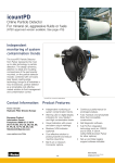
SureFire SLR Operators Manual (230/480 Three Phase models, for SLR systems) For oil or fluid grease • Document Number: 35140-E • Revision: 05-2006 B262E r2 (05-06) Index Safety General. . . . . . . . . . . . . . . . . . . . . . . . . . . . . . . . . . . . . . . . . . . . . . . . . . . . . . . . . . . . . 2 This Operators Manual covers fundamental concepts, which are to be observed for installation, operation and maintenance. Therefore, it is absolutely necessary that the Operators Manual be studied by the person doing the installation prior to installation and start-up. It is also necessary to have this Operators Manual nearby and available for reference in the future. The safety instructions mentioned in this Operators Manual, as well as all national operating and safety regulations for the safe operation of such equipment are to be observed. Application . . . . . . . . . . . . . . . . . . . . . . . . . . . . . . . . . . . . . . . . . . . . . . . . . . . . . . . . . 2 Safety . . . . . . . . . . . . . . . . . . . . . . . . . . . . . . . . . . . . . . . . . . . . . . . . . . . . . . . . . . . . . . 2 Precautions and symbols. . . . . . . . . . . . . . . . . . . . . . . . . . . . . . . . . . . . . . . . . . . 2 Design and Construction. . . . . . . . . . . . . . . . . . . . . . . . . . . . . . . . . . . . . . . . . . . 2 Principle of Operation. . . . . . . . . . . . . . . . . . . . . . . . . . . . . . . . . . . . . . . . . . . . . . 3 Technical Specifications. . . . . . . . . . . . . . . . . . . . . . . . . . . . . . . . . . . . . . . . . . . . 3 Precautions and symbols Overall Dimensions. . . . . . . . . . . . . . . . . . . . . . . . . . . . . . . . . . . . . . . . . . . . . . . 4-5 General precautions and symbols used within this manual are as follows: Wiring and Hydraulic Diagram. . . . . . . . . . . . . . . . . . . . . . . . . . . . . . . . . . . . . . 6 General safety instructions Installation and Commissioning . . . . . . . . . . . . . . . . . . . . . . . . . . . . . . . . . . . . 7 Maintenance and Service. . . . . . . . . . . . . . . . . . . . . . . . . . . . . . . . . . . . . . . . . . . 8 3PAN Electrical safety instructions Troubleshooting . . . . . . . . . . . . . . . . . . . . . . . . . . . . . . . . . . . . . . . . . . . . . . . . . . . . 8 Safety instructions which shall be considered for reasons of safe operation of the lubricator Spare Parts List . . . . . . . . . . . . . . . . . . . . . . . . . . . . . . . . . . . . . . . . . . . . . . . . . . . . 9 How To Order. . . . . . . . . . . . . . . . . . . . . . . . . . . . . . . . . . . . . . . . . . . . . . . . . . . . . . . 9 ATENC Electrical connections made to Earth ground are identified by this symbol General Electrical connections made to the Neutral conductor are identified with a capital “N” Before installing this lubricator, please read this manual carefully. Failure to follow these instructions can result in damage to the product and/or serious bodily injury. The SureFire SLR lubricator meets all of the operating parameters for Bijur Single Line Resistance (SLR) centralized lubricating systems. Conditions and actions that pose potential hazards to the user are marked by this sign N 3PAN AVIS All safety and/or warning labels affixed to the SureFire SLR lubricator must be maintained in a completely legible condition. Also, any modifications made to the SureFire SLR lubricator (or to any of its components) must be approved by Bijur Lubricating Corp. prior to its use, otherwise the warrantee and any liability by Bijur Lubricating Corp. will be null and void. ©Copyright Bijur Lubricating Corporation 2004-2006. Bijur Lubricating Corp. reserves the right to update or improve the technical specifications for this product without prior notice. Design and Construction Company Headquarters and Sales/Service: Bijur Lubricating Corp. 808 Aviation Parkway, Suite 1400 Morrisville, North Carolina 27560-6600 USA Phone: (800) 631-0168 Fax: (919) 465-0516 The basic design of the SureFire SLR lubricator is that of a motor driven gear pump, which sits in a reservoir of lubricant. The motor, gear pump and connecting driveshaft are assembled as a self-contained unit and are “dropped into” the reservoir through a hole in the main structural component, the Top Plate. Installing the motor and pump assembly into the reservoir from the top provides easy access to all of the motor and pump components, including the screen (if applicable) without having to dis-assemble the reservoir. If detaching the reservoir from the Top Plate is necessary, it can be done easily and without any tools on all models other than the 12 liter models, by loosening the external latches that are located on either side of the lubricator. On all models other than the 12 liter models, the Top Plate is mounted to the customer equipment by means of two bolts, and also provides the mounting locations for all of the other lubricator components. The 12 liter models are supported from the bottom. Application The motor, pump and driveshaft assembly delivers pressurized lubricant directly into a channel in the downspout. This channel is sealed by means of O-Rings, and gives the downspout two integral outlet ports, one located at each end. Therefore, the customer may connect the main line plumbing distribution network to either side of the downspout, or to both sides, whichever is more convenient or aesthetically pleasing. B262E r2 (05-06) This SureFire SLR lubricator is ideally suited for use in single-line centralized lubrication systems. In these systems, lubricant is being delivered in pulses and under pressure (pressure and relief cycles) through the main feed lines to resistance fittings (metering units and control units) located near the lube points of the machinery being lubricated. Every use beyond this type of application is not in accordance with the manufacturers’ intended purpose, and the manufacturer is not to be held responsible for any damages resulting from it. The corresponding risk is taken by the user only. Principle of Operation Technical Specifications The SureFire SLR lubricator has a three-phase motor-driven pump that pulls lubricant in from the reservoir and delivers pressurized lubricant to the distribution network through the outlet(s) in the top block under the motor. Pressurizing the distribution network forces all of the resistance fittings in the system to discharge the lubricant to the friction points. Output Volume: 500cc/min @ 60 Hz (415cc/min @ 50 Hz) 200cc/min @ 60 Hz (167cc/min @ 50 Hz) Output Pressure (MAX.): 75 psi (5 bar). This is the pressure relief valve setting. Lubricant Viscosity: Oil, 20-1500 cp, Fluid greases, NLGI 000-00, 1500-40,000 cp As the resistance fittings discharge, the pressure in the network continues to rise until the limit in the pressure switch is reached (pressure switch sold separately). Once this limit is reached, the pressure switch can be used to stop the motor, and momentary pressure in the distribution network becomes greater than the pressure at the outlet side of the gear pump. This pressure differential actuates a quick dump valve which relieves the distribution line pressure back into the reservoir Reservoir Fill Screen: 40 mesh, removable Reservoir Volume: 1.8 Liters, 2.7 Liters, 6.0 Liters, 12.0 Liters Reservoir Material: Clear ABS plastic (12.0 Liter reservoir is steel) Output Connection to Distribution: G1/4 BSPP (minimum 6MM OD main distribution line tubing recommended) Motor Voltage Options: 230/415 50 Hz, 260/480 60 Hz Motor Overload Protection needs to be provided by the host machine and/or its control system. Motor Duty Cycle: S1 (Continuous Duty). Operating Temperature Range:+5°C through +40°C (+40°F through +105°F) IP Rating: IP-54 Sound Pressure: 70 dBA Dry Weights SF2LxDx: 11.0 lbs/4.99 Kg SF3LxDx: 14.0 lbs/6.35 Kg SF6LxDx: 17.5 lbs/7.94 Kg SF12LxDx: 22.25 lbs/10.1 Kg Current Draw and Power Consumption Rated Voltage (+/- 10%) 230/480VAC (50/60 Hz, 3 Phase) Peak Starting Current (amps) 0.8/0.5 Normal Running Current (amps) 0.5/0.4 Max. Current locked rotor (amps) 1.84/1.6 NOTE: 1) Peak and Starting Currents were measured with 40,000cp fluid at 450 psi. 3PANISH &RENCH output pressure. 2) Discharge flows were measured with 0 psi output pressure. AVISOSLR lubricator must NOTIFICATION The SureFire not be used in explosive atmospheres and must not be used for pumping flammable liquids. 'ERM WARNUN B262E r2 (05-06) Overall Dimensions SureFire SLR 1.8L, 2.7L & 6.0L (three phase model) &OHMJTI &TQB×PM (all dimensions are in millimeters) (todas las dimensiones estan en milímetros) %FVUTDI 'SBOÎBJT (alle Abmessungen in Millimeter) (toutes les dimensions sont en millimètres) A B E G F D English Español Deutsch Français H C J Left view Vista lado Izquierdo Ansicht linke Seite Vue du côté gauche Front view Vista frontal Vorderansicht Vue de face English English Español Deutsch Français B Español (2) G1/4 BSPP female outlets (1) each side (2) Salidas hembras G1/4 BSPP (1) cada lado (2) G1/4 BSPP Ölausgang (1) jede Seite (2) Sorties femelles G1/4 BSPP (1) de chaque côté English Español Deutsch Français Deutsch Français K P L (2) Ø7MM mounting slots (2) Ø7MM Ranuras de Montaje (2) Ø7MM Montageschlitze L (2) Fentes de support 07MM M L English Español Deutsch Français N N C Right view Vista del lado derecho Rechte Seite Vue du côté droit SureFire SLR English Español Deutsch Français Back view Vista de atrás Rückansicht Vue arrière B C D E F G H J K L M N P 1.8L 135 36 163 149 170 188 315 202 183 153 5 6 175.5 N/A 2.7L 144 45 163 149 256 188 315 202 269 233 5 6 175.5 215 6.0L 190 48 196 182 290 221 348 237 303 220 5 35 209 N/A B262E r2 (05-06) A Overall Dimensions SureFire SLR 12.0L (three phase model) &OHMJTI &TQB×PM (all dimensions are in millimeters) (todas las dimensiones estan en milímetros) %FVUTDI 'SBOÎBJT (alle Abmessungen in Millimeter) (toutes les dimensions sont en millimètres) 249 370 230 21.7 100 128 75.4 210.4 155 171.4 254 323 29.2 English Español Deutsch Français Left view Vista lado Izquierdo Ansicht linke Seite Vue du côté gauche English Español Deutsch Français Front view Vista frontal Vorderansicht Vue de face 19 English Bottom view Vista inferiora Unterer blick Vue inférieure 60 Español Deutsch 38.6 Français 150 5/16-24 UNF .56", 4 places as shown 260 54.9 171.4 100 English Español Deutsch Français Right view Vista del lado derecho Rechte Seite Vue du côté droit English Español Deutsch Français Back view Vista de atrás Rückansicht Vue arrière B262E r2 (05-06) Wiring and Hydraulic Diagrams English Grease level switch wiring Español Level switch (N.O) Interruptor de nivel (N.A) DE Füllstandschalter (N.O) FR Commutateur de niveau (N.O) ENG ESP %NGLISH (YDRAULIC $IAGRAM &OHMJTI &TQB×PM %FVUTDI 'SBOÎBJT %SPA×OL Deutsch Schmierstoff Interruptor de nivel de grasa Installationsschalter conexionado Français Brown/ Marrón/ Braun/ Brun 10.....30VDC (+) Output (+) 200mA 10.....30VDC (-) %SQUEMA HIDRAULICO L'installation éléctrique de commutateur de niveau graisser L+ Black/ Negro/ Schwarzes/ Noir Blue/ Azul/ Blau/ Bleu $EUTSCH (YDRAULIKSCHEMA L- &RAN¥AIS $IAGRAMME (YDRAULIQUE Español Conexion eléctrico Installation éléctrique de moteur 0UMP "OMBA 0UMPE 0OMPE - Deutsch Oil level switch DIN (N.O.) Español Interruptor de nivel para aceite DIN Deutsch Ölstandschalter DIN Français Huiler le commutateur égal DIN L2 400-480 Volt L3 U1 V1 W1 W2 U2 V2 L1 L2 L3 U1 V1 W1 W2 U2 V2 Incoming voltage legs and ground = L1 L2 L3 GROUND 3 2 Français 230-280 Volt L1 GROUND English Motor wiring Motor Spannung GROUND English 1 B262E r2 (05-06) Installation and Commissioning 3PANISH &RENCH 'ERMAN the tubing to rise and fall when avoiding obstacles. This is in case air ATENCIÓN ACHTUNG enters the distribution lines, the bubbles will tend to rise towards the end of the distribution lines and not get caught anywhere along 3PANISH &RENCH 'ERMAN the way. Install the SureFire SLR Lubricator in the horizontal position ONLY. Attach the lubricator in the desired location and to the desired equipment by means of an appropriately sized bolt through each of the (2) mounting holes in the top plate. For the 1.8 and 2.7 liter models, use (2) M6 bolts. For the 6.0 liter models, use (2) M8 bolts. For the 12.0 liter models, support the reservoir from the bottom. Reservoir size ATENCIÓN Consult the wiring diagram (located under the motor cover or in this manual) for the correct wiring for your SureFire SLR lubricator. 3PANISH &RENCH 'ERMAN Hortizontal distance between mounting bolts Use bolt 1.8 153MM +5/-0 M6 2.7 215MM +5/-0, 233MM +5/-0 M6 6.0 G1/4+5/-0 BSPP 220MM M8 12.0 ACHTUNG All electrical connections are to be made by a qualified technician and all local electrical codes are to be followed. When electrical connections are being made, do so before the power leads are connected and before the power is supplied. ATENCIÓN should include a means of ACHTUNG The installation disconnecting the power supply for servicing. Such means shall allow for switching off the power during normal operation and/or in an emergency. Also, a residual current device is required to automatically disconnect the power supply in the event of a failure in basic insulation. (Min. 6mm O.D. main distribution ——tubing recommended) —— line Be sure that all plumbing distribution lines are not 3PANISH are clean, &RENCH kinked 'ERM and are free from any chips or any other impurities. The lubricator should be installed in a location that is easy to access, for purposes of viewing the front panels, for ease of reservoir-filling, Reservoir latch for ease of service and for ease of attachment to the distribution network plumbing. NOTIFICATION Fill the AVISO reservoir through the fill cap and/or fill cap strainer with clean lubricant specified by the Original Equipment Manufacturer and that meets all of the lubricant specifications listed below. Remember the SureFire SLR allows attachment of distribution plumbing to either (or both) sides of the top block. If only one Right view side is used, be sure to plug the unused outlet with a G1/4 BSPP plug (one such plug is included with each lubricator). Also, the reservoir on the 1.8L, 2.7L and 6.0L models can be easily removed by loosening the latches located on ether side of the lubricator. However, to successfully do this, be sure to leave enough clearance underneath the lubricator to allow for the reservoir to be dropped down appropriately. Lubricant viscosity Oil, 20–1500 cp 3PANISH &RENCH Fluid grease, NLGI 000 to 00, 1500–40,000 cp WARNUN 'ERM NOTIFICATION Do not AVISO overfill the reservoir. Never fill past the “MAX” level as noted on the reservoir. WARNUN Pump priming Filling the reservoir and turning on the lubricator is usually enough to prime the pump. However, in the case of a very thick lubricant, sometimes it’s necessary to assist priming the pump. Upon initial startup, if no lubricant is being delivered to the pump outlet, make sure the pump is primed. G1/4 BSPP (Min. 6mm O.D. main distribution line tubing recommended) Avoid all kinds of impurities as dirt particles are the most common cause of gear pump failure. If you wish to determine whether the lubricant you plan on using is approved for use with Bijur Lubricating Systems, you can consult the Customer Service Department. Reservoir latch To prime the distribution network, plumb the entire system (mainline tubing, manifolds, junctions, air/oil blocks, resistance fitting, resistance fitting outlet tubing to bearing points, etc.). Then, remove a plug or injector at the point furthest away from the pump. Now, run the pump until bubble-free lubricant flows from this point. Replace the plug or last resistance fitting. Right view One liquid tight fitting is supplied with the lubricator. Use the liquid tight fitting to secure the electrical wiring for the motor and to prevent ingress of fluids or dirt into the motor compartment. A sealed electrical connector to the DIN43650 standard is supplied with the oil low level switch. B262E r2 (05-06) All tubing, flexible hoses and fittings must be compatible with the lubricant, operating pressure and surrounding environment. In general, try to install the lubricator in the lowest position (vertically) with relation to the rest of the distribution network and do not allow Maintenance and Service Troubleshooting The SureFire SLR lubricator does not require much maintenance. After initial set-up, the lubricator requires only the following maintenance: Premature wear of the gear pump and the other moving parts is usually caused by dirty or contaminated lubricant. Failure of the SLR resistance fittings to deliver lubricant can be caused by an incorrect commissioning sequence, resulting in either air or dirt being trapped in the distribution network. a) When filling the reservoir with oil, the lubricant must be poured through the oil-filler screen b) The oil-filler screen must be inspected after every 4 or 5 fillings and cleaned if necessary If you have any questions and need technical assistance, our Customer Service number is: 1-800-631-0168 c) If filling with a fluid grease, due to the fact that SureFire SLR fluid grease models omit the filter screens, be sure the grease is fresh, clean, and is not higher than 40,000 cp viscosity. d) Do not use aggressive cleaners to clean the lubricator. Use only mild cleaners or degreasers to clean the lubricator. B262E r2 (05-06) Spare Parts SureFire SLR MODEL NUMBER SF2AxDx SF3AxDx SF6AxDx SF12AxDx Part Description PART # PART # PART # PART # Reservoir Reservoir Assembly Reservoir O-Ring Reservoir Clasp 34794 34795 34796 Reservoir Clasp Plate Reservoir Gasket Bolts 35153 Washers Reservoir Clasp Plate Screws Level Switch (oil) 34797 34798 Level Switch (grease) 23470 2 position Level Switch (for oil) 39161-4793 Pressure Gauge 24541 Reservoir Inlet Strainer Assembly (w/screws) 35150 Automotive Quick Connector Assembly for grease applications (with O-Ring) 35151 Automotive Quick Connector Assembly for oil applications (with O-Ring) 35152 Motor 35159 Mounting Screws How to Order The SureFire SLR lubricator features a smart part number ordering system, where you can tailor the pump to meet your needs. First, choose the reservoir capacity, distribution system, pump options, controller type, voltage and delivery you need. Then, put the numbers into the corresponding squares in the easy-to-use grid below. You now have the customized part number. SF Reservoir size 2—1.8 L 3—2.7 L 6—6.0 L 12—12.0 L Voltage E—230/480 VAC, three phase, 50/60 Hz,.50 Amp (416/500 cc/min, 50/60 Hz) F—230/480 VAC, three phase, 50/60 Hz,.50 Amp (167/200 cc/min, 50/60 Hz) Distribution system A—Restrictive/SLR Options Controller type D—Direct connect to 3 Phase motor N—Standard oil version .......................(no options) B—Standard grease version..................(grease level switch, no fill screen) A—Quick connect grease version..........(grease level switch and quick connect style reservoir fill fitting for grease/no fill screen) C—Quick connect oil version................(quick connect style reservoir fill fitting for oil/no fill screen) D—Standard oil version........................(2 position oil level switch) To order a SureFire SLR 2.7L reservoir for an SLR distribution system, with a snap-on grease connector, terminal block connections that runs on 230/480VAC three-phase power with a 500cc/min delivery, you would use part number SF3AADE. B262E r2 (05-06) SF 3 A A D E Example Standard or no options is defined as: Pressure gauge, float type reservoir low level switch, standard reservoir fill-cap and screen, quick dump valve, 75psi pressure relief valve Notes B262E r2 (05-06) B262E r2 (05-06)