1
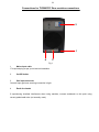
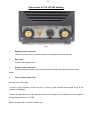
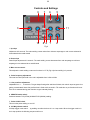
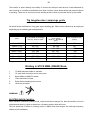
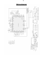
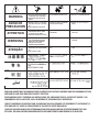
www.r-techwelding.co.uk
TIG200PDC DC TIG WELDER
OPERATION INSTRUCTIONS
www.r-techwelding.co.uk
Tel: 01452 733933
2
3
Thank you for selecting the R-Tech TIG200PDC Inverter DC Tig Welder.
The TIG200PDC has many benefits over traditional TIG welders, including pulse welding, slope
up/down and an industrial 60% duty cycle.
We want you to take pride in operating our TIG200PDC as much pride as we have taken in
making this product for you. Please read all information in this manual before operation
PLEASE EXAMINE THE CARTON AND EQUIPMENT FOR DAMAGE IMMEDIATELY
When this equipment is shipped, title passes to the purchaser upon receipt from the courier.
Consequently all claims for material damaged in shipment must be made by purchaser against
the transportation company used.
Please record your equipment identification below for future reference. This information can be
found on the data plate at rear of machine.
Product: TIG200PDC
Serial No. ___________________________________
Date of Purchase _____________________________
Where Purchased _____________________________
Whenever you request replacement parts or information on this equipment please always
supply information you have recorded above.
This product is covered by a 2 year parts and labour warranty; we will cover cost of collecting and
returning the item to you. External items, (torch, earth lead etc…) are covered by a 3 month warranty. Any
faults/damage found caused by a customer will be charged accordingly.
Pay particular attention to the safety instructions we have provided you for your protection
The level of seriousness to be applied to each section is explained below
WARNING
This statement appears where the information must be followed exactly to avoid serious personal injury.
CAUTION
This statement appears where the information must be following to avoid a minor personal injury or damage
to this equipment.
4
Introduction
The R-Tech TIG200PDC is a member of our field acclaimed family of welding products.
Premium features include:1
Inverter power source - more efficient to operate, provides smoother weld characteristics.
2
Pulse welding in DC Tig welding mode
3
HF Arc start - Easy arc striking and prolonged tungsten life
4
Slope up / slope down
5
Digital amp meter
6
Industrial 60% Duty cycle at 200 Amps @ 40℃
Recommended Processes
The R-Tech TIG200PDC is recommended for the Tig welding processes within its output capacity of 200 Amps
Equipment Limitations
The R-Tech TIG200PDC is protected from overloads beyond the output ratings and duty cycle as per machine
specifications with thermostat protection of the output coils and rectifiers.
Welding Capability - Duty Cycle
The R-Tech TIG200PDC is rated at 200 Amps at 60% duty cycle on a ten minute basis. If the duty cycle is
exceeded a thermal protector will shut machine off until the machine cools.
Technical Specifications
Model No.
Input
MMA
DC TIG
Gross Weight
R-Tech TIG200PDC
240V AC 50/60Hz
Fuse Slow-blow 32Amp
No-load Voltage
60V - 80V
Current Range
5A - 160A
Rated Output Current
160A
Duty Cycle
60%
No-load Voltage
60V - 80V
Current Range
5A - 200A
Rated Output Current
200A
Duty Cycle
60%
Up-Slope Time
0-5 Seconds
Down-Slope Time
0-5 Seconds
Pulse Frequency Range
0.5Hz - 25Hz
Gas Post Flow Time
1 - 10 Seconds
Arc Starting Mode
High Frequency
Pulse width
0.1-0.9
16 KG
Insulation
IP21S
Dimensions mm
425 x 195 x 310
5
Safety Precautions
Read entire section before starting installation
WARNING!
Electric Shock can kill - Only qualified personnel should perform this installation. Turn off input power at the fuse
box before working on this equipment. Do not touch electrically live parts. Always connect the machine to an
earthed mains supply as per national recommended standards.
Select suitable location
Place the welder where clean cooling air can freely circulate in and out of the front & rear louver vents. Dirt, dust
or any foreign material that can be drawn through vents into welder must be kept to a minimum. Failure to
observe these precautions can result in excessive operating temperatures which can lead to plant failure.
Grinding
Do not direct grinding particles towards the welder. An abundance of conductive material can cause plant failure.
Stacking
This machine cannot be stacked.
Transport - Unloading
Never underestimate the weight of equipment, never move or leave suspended in the air above people. Use
recommended lifting equipment at all times.
WARNING!
Falling Equipment can cause injury. Never lift welder with gas bottle attached. Never lift above personnel.
Tilting
Machine must be placed on a secure level surface or on a recommended undercarriage/trolley. This machine may
topple over if this procedure is not followed.
Environmental Rating
The welding power source carries the IP21S rating. It may be used in normal industrial and
commercial environments. Avoid using in areas where water / rain is around.
Read and follow the 'Electric Shock Warnings' in the safety section if welding must be performed
under electrically hazardous conditions such as welding in wet areas or water on the work piece.
6
Electrical Installation
WARNING!
ELECTRIC SHOCK CAN KILL
Machine grounding and High Frequency Interference Protection
This welder must be grounded to earth. See national electrical codes fro proper grounding methods.
The high frequency generator being similar to a radio transmitter may cause interference to radio, TV
and other electronic equipment. These problems may be the result of radiated interference. Proper
grounding methods can reduce or eliminate this.
Radiated interference can develop in the following ways
1
Direct interference from welder power source
2
Direct interference from the welding leads
3
Direct interference radiated from feedback into power lines
4
Interference from re-radiation by un-grounded metallic objects.
Keeping these contributing factors in mind, installing equipment as per following instructions should
minimize problems.
1
Keep the welder input power lines as short as possible and enclose as much of them as
possible in metal conduit or equivalent shielding. There should be a good electrical contact between
this conduit and ground (Earth).
2
Keep the work and electrode leads as short as possible. Tape the leads together where
practical.
3
Be sure the torch and earth leads rubber coverings are free from cuts and cracks that allow
welding power leakage
4
Keep earth lead connection to work in good condition - Clean area on workbench where earth
clamp is situated on a regular basis.
Input Connections
Make sure the voltage, phase and frequency of input power is as specified on machine rating plate
located at rear of machine.Have a qualified electrician provide suitable input power as per national
electrical codes. Makesure machine is earthed / grounded.
7
Make sure fuse or circuit breaker is correct rating for machine. Using fuses or circuit breakers smaller
than recommended will result in 'nuisance' shut off from welder inrush currents even if welding at low
amperages.
Failure to follow these instructions can cause immediate failure within the welder and void machines
warranty.
Turn the input power OFF at the mains switch & fuse box before working on this equipment.
Have a qualified electrician install & service this equipment.
Allow machine to sit for 5 minutes minimum to allow the power capacitors to discharge before
working inside this equipment. Do not touch electrically live parts
The TIG200PDC Inverter Tig Welder requires a 240V 50/60Hz 32amp fused supply.
It comes with a 3 metre mains cable attached.
Connect wires according to national coding.
Brown wire - Live
Blue wire - Neutral
Green/Yellow Wire - Earth (Ground)
Connecting to an Engine Driven Generator
If
connecting this machine to an engine driven generator please ensure
the following
Minimum Generator KVA Output - 7.5 KVA
continuous Generator to be fitted with AVR (automatic voltage regulation)
DO NOT USE ON A GENERATOR WITHOUT AVR
Connecting to a generator without the above minimum requirements will
invalidate your warranty.
8
Connections for TIG200PDC Rear machine connections
2
1x110V or 240V
4
1
3
Fig 1
1
Mains input cable
Fit required plug as per your electrical installation
2
On/Off Switch
3
Gas input connector
Connect input gas hose ensuring connection is tight
4
Earth for chassis
If experiencing localized interference when using machine, connect workbench to this point using
correct graded earth wire (not normally used)
9
Connections for TIG (GTAW) Welding
Fig 2
1
Negative power connector
connect Tig Torch Dinze to power connector by inserting and twisting until tight
2
Gas outlet
Connect the torch gas hose
3
Positive power connector +
Connect the earth lead to by inserting and twisting until tight and the earth clamp to work/
bench
4.
Torch control socket 7-Pin
Connect torch control plug
To avoid a High Frequency shock keep the Tig torch in good condition and replace if any of the
insulation is damaged.
Connect the gas input hose to gas regulator and use 'Pure Argon' Gas, available from local suppliers.
Set gas flow/pressure to 8-12 LPM.
Make sure gas bottle is secured to avoid injury.
10
Connections for STICK MMA (SMAW) Welding
Fig 3
1.
Negative power connector
Connect the earth lead to by inserting and twisting until tight and the earth clamp to work/bench.
2.
Gas Outlet - NOT used in MMA mode
3.
Positive power connector +
Connect the electrode holder by inserting and twisting until tight
4.
Torch switch plug - Not used in MMA mode
11
Controls and Settings
7
9
6
5
3
11
10
8 4 1
2
Fig 4
1. Up slope
Adjustment 0-5 seconds. The main welding current raises from minimum amperage to main current selected in
time selected when weld started
2. Down slope
Down-Slope adjustment 0-5 seconds. The main welding current decreases from main amperage to minimum
amperage in time selected when weld finished
3. Main current control
This adjusts the main welding current and is shown in L.E.D (Fig 4.9) when welding is in process.
4. Pulse frequency adjustment
This sets how often pulse will occur and is adjustable from 0.5Hz to 25Hz.
5. Gas post flow adjustment
Adjustable from 1 – 10 seconds. The gas keeps flowing after weld has finished, this cools & stops tungsten from
getting contaminated. Note: Gas pre-flow time is fixed at 0.5 seconds in TIG mode but no pre-flow time will occur
if the arc is restarted during post flow time as gas is already flowing.
6. MMA-TIG mode switch.
Switches between TIG (GTAW) & MMA STICK (SMAW) welding.
7. Pulse On/Off switch
This turns the pulse welding on and off.
8. 2/4 Way selector switch
2/4 Step trigger mode switch – tig welding can either be done in 2 or 4 step mode. When the trigger mode is in
the 2 step position the following sequence will occur
12
Press and hold the Tig torch switch to start sequence.
The machine will open gas valve to start flow of shield gas, after a 0.5 seconds pre-flow time to purge air from
torch hose the welding output of machine will be turned on and the arc will be started. After the arc is started the
output current will increase from the start (min) current to base (main) current in time selected by slope-up.
Release the Tig torch switch to end sequence.
The machine will now decrease output to finish (min) current in time set by slope-down, once at finish (min)
current the machine will stop output and the gas valve will continue to operate for the selected time (post flow)
Possible variations of this standard sequence are shown in diagram below. It is possible to press and hold tig
torch switch a second time during down slope time to restart. After the switch is pressed the output current will
raise to base (main) current
When the trigger mode is in the 4 step position the following sequence will occur
Press and hold the tig torch switch to start sequence.
The machine will open gas valve to start flow of shield gas, after a 0.5 seconds pre-flow time to purge air from
torch hose the welding output of machine will be turned on and the arc will be started. After the arc is started the
output current will be at start (min) current
13
This condition can be maintained as long as required.
Release the tig torch switch to go to step 2
The machine will now increase output to base (main) current in time set by slope-up.
Press and hold the tig torch switch when main weld is complete
The machine will now decrease the welding output current to finish (min) in down-slope time set. Once at finish (
min) output you can release the Tig torch switch to end weld the gas post-flow will continue to run for set time.
9
LED Display 3 digit LED meter is used to display the actual amperage (when welding).
10
Base current control, This adjusts the Base welding current,when you use at pulse function,please put
it lower than main(pulse current at pulse function).
11
Pulse width adjustment,this set show the rate of pulse current/base current,when you use the pulse
function.
Operating machine
SAFETY PRECAUTIONS
WARNING!
ELECTRIC SHOCK CAN KILL
Do not touch electrically live parts or electrode with skin or wet clothing. Insulate yourself from work
and ground Always wear dry insulating gloves
WARNING!
FUMES AND GASES can be dangerous
Keep your head out of fumes & gases produced from welding.
Use ventilation or exhaust to remove fumes & gases from breathing zone and general area.
14
WARNING!
WELDING SPARKS can cause fire or explosion
Keep flammable material away from work area.
Do not weld on containers that have held combustibles
WARNING!
ARC RAYS can burn
Wear eye, ear and body protection - Make sure work area is protected by proper shielding to
avoid injury to passers by.
Welding in TIG mode - No Pulse
1
Connect the Tig Torch to machine, connect earth lead to machine & work piece.
2
Set the TIG/MMA switch to TIG
3
Set Pulse Switch to Off position
4
Select 2 or 4 way torch operation
5
Connect Argon gas and set flow to approx 8-12 LPM
6
Set Gas post flow to 3 x diameter of tungsten width
7
Adjust main current to desired welding current
8
Press the Tig torch switch to start welding
Welding in TIG mode - with Pulse
1
Connect the Tig Torch to machine, connect earth lead to machine & work piece.
2
Set the TIG/MMA switch to TIG
3
Select 2 or 4 way torch operation
4
Connect Argon gas and set flow to approx 8-12 LPM
5
Set Gas post flow to 3 x diameter of tungsten width
6
Set Pulse On/Off switch to ON
7.
Adjust Pulse freq. to desired setting (how often pulse happens)
8.
Adjust main current(pulse) higher than base current.
9.
Adjust pulse width to desired setting.
10.
Press the Tig torch switch to start welding
15
The benefits of pulse welding is the ability to control the weld pool and amount of heat absorbed by
work resulting in a smaller heat affected zone which results in fewer deformations and reduced chance
of cracking. There are no set rules for pulse welding as this is down to personal choice by the welder.
Tig tungsten size / amperage guide
All values below are based on using pure argon shielding gas. Other current values may be employed
depending on the shielding gas and application
ELECTRODE RATINGS
Electrode Diameter
(mm)
2% Thoriated on DC(amps)
Red Tip - Grind to point
Zirconiated 0.8% Tungsten
on AC (amps)
White Tip - No need to
grind
Pure Tungsten on DC
(amps)
1.0mm / 0.040"
1.6mm / 1/16"
2.4 mm/ 3/32"
4.0mm / 5/32"
3.2mm / 1/8"
5 - 80
40- 150
140 - 250
240 - 400
380- 500
20 - 60
40- 100
80 - 180
160 - 250
220 - 320
30
80
130
180
240
4.8mm / 3/16"
6.4mm / 1/4"
500- 750
750 - 1000
280 - 390
360 - 525
300
400
Welding in STICK MMA (SMAW) Mode
1
Fit MMA electrode holder to machine
2
Fit earth lead to machine and to work piece
3.
Select MMA on MMA/TIG switch
4.
Place electrode in holder
5.
Select desired welding base current
6.
Strike arc and weld
WARNING!
ELECTRIC SHOCK CAN KILL
When machine is switched to MMA mode, output terminals are always live, take care and do not touch
electrode and earth by person at same time, otherwise electric shock will occur.
The foot pedal has no affect on welding current in MMA mode and the gas flow and high frequency
starting circuit is disabled.
16
Maintenance
Routine and periodic maintenance
WARNING!
ELECTRIC SHOCK CAN KILL
Turn the input power OFF at the mains switch & fuse box before working on this equipment.
Have a qualified electrician install & service this equipment.
Allow machine to sit for 5 minutes minimum to allow the power capacitors to discharge before
working inside this equipment.
Do not touch electrically live parts
1
Periodically remove the side/top panels of machine and clean out machine with a low pressure
dry air line paying particular attention to PC Boards, Fan blades, HF points
2
Inspect input and output cables & hoses for fraying, cuts & bare spots
3
Keep tig torch and cables in good condition
4
Clean air vents to ensure proper air flow and cooling
5
The fan motor has sealed bearings which requires no maintenance
Troubleshooting
Service & repair should only be performed by R-Tech welding trained personnel. Unauthorised repairs
performed on this welding equipment may result in danger or injury to the technician and machine
operator and will invalidate your warranty.
For your safety and to avoid electric shock, please observe all safety notes and precautions detailed
throughout this manual
The troubleshooting guide is provided to help you locate possible machine malfunctions
If fault / problem is not listed below check our Tig Welder Support page on our website
www.r-techwelding.co.uk/support.php
or contact R-Tech by phone. Contact details can be found on front of this manual and our website
17
Tig welding problems
●No output - Power light is not lit
Check machine on/off switch is in the 'on' position
Check Input power to machine
Check plug wiring Check mains trip / fuses
● No output - Fan runs - Power light is lit
Check torch connections are secure and torch switch operation, try replacing tig torch.
If you have a multi-meter check continuity between pins 1 and 2 on torch switch plug when pressing
torch switch
● No output - Power light is lit - Warning light is lit
Welding application may have exceeded recommended duty cycle, allow machine to cool
down until the warning light goes out.
●No output - Power light is lit - Gas at torch end when trigger pressed
Check torch condition - possible break in torch power cable - replace torch
● Machine keeps overheating - Warning light is lit on machine
Check if fan is running - if not contact R-Tech for repair Check the cooling vents for obstruction, blow
out machine with clean dry low pressure air supply. Check for adequate ventilation around machine
●Porosity in weld - No / low gas at torch tip
Check gas supply from gas bottle Check flow rate on regulator Check gas hose for restrictions Check
for draughts in local area, open doors etc Replace tig torch - may have gas restriction
●Poor weld penetration
Check condition of earth lead and clamp and ensure clamp is connection via a clean area on work
piece
Check condition of tig torch, try other tig torch
●Machine stuck on minimum amps when welding although higher amperage has been set
Make sure machine has not been set to 4-way operation as when in this mode when you press torch
switch you get minimum amps and when you let go of switch machine will go to maximum amps set.
Arc 'Flutters' when TIG welding
1
Tungsten electrode may be too large in diameter for the current setting.
2
Tungsten not sharp when in DC mode
3
Gas shielding flow may be low or high, check gas flow , reduce tungsten stick out beyond
ceramic
4
Check for leaks in torch & gas hoses
●Black areas along weld bead
.1. Clean any oily or organic contaminationfrom thework piece
2Tungsten electrode contaminated. Replace or sharpen
3 Check for leaks or contamination on gas hoses & connections.
4 Gas flow may be insufficient, Increase gas flow, reduce tungsten stick out from ceramic .
18
● Weak HF - Poor arc striking - welding output normal
1 Check torch and earth connections - is torch cable insulation in good condition.
2 Check for leaks or contamination on gas hoses & connections.
3 Gas flow may be insufficient, increase gas flow, reduce tungsten stick out from ceramic
4 Keep output cables short as possible
● HF spark is present at the tungsten electrode but unable to start welding arc, Machine has
normal welding output
1 Tungsten may be contaminated -replace or sharpen
2 The current may be set too low
3 Tungsten may be to large for process
4 Gas flow may be insufficient, increase gas flow, reduce tungsten stick out from ceramic
●No HF when torch trigger pressed, no blue spark between HF points
Examine and clean HF points with clean dry low pressure air line
HF PCB faulty - Contact R-Tech for repair
MMA Stick welding problems
●Stick electrode 'blasts off' when arc is struck
Welding current set to high, reduce amperage or use thicker electrode
Contaminated electrodes or material
●Electrode sticks in weld puddle
Welding current is set too low Arc is too short, keep electrode further away from work
●Excessive splatter
Too long an arc, keep electrode closer to work
●Poor penetration
Travel speed too fast
Too much welding current, reduce welding amperage
●Porosity in weld
Electrodes are damp
Arc too long, get electrode closer to work
19
Wiring diagram
● Do not touch electrically live parts or
WARNING
Spanish
AVISO DE
PRECAUCION
French
ATTENTION
German
WARNUNG
Portuguese
ATENÇÃO
● Keep flammable materials away.
● Wear eye, ear and body protection.
● Mantenga el material combustible
● Protéjase los ojos, los oídos y el
electrode with skin or wet clothing.
● Insulate yourself from work and
ground.
● No toque las partes o los electrodos
bajo carga con la piel o ropa mojada.
● Aislese del trabajo y de la tierra.
● Ne laissez ni la peau ni des vête-
ments mouillés entrer en contact
avec des pièces sous tension.
● Isolez-vous du travail et de la terre.
● Berühren Sie keine stromführenden
Teile oder Elektroden mit Ihrem
Körper oder feuchter Kleidung!
● Isolieren Sie sich von den
Elektroden und dem Erdboden!
● Não toque partes elétricas e elec-
trodos com a pele ou roupa molhada.
● Isole-se da peça e terra.
fuera del área de trabajo.
● Gardez à l’écart de tout matériel
inflammable.
● Entfernen Sie brennbarres Material!
cuerpo.
● Protégez vos yeux, vos oreilles et
votre corps.
● Tragen Sie Augen-, Ohren- und Kör-
perschutz!
● Mantenha inflamáveis bem guarda-
dos.
● Use proteção para a vista, ouvido e
corpo.
Japanese
Chinese
Korean
Arabic
READ AND UNDERSTAND THE MANUFACTURER’S INSTRUCTION FOR THIS EQUIPMENT AND THE CONSUMABLES TO BE
USED AND FOLLOW YOUR EMPLOYER’S SAFETY PRACTICES.
SE RECOMIENDA LEER Y ENTENDER LAS INSTRUCCIONES DEL FABRICANTE PARA EL USO DE ESTE EQUIPO Y LOS
CONSUMIBLES QUE VA A UTILIZAR, SIGA LAS MEDIDAS DE SEGURIDAD DE SU SUPERVISOR.
LISEZ ET COMPRENEZ LES INSTRUCTIONS DU FABRICANT EN CE QUI REGARDE CET EQUIPMENT ET LES PRODUITS A
ETRE EMPLOYES ET SUIVEZ LES PROCEDURES DE SECURITE DE VOTRE EMPLOYEUR.
LESEN SIE UND BEFOLGEN SIE DIE BETRIEBSANLEITUNG DER ANLAGE UND DEN ELEKTRODENEINSATZ DES HERSTELLERS. DIE UNFALLVERHÜTUNGSVORSCHRIFTEN DES ARBEITGEBERS SIND EBENFALLS ZU BEACHTEN.
● Keep your head out of fumes.
● Use ventilation or exhaust to
● Turn power off before servicing.
● Do not operate with panel open or
guards off.
remove fumes from breathing zone.
● Los humos fuera de la zona de res-
piración.
● Mantenga la cabeza fuera de los
humos. Utilice ventilación o
aspiración para gases.
● Gardez la tête à l’écart des fumées.
● Utilisez un ventilateur ou un aspira-
● Desconectar el cable de ali-
mentación de poder de la máquina
antes de iniciar cualquier servicio.
● Débranchez le courant avant l’entre-
tien.
teur pour ôter les fumées des zones
de travail.
● Vermeiden Sie das Einatmen von
Schweibrauch!
● Sorgen Sie für gute Be- und
Entlüftung des Arbeitsplatzes!
● Mantenha seu rosto da fumaça.
● Use ventilação e exhaustão para
remover fumo da zona respiratória.
● Strom vor Wartungsarbeiten
● No operar con panel abierto o
guardas quitadas.
● N’opérez pas avec les panneaux
ouverts ou avec les dispositifs de
protection enlevés.
● Anlage nie ohne Schutzgehäuse
abschalten! (Netzstrom völlig öffnen; Maschine anhalten!)
oder Innenschutzverkleidung in
Betrieb setzen!
● Não opere com as tampas removidas.
● Desligue a corrente antes de fazer
● Mantenha-se afastado das partes
serviço.
● Não toque as partes elétricas nuas.
● Não opere com os paineis abertos
moventes.
WARNING
Spanish
AVISO DE
PRECAUCION
French
ATTENTION
German
WARNUNG
Portuguese
ATENÇÃO
ou guardas removidas.
Japanese
Chinese
Korean
Arabic
LEIA E COMPREENDA AS INSTRUÇÕES DO FABRICANTE PARA ESTE EQUIPAMENTO E AS PARTES DE USO, E SIGA AS
PRÁTICAS DE SEGURANÇA DO EMPREGADOR.