1
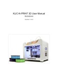
3D Printer
User Guide
1
Table of Contents
1. General
1.1 Main parts identification
1.2 What’s in the package
p3
p4~5
2. Assemble the 3D printer
p6~49
3. Operational checks and preprint setup
3.1 Sensors check
3.2 Print platform leveling and preheat
3.3 Loading filament
p51~52
p53~56
p57~58
4. Trouble shooting
* NOTE: THERE IS A VIDEO SERIES AVAILABLE ONLINE
FOR VISUAL REFERENCE FOR ASSEMBLY
The following safety precautions identifications are used in this manual
CAUTION:
Potentially hazardous situation to be avoided.
Failure to avoid may result in minor or moderate injury.
WARNING: Potentially hazardous situation to be avoided.
Failure to avoid may result in serious injury.
Beware of Hot Surface:
Some devices may radiate high temperature.
Be cautious and use safety gloves to avoid burns.
Turn off and lock-out system power before servicing.
Risk of electric shock or burn if failed to comply.
Wear safety glasses to avoid injury to your eyes.
ATTENTION
ELECTROSTATIC
SENSITIVE DEVICE
Use standard electrostatic discharge precautions
2
1.1
Main parts identification
Filament Spool(Sold separately)
Printer gantry
Print platform
Power On / Off
Main control panel
SD card slot
1) Rotary (for + / -)
2) Press (to select)
SD card insertion direction
(SD card not included)
Reset button
3
1.2
What’s in the box
Box-A
Box-D
Filament spool holder Set (DSA3302-U17)
Gantry
x1
Filament spool
support
Screws
this box:
+
x1
SCW0188
(HM4x22)
Gantry rail
x2
x5
x1
x2
Box-E
Model cooling fan
x1
Control Panel
x1
Box-B
Front Panel
Back Panel
x1
x1
Box-F
Print Platform
x1
Box-C
Left Panel
Right Panel
x1
x1
Top Panel
Bottom Panel & A/C Receptacle
x1
x1
4
1.2
What’s in the box
Box-G
Small nut (silver color)
MDT0139
Nut (silver color)
MDT0140
Torque coupling
MDT0142
Z-axis lead screw
x2
x4
x1
x1
Thick
Thin
“Thick” Nut
(bronze color)
MST0865
“Thin” Nut
(bronze color)
MST0866
Spring
Bearing
BER0038
Lower bearing support
MST0651
x1
x1
x1
x1
x1
SCW0039
(TM3x8)
x4
x5
PM-3PT04-P01
(TB3x12)
x40
x45
x1
x10
x3
Rod
MST0600
(for Left and Right panels)
x2
x2
Pre-assembled Rod
Timing belt (Long)
Timing belt (Short)
ETP0110
ETP0111
USB cable (type A to type B)
x1
x2
x1
Power
Spiral cut cable loom
Zip tie
x1
x1
x10
5
2
Assemble the 3D printer
This section will guide you through the process of building the
3D printer, step by step. Pre-assembled pieces can be located
from Boxes A to G.
6
2.1
Z-axis Lead Screw
Find the following accessories from: Box G
<1>
x1
x1
x1
x1
x1
Thick
Thin
Shorter non-threaded
end
Push up (compressing the spring
slightly) while threading the lead
screw (MST0625) up from the
bottom.
Longer non-threaded
end
Once done there will be a slight drag while
turning the lead screw.
A small amount of brass bushing (MST0866)
should still be exposed at the bottom. This is
called an Anti-backlash nut that is used to
remove play or slop in the Z-axis.
Anti-backlash nut
Small amount of
brass bushing is
still visible
7
2.1
Find the following accessories from: Box G
Z-axis Lead Screw
<2>
Rod
MST0600
(TB3x12)
x3
DSA3302-U07 Print platform
from Box-B
x2
x2
The Z lead screw can now be installed to
the print platform by using a 2.0mm hex
driver. The screws go in from the top
2.0mm hex
driver
(TB3x12)
2.1
<1>
2.2
DSA3302-U02 Back panel
from Box-E
Back Panel preparation
<1>
Start installing the 2 metal rods (MST0600)
to the back panel as shown on the right
2.5mm hex
driver
Rod
MST0600
8
2.2
Assemble to Back and Base Panels
<2>
2.2
<1>
Insert the print platform onto
the shafts of the back panel
as shown.
2.1
Turn the lead screw so that we
have approximately 2 inches
exposed from the top.
This will help to align with the
bearing.
<2>
Approx.
2”
2.2
<3>
The movement of the bearings and rods will
feel tight at this point, but we will tram (align)
the system later.
Slide the print platform upwards so that the
Z-axis lead screw inserts into the bearing.
9
2.2
Back and Bottom panels
Find the following accessories from: Box-G
<4>
x3
BER0038
MDT0142
MST0651
Bearing
Torque coupling
Lower bearing support
x1
x1
Install the bearing in to the lower bearing
support, and slide it onto the bottom of the
Z-axis lead screw (bearing facing upward).
BER0038
MST0651
2.2
<5>
Install the 3 screws from the back side to
secure the bearing support.
When tightening the support screws, push
lightly up to put a little tension on the
bearings.
2.0mm hex
driver
x3
10
x1
2.2
Now install the torque coupling to the bottom of the lead screw.
<6>
Positioning of torque coupling is not critical.
But at this moment, leave approx. 3mm distance
(for tramming procedure later) between bearing
support and the coupling.
Leave approx.
3mm gap for
now
Then tighten the coupling’s UPPER screw only.
MDT0142
Torque coupling
2.2
<7>
Next we are going to assemble the back panel
to the bottom panel.
Find the following accessories from: Box-G
It is recommended to turn the back panel on its
side and slide the bottom panel in place
(making an “L” shape)
SCW0153
(TB3x12)
x8
x2
DSA3302-U01 Bottom panel
from Box-C
Any flat surface
(eg. table top)
As you slide the bottom panel up you will need
to align the torque collar to the stepper motor
and the 2 vertical rods into the base.
11
2.2
<8>
Once seated (shown below), install 8pcs SCW0153 screws from the backside and
2pcs SCW0157 screws from the bottom side into the rods
2.5mm hex
driver
2.0mm hex
driver
SCW0157
(TM4x12)
x2
SCW0153
Install 8pcs SCW0157 (TM4x12)
screws from bottom side
(TB3x12)
x8
Install 8pcs SCW0153 (TB3x12)
screws from back side
2.2
With the back panel and bottom panel attached reposition the frame vertical to the upright position.
At this point we need to start to tram or square up the mechanics to ensure a smooth bind free motion
<9>
Any flat surface
(eg. table top)
12
2.2
<10>
Tramming Back and Base Assembly
We need to check the start friction, turn the torque coupling (that is at the bottom of the lead screw)
that we just installed left and right a few times, you will notice a heavy drag and possible binding on
the print platform just make a mental note of how much strength it takes to rotate the rod.
During this test the lower clamp to
stepper motor should not be tightened
so that the motor is not rotating and
only the drag of the rod is felt
2.2
<11>
Now to fix this problem, refer to diagrams 2.2a to 2.2c and loosen all the noted screws
in order.
Loosen them just enough that there is no contact with
the screw head and frame (Example on the right).
2.2a
2.0mm hex
driver
First loosen these 7
screws at the back
2.2b
2.0mm hex
driver
Then loosen these screws on
BOTH sides of print platform
13
2.2
<11>
2.2c
2.0mm hex
driver
Then loosen these 4 screws on
Underneath the build platform
By loosening the hardware the mechanical parts can adjust
to their natural tension-free positions alleviating binding.
2.2
<12>
Now following diagrams 2.2d to 2.2g for tightening order (The sequence is critical), go
through the hardware and re tighten the screws
2.2d
2.0mm hex
driver
Tighten these screws on
BOTH sides of print platform
2.2e
2.0mm hex
driver
Tighten these 4
screws at the back
14
2.2
<12>
2.2f
2.0mm hex
driver
Tighten these 4 screws on
Underneath the print platform
2.2g
2.0mm hex
driver
Finally, tighten these 3
screws at the back
After following the above tightening sequence the build platform will
move much easier and this can be verified by now turning the torque
coupling again and feeling a reduced amount of force needed.
There will always be some drag as this is calculated
to remove play and slop in the system.
If you are not satisfied, you can do the procedure again
Try turning the torque coupling again
after the above procedures
15
2.2
<13>
Now that the first components are trammed we need to secure the torque coupling to
the stepper motor.
Loosen the coupling from the lead screw and slide it down so that there is an equal
distance top and bottom from the lead screw and motor (shown below).
2 Equal
1
3
Loosen
Tighten
3
2.5mm hex
driver
Tighten
2 Equal
Then tighten both ends of coupling
Great job up to this step!
2.3
<1>
Next we are going to install the side panels. The side panels have a few things we need to
pay special attention to.
Both sides have the forward print platform vertical rods. This requires us to install the side
panel by sliding them down from the top.
The left panel (DSA3302-U06) has the A/C receptacle that needs to be attached from the
inside using some screws and nuts before we slide it down making installation easy to get to.
Find the following accessories from:
(TB3x12)
x2
SCW0157
(TM4x12)
x2
Box-G
Pre-assembled Rod
MDT0139
Nut
x2
(for Left and Right panels)
x1
DSA3302-U06
Left panel
from Box-F
SCW0153
x2
2.0mm hex
driver
A/C receptacle from
bottom panel
Pre-assembled Rod
(for Left and Right panels)
16
Place Side panel close to printer bottom
so we do not pull or damage the AC wires
from the power supply
2.3
<2>
Put the two screws (SCW0157) in from the outside of Left panel (DSA3302-U06) and then
slip the power receptacle over the exposed screws from the inside and install the nuts
(MDT0139) as shown below.
2.3
<1>
(Inner side)
2.5mm hex
driver
Assembled (seen from outer side)
7mm
wrench
A/C receptacle from
Bottom panel
DSA3302-U01
NOTE: the switch goes toward the front of the printer and the tapered side toward the
rear matching the panel cutout.
2.3
<3>
With the power switch / receptacle installed in the panel, it’s time to install the left panel by
carefully sliding the vertical rod down the front print platform bearing (pictured below right)
and making sure the rod aligns with its lower mount (pictured below right bottom).
2.3
<2>
2.2
<13>
17
2.3
Find the following accessories from:
Left panel installation
Box-G
<4>
SCW0153
(TB3x12)
x6
x4
Loosely install these screws without tightening them as we
need to align and tram the rods later (Example on the right).
2.3
<3>
2.0mm hex
driver
SCW0153
2.5mm hex
driver
2.3
<5>
(TB3x12)
x6
x4
Now check to make sure no wires are loose or damaged to the Switch / Power receptacle
to the power supply. Now well, we have easy access to the power supply, let’s set the
voltage.
Power from your home outlet varies depending on
where you live, for example, the USA is 110V
while Hong Kong is 220V. There is a switch on the
right side of the power supply marked 110-220V
(see above picture).
Set this switch to the appropriate position for your
region. If you are unsure about any of the above
steps or specification consult with a qualified
professional electrician.
18
2.3
Right panel installation
Find the following accessories from:
Box-G
<6>
SCW0153
SCW0157
Pre-assembled Rod
(TB3x12)
(TM4x12)
(for Left and Right panels)
x1
x8
x4
x4
DSA3302-U05
Right panel
from Box-F
SCW0153
x2
2.0mm hex
driver
Pre-assembled Rod
(for Left and Right panels)
2.3
Great job! Let’s move on to the right side panel. This one is easier than the left side, we
will install it in the same way as the left and loosely install the screws as we did on the right.
<7>
Sensor wires
2.3
<4>
2.3
<6>
Make sure as you are installing the
right panel the sensor wires do not
get pinched or caught on anything
19
2.3
<8>
SCW0153
2.0mm hex
driver
(TB3x12)
x6
x4
2.5mm hex
driver
Loosely install these screws without tightening them as we
need to align and tram the rods later (Example on the right).
2.3
With the panels loosely installed carefully lay the printer on it’s side
<9>
20
2.3
<10>
Now we need to install the lower rod securing screws SCW0157 (see below diagram).
Tighten these screws all the way as they will start to be the alignment points for
tramming the frame later.
SCW0157
(TM4x12)
x4
2.5mm hex
driver
2.3
<11>
We are done with the bottom so let’s turn the printer back upright. Great job so far,
let’s move on to next step.
21
2.4
<1>
We need to tidy up the wiring a bit before we move on. There are cutouts in the panels
that allow zip tie to pass through and secure the wiring. Loosely install zip ties in these
slots so we can start roughing the wires through the loops.
These zip tie slots
will be used
Routing the wires
1.
Picture 2.4a
Start by routing the Y-axis stepper motor wires (through the loop),
and the “Y-max” sensor wires down the back right corner cutout
(picture 2.4a).
Back stepper motor wires
through the loop
2. Next route the Z-axis stepper motor wires and “Z-max” sensor
wires (through the loop), together with the wires down from the back
right corner and through another loop (picture 2.4b).
“Y-max”
sensor
wires
Panel Cutout
3. Next route the “Y-min sensor wire, together with all the wires from
point 1 and point 2 mentioned above through the loop near the
front. Leave the loops loose as we will have more wires to pass
through later (picture 2.4c).
Picture 2.4a
“Y-max”
sensor
“Z-min”
sensor
Picture 2.4b
“Z-min”
sensor &
wires from
above
Z-axis stepper
motor & “Z-max”
sensor wires
“Y-min”
sensor
“Z-max”
sensor
Picture 2.4c
Picture 2.4c
Picture 2.4b
“Y-min” sensor
wires
22
Find the following accessories from:
2.5
Box-A
<1>
Gantry rail (Y axis rod)
X axis gantry
x2
x1
We need to install the Y axis rods onto the X axis gantry and
then install the XY gantry to the rear and side panels
Remove the protective plastic from the side rods, then remove the rod adapter washer and rod
support, by losing the set screw (see below diagram).
x2
Loosen this set screw on adapter
Rod adapter
2.0mm hex
driver
2.5
<2>
Unscrew at one end
Now carefully slide the rod through the two support bearings on the X axis gantry (see below
diagram and picture). The direction and side is not important as both sides are the same
Flat spot on the rod
Rod adapter
Once the rod is through both bearings, reinstall
the rod support washer and rod adapter
(note the flat spot on the end of the rod. This
lines up with the set screw on the rod adapter
while tightening)
23
2.5
<3>
Now we need to align the bearings by loosing the 8 cap screws (indicated below left) and
tighten them in a cross pattern (below right).
Loosen these 4 screws on each support bearing block
Cross pattern example when tightening
3
1
2
4
Now repeat this procedure on the other support bearing block
2.6
<1>
Now let’s install the gantry in the frame by loosely installing the 8 screws (SCW0153) and
2 nuts (MDT0140) to the rod supports.
2.5
<3>
2.4
<1>
24
2.6
<2>
It helps to align the rod supports parallel to the side panel before sliding it down.
(Note the extruder head goes toward the front and the fan toward the rear).
Loosely install MDT0140 (2pcs) with 12mm wrench at the back
MDT0140
SCW0153
x4
12mm wrench
(loosely install)
MDT0140
SCW0153
x4
(loosely install)
2.0mm hex
driver
2.6
<3>
Next we need to tighten the side panel screws and back panel screws that we left loose
on the previous steps
1 Start with the side panel screws on both
sides (not the gantry rod screws).
3
2 Next tighten the rear panel screws.
1
2
Tighten these side screws
(we left loose earlier) on
BOTH left and right panels
25
Tighten these side screws
(we left loose earlier) on
back panel
2.6
3 Then tighten gantry rod adapter nuts on the back.
<3>
4 Followed by the side rod supports
Rod support screws
(on BOTH Left and Right panels) 4
2.6
<4>
The gantry should glide back and forth and left and right if necessary an adjustment to
the inner gantry rods can be made to adjust the X axis length by losing the 3 rod set
screws (shown in below pictures) and sliding the gantry to the rear and adjusting till
smooth and re-tighten the 3 set screws.
26
2.7
<1>
The next step is to install the X-axis drive belt. Find the bag with 3 belts in Box-G.
There are 2 short belts and 1 long belt, we need to long belt for this step.
Picture 2.7b
Picture 2.7c, 2.7d
Picture 2.7e
Picture 2.7a
Find the following accessories from: Box G
Timing belt (Long)
ETP0110
Start first by laying the wires coming from the extruder head to the front of the printer to
give an unobstructed access to the belt area (picture 2.7a).
We need to route the belt around the motor sprocket with the long side toward the back
and the short end toward the front. The ribs of the belt are toward the inside or face
each other (picture 2.7b).
Picture 2.7a
Picture 2.7b
27
2.7
<1>
Now remove the screws on the right belt lock and lift up on the lock. Slip the belt into the
lock with ribs, matching the slots on the lock and the end of the belt flush with the end of
the lock (picture 2.7c and 2.7d).
2.0mm hex
driver
Picture 2.7c
Picture 2.7d
Slide the lock down and reinstall the screws. Run the other end of the belt threw the guide
block and around the pulley on the left side (picture 2.7e).
Picture 2.7e
Remove the 2 screws holding the tension lock (picture 2.7f) to the adjusting screw and lift
up. Now, turn the adjusting screw till the tension lock is all the way to the left (picture 2.7g).
2.5mm hex
driver
28
2.7
<1>
Picture 2.7f
Picture 2.7g
Lay the ribs of the belt in the tension lock. Lock the ribs to the slots just like the other
side (picture 2.7h). Slide the lock down and secure the two screws. Now slowly slide the
X-axis back and forth making sure the belt is moving freely around the motor and pulley
and in the guide block (picture 2.7i).
Picture 2.7h
Picture 2.7i
We need to adjust the tension on the belt now. Slide the extrusion head to the far right.
Now slowly turn the tensioning screw (picture 2.7j) till the belt, when twisted to 90 degrees,
feels slightly tight (picture 2.7k).
Picture 2.7j
Picture 2.7k
WARNING: DO NOT OVER TIGHTEN THE BELT
The belt is a timed belt (i.e. it has teeth like a gear so it will
not slip so they do need as much tension as a friction belt
29
2.8
<1>
We need to run all the wiring for the control panel now before we install the front and top
panels.
First, we need to bundle the top wires together and install an anti-chafe loom (spiral cut
cable loom) around them.
Find the following accessories from: Box G
Zip tie
Spiral cut cable loom
Referring to the picture 2.8a we need to gather the front fan wires (thin wires from the
front fan that magnets on), extruder heater (thick red wires), temperature sensor
(thin black wires coming from the extruder cover by the thick red wires), extruder
wires (multi-colored 4 wires), and the rear fan (thin red and black).
Extruder wires
Extruder heater wires
Temperature sensor wires
Rear fan wires
Front fan wires
Picture 2.8a
First zip tie the front fan, extruder and temperature sensor wires to the extruder top plate
(picture 2.8b). Bring them across the top, have the extruder motor wires and rear fan wires
come up and join the other wires (picture 2.8c).
Picture 2.8b
Picture 2.8c
30
2.8
<1>
Attach a few zip ties to hold them together and install the anti-chafe loom by wrapping
the wires (pictures 2.8d and 2.8e)
Picture 2.8d
Picture 2.8e
Cut the anti-chafe loom 5 inches from the end of the wires. Now move the extrusion
head to the front left position and lay the wire in the back panel slot, making an “L”
shape (picture 2.8f and 2.8g). This “L” shape will give the required slack for the print
head to move around and the wires not to blind.
Picture 2.8f
Picture 2.8g
With the “L” shape in place zip tie the wire loom down the back side on the 3 points cut
out for the zip tie on the back panel (picture 2.8h)
Picture 2.8h
31
2.8
<1>
Feed the loom in the bottom slot and guide it around the back right rod and tuck it under
the lower plate support (picture 2.8i) and bring it out the front.
Picture 2.8i
Now slide the print head to the back and locate the sensor wire on the left side (picture
2.8j). Run the wires toward the front and down zip tying it to the left panel where noted in
the picture (picture 2.8k).
Picture 2.8j
Picture 2.8k
Let’s switch to the right side, we need to gather the side motor (X-axis) and the right sensor
(picture 2.8l) and bring them down and zip tie them to the lower motor housing (picture 2.8m).
Then, with the print head all the way to the back bring the wires to the front and down zip
tie-in where noted in the figure.
Picture 2.8l
Picture 2.8m
32
2.8
<1>
Next unbundle the wires from the bottom of the print hot plate and feed them through the
most bottom right back cutout and bring them down and towards the front (pictures 2.8n
and 2.8o)
Picture 2.8n
Picture 2.8o
Now tighten the zip ties and tidy the wires up, making sure none of the wires bind or get
pinched and all come out the front (picture 2.8p).
Picture 2.8p
33
2.9
<1>
It’s now time to install the front panel. Locate and slide in the front panel with the plastic
parts facing toward the inside (picture 2.9a).
These plastic parts facing toward the inside of 3D printer
INNER SIDE
Picture 2.9a
2.8
<1>
Front Panel
Note: make sure not to pinch any wire in the front panel
34
2.9
Now locate SCW0153 (4pcs), SCW0143 (8pcs) screws and MDT0140 (2pcs) nuts.
<2>
Find the following accessories from: Box G
Nut (silver color)
MDT0140
(TB3x12)
x4
x8
x2
Install all screws loosely first. Once all are installed, tighten them up and install the 2 nuts
on the “Y” axis rods (picture 2.9b).
2.5mm hex
driver
Picture 2.9b
MDT0140
12mm wrench
(TB3x12)
2.0mm hex
driver
35
2.9
<3>
Next we need to install the “Y” axis belts and adjust them to each other.
Picture 2.9c, 2.9d
First, we need to loosen the set screws on the flex collars to free the shaft from each other.
Do not remove the screws. Just loosen them so the collar can rotate independently from
the motor shaft (pictures 2.9c and 2.9d)
Picture 2.9c
Picture 2.9d
Find the following accessories from: Box G
Timing belt (Short)
ETP0111
x2
36
2.9
<3>
Picture 2.9h
Picture 2.9e ~ 2.9j
Locate the two shorter belts (ETP0111). This step will be a lot like the belt installed on the
X-axis. First turn the adjusting screw so the belt tension block is toward the back (picture
2.9e).
Now remove the front belt lock and install the belt like we did before (picture 2.9f).
Picture 2.9e
Picture 2.9f
Now wrap the belt through the front idler pulley and thread it through. Then guide it back
around the rear motor pulley (picture 2.9g and 2.9h).
BACK
FRONT
Picture 2.9g
Picture 2.9h
37
2.9
<3>
Remove the tensioning belt block and lightly pulling on the belt, mesh the teeth with the
block and reinstall the block onto the tensioning screw (picture 2.9i).
Now slide the gantry towards the front making it easier to get to adjusting screw (picture 2.9j).
Adjust the tension on the belt as before till there is a light tension when twisting.
FRONT
Picture 2.9i
Picture 2.9j
Do not over tighten the belt, slide the gantry front to rear a few times and re-check the
tension.
Fantastic now we are going to do the same thing on the other side. Slide the extrusion head
to the left side and install the right belt following the same steps from the left side just flipped
around (picture 2.9k).
Picture 2.9k
Repeat same process for right belt
38
2.9
<3>
Now that both belts are installed slide the gantry front to rear a few times and adjust two
belts to match the looser of the two belt tension. Once done slide the gantry to approximately
the center, having the two set screws on the flex collars we loosened before facing up so
we can get to them easier.
Make sure the timing belts are
parallel and well aligned
Picture 2.9l
Now tighten the two set screws on the flex collars and test the motion front to rear there
will be a lot of drag but what we are checking for is that there is no binding in the motion
(picture 2.9l).
Recommended to fine tune the timing belts at below points
39
2.10
<1>
We are ready to install the top panel, there is a small hole on one of the sides near the center
cut out. This hole goes to the right side (see picture 2.10a for reference).
Find the following accessories from:
Box G
x16
Find the following accessories from:
Box D
Filament spool holder
Zip tie
x1
SCW0143
(TB4x14)
16pcs
2.5mm hex
driver
Hole on the right
Fit the top panel in place and make sure it seats flat and the small hole is to the right.
Now install 16pcs of SCW0143 screws to hold the top panel down (picture 2.10b).
Picture 2.10a
Picture 2.10b
40
2.10
<2>
The next step is to secure the extruder wiring harness to the top panel using a zip tie.
Move the extruder to the front left position and then slip a zip tie in the right hole and
secure up the wiring harness (pictures 2.10c and 2.10d). This creates enough slack in
the wiring harness to move around as well as keeping clear of moving parts.
Zip tie here
Picture 2.10c
Picture 2.10d
We will now install the filament spool support. The two upright supports are bolted to the
side panels with 4 SCW0188 screws (picture 2.10e). The two supports have an inside and
an outside if you look at where the two tubes come together and the plastic block there is
a slot for the axle to the seat, there is a flat side that stops the axle from moving side to
side. This flat side goes toward the outside (picture 2.10f). Tighten the two bolts using a
7mm wrench (pictures 2.10g and 2.10h).
Picture 2.10e
Picture 2.10f
41
2.10
<3>
Picture 2.10g
Picture 2.10h
The Spool drum slips on to the axle and sets into the two upright supports we just installed
(picture 2.10i).
Filament roll
(Sold separately)
Picture 2.10i
42
2.11
<1>
We are almost done with assembly! It’s time we wire up the control panel. Referring to the
diagrams we need to plug in the related cables, making sure to match the labels to position
and color to direction. This may look like a lot, but it’s really simple and we will do it in groups
one by one for a simple pain-free assembly (picture 2.11a).
Start with the position sensor wires, pay attention to the color vs pin position. There is a
total of 6 position sensors, 2 for each axis (picture 2.11b). It may help to cut the two side
zip ties to give more slack in the cables and once done re-tidy the cables and install new
zip ties.
Next is the two temperature sensors, one for the heating bed (HBP Thermistor) and one for
the extrusion head (Extruder Thermistor), these wires are black and only position is important
not direction (picture 2.11c).
Picture 2.11b
Picture 2.11c
43
2.11
<1>
Now it’s time for the stepper motors, these are labeled X, Y, Z, E0 for the given axis and
extruder. Note the color wire position when plugging in the 4 motors (picture 2.11d).
Picture 2.11d
Picture 2.11e
We are going to move to the terminal blocks start by turning the screws on blocks (picture
2.11e) D10, D9, D8 counterclockwise to open up the wire terminal. This allows us to insert
a wire and then by turning the screw clockwise it closes the terminal securing the wire
(picture 2.11f).
Picture 2.11g
Picture 2.11f
We are starting at block D10, which is the extruder heater. The two thick red wires need to
have the insulation carefully removed / stripped exposing the wires, remove approximately
7mm of insulation (picture 2.11g).
Now install one wire at a time. Insert the first wire into the first D10 slot and turn the screw
we just loosened clockwise till you feel the wire start to compress. Now turn the screw ½
a turn more. Do not over tighten the terminal blocks. Give the wire a tug and make sure
it feel secure and no stray wires are exposed (picture 2.11h).
Picture 2.11h
44
2.11
<1>
Now to block D9, this is the cooling fan output that is controlled by the G code to aid some
types of plastics in the printing process. We need to strip the wires back 7mm just like
before and install them the same way.
But there are two sets of wires, one for the front and one rear fan on the extruder and we
need to pay attention to the color: “Red is positive and Black is negative”.
Strip back 7mm of exposed wire and twist the pairs together, red to red, and black to black
(picture 2.11i).
Install the black wire set in it’s denoted spot first. These wires are a bit smaller so once you
start to feel the wires compress tighten one full turn.
Do the same for the red wire set next and lightly pull on the wires to make sure they are
secured (picture 2.11j).
Picture 2.11i
Picture 2.11j
Block D8 is the heating bed output (to heat the built platform). Strip back the wires 7mm
and install them the same way as before, noting the color / polarity to position. Tighten
one full turn past first contact and lightly pull the wires to make sure they are secured
(picture 2.11k).
Picture 2.11k
45
2.11
<2>
Great all that is left is to plug the DC power plug into the board and install the board cooling
fan wires (picture 2.11l). Strip back the fan wires 7mm, be careful as these wires
are small (picture 2.11m).
Board cooling fan wires
Picture 2.11l
Picture 2.11m
Loosen the top red and black terminal wires and slip the front board fan wires in matching
red and black. Then re-tighten the terminals (picture 2.11n). Now plug the power connector
to the main board (picture 2.11o) and make sure it seats flush (picture 2.11p).
Picture 2.11n
Picture 2.11o
Picture 2.11p
46
2.11
Now we need to attach the front control panel to the printer and tidy up the wiring.
<3>
Find the following accessories from:
Box G
SCW0039
(TM3x8)
x4
Zip tie
x4
Install the 4pcs SCW0143 screws in the front panel, leaving them slightly loose (picture 2.11q).
2.5mm hex
driver
x4
Picture 2.11q
47
2.11
Now we need to zip tie the loose wiring and tidy it up (picture 2.11r).
<3>
Picture 2.11r
Now install 4pcs SCW0039 screws from the inside (picture 2.11s and below diagrams), 2pcs
on the left, 2pcs on the right. Once done, tighten the 4 outer screws we previously installed .
2.0mm hex
driver
SCW0039
(TM3x8)
x4
Picture 2.11s
48
2.11
<3>
Congratulations, your 3D printer is now assembled. We still need to level the print bed and
check the functionality. This will be covered in the setup guide.
49
3
Operational checks and preprint setup
This section will guide you through the process of operations checks
and preprint setup
50
3.1
<1>
Now that the printer is built we need to perform an operational check of the sensors and
motors and other components, then a Preprint setup.
First manually move the extrusion head to the approximate center of the print platform
(picture 3.1a). Then turn the Z axis lead screw by hand to lower the print platform to about
1 inch (or about 25mm) below the extrusion head (picture 3.1b).
Picture 3.1a
Picture 3.1b
Now look over all the wiring, making sure nothing has been pinched or damaged during
assembly. Attach the A/C power cable to the left side port with the power switch in the
off position (picture 3.1c). Make sure the power plug matches to the type of receptacle
appropriate to your region, as well as double check that the main A/C power voltage was
set properly in the assembly process for 110 or 220 A/C input (Consult with a professional
if in doubt).
Turn off and lock-out system power before servicing.
Risk of electric shock or burn if failed to comply.
Plug in the power cable and turn on the main switch, the LCD will light up and after a few
seconds and provide a main screen readout. This main screen shows the temperature of
the heating bed, extruder and position of the gantry (picture 3.1d).
Picture 3.1c
Picture 3.1d
51
3.1
<1>
The first check is to look at the position sensors (total 6 sensors) to make sure they have a
red LED light on (pictures 3.1e ~ 3.1i).
Picture 3.1e
(Right panel)
Picture 3.1f
(Right panel)
Picture 3.1g
(Back panel)
Picture 3.1h
(Gantry’s right block)
Picture 3.1i
(Gantry’s left block)
When the sensor is triggered the LED light goes out (this is why we moved the extruder
to the middle). If you don’t have a red light on one of the sensors turn the power off and
make sure the print head or print platform is away from that sensor as well as check that
the 6 sensors wires were plugged in following the color direction per the diagram in the
control panel’s assembly section.
52
3.2
<1>
Next we need to check the motors for proper direction. Using the auto home feature, but first
on the back of the printer we need to set the Z axis top sensor to the lowest setting.
Do this by turning the knob counterclockwise till it stops (picture 3.2a).
Picture 3.2a
Auto Home position check
1) Rotary (for + / - or navigate)
2) Press (enter / to confirm selection)
Reset button
We are going to use the menu system to auto home the printer watching the direction the
print head moves. Facing the front of the printer the left side is the one with the power
cable.
Select Auto Home
To enter the menu, press the right knob in. To move within the menu rotate the knob.
Main button --> Prepare --> Auto home.
Once we give the command to auto home, the print head will:
--> first move to the left --> then to the front --> followed by the print bed moving up.
Be prepared to quickly turn off the main power switch if it does not move left-->front-->up,
or the motors continue to try and move the print head after it has moved to its extent.
The motors if going the wrong direction or if a sensor is plugged in the wrong position will
cause damage. If this happens refer to the troubleshooting guide.
53
3.2
Now the 3D Printer is homed and knows its position relative to the print bed.
<2>
Next we need to level the print bed to the extrusion head. To do this we need to manually
set the bed level and adjust the rear sensor followed by manual adjustment.
We need to enter the menu and lower the print bed so we can set its level. Press the knob
to enter the menu and go to prepare scroll down to move axis scroll to 1mm, then scroll to
Z. Slowly rotate the knob to the right lowering the print bed about 4 inches.
Menu --> Prepare --> Move axis --> 1mm --> Move Z --> rotate to move down
Once the bed has been lowered turn the printer power off. There are 4 bolts around the
print bed that adjust its height. Using a straight edge such as a ruler, adjust the bed using
a 7mm wrench to lower the printing plate level to the clear side arms (picture 3.2b & 3.2c).
Use these screws to fine tune
7mm wrench
Picture 3.2b
Picture 3.2c
Picture 3.2d
Once a mechanical level has been achieved turn the printer on and perform an Auto home
function from the menu, just like we did before. The print bed will move up close to the
extrusion head, but we need to dial the setting in a little closer. We need to adjust the
back sensor by turning the knob clockwise we will do this in increments equal to “an hour”
on a clock. Imagine the back knob is a clock with 12 hours showing we will turn the knob
that is equal to one hour, i.e. little adjustment (picture 3.2d).
54
3.2
<3>
You will need two business cards (or cards or about the same thickness) for this procedure.
We will use this to measure the distance from the print bed to the extruder nozzle and set
the height.
Set the 2 business cards on top of each other on the glass print surface under the nozzle.
The procedure is as follow:
- Turn the knob clockwise “one hour” and perform an auto home.
- Keep doing this moving the back knob by “one hour” increment each time till the nozzle
touches the business cards and you can feel a light drag if you try and move the business
cards (pictures 3.2e and 3.2f).
Picture 3.2f
Picture 3.2e
Once you have the back sensor set to two business cards height, turn off the printer and
remove the two business cards. We will now set the level and fine tune the setting.
With the power off slide one business card between nozzle and the bed, using a 7mm
wrench, loosen the left front bolt that adjusts the bed till one business card just fits between
the nozzle and the bed. Now manually move the extrusion head to the back right and do
the same procedure. You may find you have to adjust the bed up or down.
Slid the head forward to the right front and adjust the right front bed bolt till the card just
fits, and now the back left position and bolt follow the same procedure. Once complete
redo the sequence starting at the left front again, as adjusting one slightly throws the
others off. Once this is set, it rarely needs to be adjusted again (pictures 3.2g and 3.2h).
Checking Sequence
Picture 3.2g
Picture 3.2h
55
3.2
<3>
Now we need to check the temperature sensors and heaters we are going to perform a
preheat to make sure the sensors and heaters are working ok.
Turn on the 3D printer and look at the screen. The top line shows the extruder temperature
on the left and the heating bed on the right. The first number is the current temperature
both the bed and extruder should show within a few degrees of each other, and the number
after the slash is the commented temperature that should show Zero (pictured below).
Extruder temperature
Heating bed temperature
Commented
temperature
Current
temperature
Current
temperature
Commented
temperature
Perform an auto home function first, then enter the menu by pushing the knob as follow:
Menu --> Prepare --> Preheat PLA
Once you select the preheat you will hear the fans come on and the temperatures on the
main screen will indicate a requested temperature on the right side of each slash, showing
180 and 70 respectively (picture 3.2i). The numbers on the left of each slash will start
climbing to match the requested amount.
Picture 3.2i
The extruder will heat very fast, the bed will take a few minutes to stabilize. What you want
to see is the current temperature verses requested (you should see them rise to match the
requested and stabilize, shown in picture 3.2j). Sometimes the temperature over shoots a
few degrees and comes back down. What you don’t want to see is the current temperature
climb past the requested temperature and have a runaway. If it goes over by 7 degrees or
more shut down the printer and refer to the troubleshooting guide.
Picture 3.2j
56
3.3
<1>
Now we need to load filament. PLA is recommended for new users. The 3D printer uses 1.75
filament and is a top load system.
Lift off the spool axle and drum, unthread the drum end cap and slide your filament spool
onto the drum and replace the axle (picture 3.3a). Install the Axle and spool so the filament
unwinds to the front of the printer (picture 3.3b).
Filament roll
(Sold separately)
Picture 3.3a
Filament unwinds to the front of the printer
Picture 3.3b
57
3.3
<2>
Perform a preheat as the extruder will need to be hot to load the filament. Now cut off
about 3 inches of the filament, removing any bends or kinks and insert the filament into
the extruder (picture 3.3c). You will need to push the filament past the roller, it will take
a little pressure for it to compress the tension spring and this is normal. Once past the
roller use tweezers to help guide the filament into the center of the white seal (picture
3.3d) and continue to push the filament down till you see some come out of the print
head.
Filament
For cutting off filament
Filament entry point
Roller
Gate cutter
For guiding filament into extruder
Center of white seal
Tweezer
Picture 3.3c
Picture 3.3d
Congratulations! Your printer is ready to print. Please refer to the operations guide and
videos to understand the operation of the printer and software.
Insert SD card per direction shown
(SD card not included)
58
4
Trouble Shooting
The trouble shooting guide is a live dynamic and updatable document, that can be
accessed online under the files tab of the 3D printer on www.HobbyKing.com
There is also an active forum on http://www.rchouse.com/ dedicated to the HobbyKing
3D printer
Assemble,tips and tricks, trouble shooting video series is also available on YouTube
under the HobbyKingLive channel.
59
PRM0282