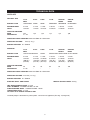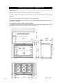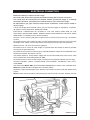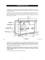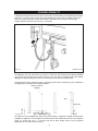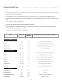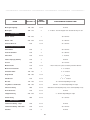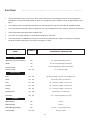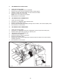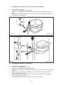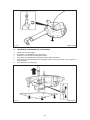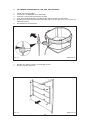
1
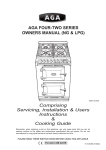
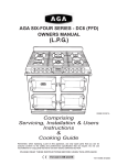
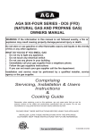
AGA SIX-FOUR SERIES - DC6 (FFD)
OWNERS MANUAL
DESN 512387
Comprising
Servicing, Installation & Users
Instructions
&
Cooking Guide
PLEASE READ THESE INSTRUCTIONS BEFORE USING THIS APPLIANCE
INSTALLER: LEAVE THESE INSTRUCTIONS WITH THE APPLIANCE
CUSTOMER: KEEP THESE INSTRUCTIONS FOR FUTURE REFERENCE
For use in Australia
05/13 EINS 514241
CONTENTS
SECTION
PAGE
INSTALLATION SECTION
3
INSTALLATION
TECHNICAL DATA
FITTING AND PRODUCT DIMENSIONS
ELECTRICAL CONNECTION
CONNECTING TO GAS
COOKER STABILITY
PRESSURE TESTING
LEVELLING AND MOBILITY WHEELS
FITTING OF HOTPLATE CASTINGS AND PAN
SUPPORTS
SPLASHBACK
USERS GUIDE
4
5
6
7
8
9 - 10
10
11
12 - 16
16
17
GENERAL INFORMATION
SAFETY PRECAUTIONS AND HINTS
PRODUCT VIEW
CONTROL PANEL
GAS HOTPLATE
TO FIT PAN SUPPORTS
GRIDDLE PLATE
SETTING UP THE COOKER FOR USE
SIMMERING OVEN
SIMMERING OVEN RECIPES
THE GRILL
THE OVENS
OVEN COOKING GUIDE
THE MINUTE TIMER
AUTOMATIC COOKING CONTROL
CLEANING AND CARING FOR YOUR COOKER
SERVICING SECTION
18
19
20
21
22
24
25
26
27
28
32
33
34
39
40
42
- 23
- 31
- 38
- 41
- 47
48
SERVICING
WIRING DIAGRAM
49 - 58
59
2
Installation
Section
CAUTION: THIS UNIT IS HEAVY, PROPER EQUIPMENT AND ADEQUATE MAN
POWER MUST BE USED IN MOVING THIS RANGE TO AVOID DAMAGE TO THE UNIT
OR THE FLOOR.
Remember, when replacing a part on this appliance, use only spare parts that you can be
assured conform to the safety and performance specification that we require. Do not use
reconditioned or copy parts that have not been clearly authorised by AGA.
3
INSTALLATION
PLEASE READ THESE INSTRUCTIONS BEFORE INSTALLING OR USING THIS
APPLIANCE.
THIS APPLIANCE SHALL BE INSTALLED BY AUTHORISED PERSONS AND IN
ACCORDANCE WITH THE MANUFACTURER’S INSTALLATION INSTRUCTIONS, LOCAL
GAS FITTING REGULATIONS, MUNICIPAL CODES, ELECTRICAL WIRING REGULATIONS,
AS5601/AG601 - GAS INSTALLATIONS AND ANY OTHER STATUTORY REGULATIONS.
PRIOR TO INSTALLATION, ENSURE THAT THE LOCAL DISTRIBUTION CONDITIONS
(NATURE OF GAS AND GAS PRESSURE) AND THE ADJUSTMENTS OF THE APPLIANCE
ARE COMPATIBLE.
THE GAS ADJUSTMENT CONDITIONS FOR THIS APPLIANCE ARE STATED ON THE DATA
PLATE WHICH IS SITUATED IN THE RIGHT HAND VENT SLOT AT THE BASE OF THE
APPLIANCE.
The appliance wiring diagram is situated on the back panel.
The appliance is not connected to a combustion products evacuation device. It shall be installed
and connected in accordance with current installation regulations. Particular attention shall be
given to the relevant requirements regarding ventilation.
It should be in accordance also with any relevant requirements of the Gas Region and Local
Authority.
On completion test the gas installation for soundness and purge. Leak testing of the appliance
shall be conducted according to the manufacturers instructions.
NOTE: Use soapy water on new gas connections to ensure there are no gas leaks.
WARNING - ELECTRIC SHOCK HAZARD
It is the customers responsibility to contact a qualified installer to make sure the electrical
installation is adequate and in conformance with SAA ELECTRICAL WIRING RULES AS 3000.
Take special care when cutting hole in walls or floors. Electrical wires may be behind the wall or
floor covering and could cause an electrical shock if you touch them.
Locate any electrical circuits that could be affected by the installation of this product and
disconnect power circuit.
Electrical earth is required on this appliance.
Do not use an extension lead with this appliance.
Check with a qualified electrician if you are not sure the appliance is earthed properly.
Failure to follow these instructions could result in death or serious injury.
The appliance is designed for the voltage stated on the data plate.
The AGA Six-Four Series - DC6 is supplied from the manufacturers in a fully tested condition.
Check the operation of the appliance to ensure the hotplate burners ignition operates correctly
or individual burners and in combination with other burners. Check flame picture and flame
stability.
Check oven elements heat up and that ovens reach temperature.
4
TECHNICAL DATA
HOTPLATE
NATURAL GAS
R.H.F.
R.H.R.
L.H.R.
BURNER TYPE
L.H.F.
WOK
ULTRA-RAPID
RAPID
RAPID
MAXIMUM HEAT
INPUT
4.2 kW
15 MJ/hr
3.3 kW
12 MJ/hr
3.3 kW
12 MJ/hr
INJECTOR MARKING
MAIN
72X
SECONDARY
2 x 112
155
-
155
-
SEMI-RAPID
CENTRE
FRONT
SEMI-RAPID
CENTRE
REAR
ULTRA-RAPID
1.95 kW
7.0 MJ/hr
1.95 kW
7.0 MJ/hr
4.2 kW
15 MJ/hr
118
-
118
-
180
-
PRESSURE POINT POSITION: REAR RH SIDE OF HOTPLATE
PRESSURE SETTING:
1kPa (4” w.g.)
BURNER IGNITION: H.T. SPARK
PROPANE
BURNER TYPE
MAXIMUM HEAT
INPUT
L.H.F.
R.H.F.
WOK
ULTRA-RAPID RAPID
RAPID
CENTRE
CENTRE
FRONT
REAR
SEMI-RAPID SEMI-RAPID ULTRA-RAPID
4.2 kW
15 MJ/hr
(300 g/h)
(0.59 l/h)
2.7 kW
9.6 MJ/hr
(190 g/h)
(0.37 l/h)
2.7 kW
9.6 MJ/hr
(190 g/h)
(0.37 l/h)
1.75 kW
6.3 MJ/hr
(125 g/h)
(0.246 l/h)
1.75 kW
6.3 MJ/hr
(125 g/h)
(0.246 l/h)
4.2 kW
15 MJ/hr
(300 g/h)
(0.59 l/h)
85
-
85
-
65
-
65
-
105
-
INJECTOR MARKING
MAIN
46
SECONDARY
2 x 66
R.H.R.
L.H.R.
PRESSURE POINT POSITION: REAR RH SIDE OF HOTPLATE
PRESSURE SETTING: 2.75 kPa (11” w.g.)
BURNER IGNITION: H.T. SPARK
ELECTRIC GRILL AND OVENS
WEIGHT OF APPLIANCE: 220 kg
TOP OVEN POWER RATING - 2.2 kW
GRILL ELEMENT - POWER RATING 2.45 kW
SLOW COOKING OVEN - POWER RATING 1.0 kW
LOWER OVEN (FAN) - 2.2 kW
240 VOLT 50 Hz SINGLE PHASE 30 AMP
The data plaque is located on a pull out plate - lower front of appliance (See Fig. 10, Page 20).
5
FITTING AND PRODUCT DIMENSIONS
Any side wall above the cooker on either side shall be not less than 60mm horizontally from the
cooker (Fig. 1).
Surfaces over the top of the cooker must not be closer than 650mm.
A minimum clearance of 1000mm must be available at the front of the cooker to enable it to be
serviced.
The vent slots in the back of the top plate must not be obstructed.
The cooker must stand on a firm and level surface. We recommend that any soft material such
as linoleum is removed.
PLEASE NOTE WHEN FITTING A COOKER HOOD
If a cooker hood is to be fitted, we only recommend the 6-4 Series CH900 cooker hood. It must
be installed at a height of at least 800mm above the hotplate.
DESN 512388 C
Fig. 1
6
ELECTRICAL CONNECTION
Electrical earthing is required on this range.
Disconnect the power to the junction box before making the electrical connection.
This range must be connected to an earthed, metallic, permanent supply or a earthing
connector should be connected to the earth terminal or wire lead on the range.
Do Not earth to gas pipe. Failure to follow these instructions could result in death or
serious injury.
A three-wire single phase 240-volt, 50-Hz, AC-only electrical supply is required on a separate,
30-amperes circuit, fitted with a double-pole isolator.
ELECTRICAL CONNECTION IS LOCATED AT THE TOP RIGHT HAND SIDE OF THE
APPLIANCE, BEHIND SIDE PANEL. DURING INSTALLATION REMOVE THE RIGHT HAND
SIDE PANEL TO CONNECT ELECTRICAL SUPPLY.
Remove 3 screws securing side panel to gain access to mains terminal. See Fig. 3 for location
of cover.
Remember that the mains electrical cable must be routed through the grommet at the rear right
hand side of the cooker, near the top, before connecting to the mains terminal connection.
REFER TO FIG. 2 for wire connection to appliance.
Remember that an excess of cable length is required inside the cooker to allow for possible
servicing of the spark generator.
Remember that an excess of cable length is required behind the cooker for the withdrawal of the
cooker from between the kitchen units etc.
The cooker requires a 30 amp power supply and must be connected to the mains with a cable
which complies with SAA Wiring Rules AS 3000.
Remember that an excess of cable length is required for the possible withdrawal of the range.
ALWAYS DOUBLE CHECK CONNECTIONS AND ENSURE TERMINALS ARE FULLY
TIGHTENED.
THE ISOLATOR MUST NOT BE POSITIONED IMMEDIATELY ABOVE THE COOKER, BUT
MUST BE SITED WITHIN 2 METRES OF THE APPLIANCE.
Replace the right hand side panel once electrical connection has been made and replace fixing
screws.
NOTE: Ensure that the insulation card covering the mains terminal is in place, between the side
Fig. 2
DESN 513312
7
CONNECTING TO GAS
This appliance can be connected with rigid piping as specified in AS5601 table 3.1 or with a
flexible hose which complies with AS/NZS1869, class B or D and in accordance with AS5601 for
a high level connector.
To allow ease of servicing and cooker mobility, an approved flexible 4ft hose should be fitted .
Supply piping should not be less than R 1/2 (1/2” BSP). Connection is made to the R 1/2 (1/2”
BSP) female threaded entry in the inlet block located just below the hotplate level on the rear
right hand side of the cooker.
Fig. 3
DESN 513190
The gas connector must be fitted to the wall in the shaded area dimensioned in Fig. 4. Take into
account that it must be possible to pull the cooker forward sufficiently for servicing. Ensure
flexible hose is not trapped between cooker back panel and rear wall. Ensure hose is routed
within the shaded area and away from the shielded oven vent. The flexible hose must be in
accordance with the relevant standards.
IMPORTANT: THE GAS SUPPLY CONNECTION AT THE WALL MUST NOT PROJECT OUT
FROM THE WALL BY MORE THAN 45mm, SO THAT IT DOES NOT FOUL WITH THE BACK
OF THE COOKER.
Check for gas soundness after connecting the appliance.
8
COOKER STABILITY
A stability bracket shall be secured firmly to the fabric of the building. For positioning of bracket
(See Fig. 3). A safety chain should also be anchored firmly to the wall and cooker to prevent
strain on the gas connection, when the cooker is withdrawn for servicing. When fitting a
stability bracket and chain refer to Fig. 3, 3A and 3B.
Fig. 3A
DESN 513188
The cooker must have an anti-tip bracket correctly installed as per these instructions. If you pull
the appliance out from the wall for any reason, make sure that the device is properly engaged
when you push the cooker back against the wall. If it is not, there is a possible risk of the cooker
tipping over and causing injury if you or a child stand, sit or lean on an open door.
If disconnection of the restraining chain is necessary then ensure restraining chain is reattached
as appliance us relocated in its original position.
CENTRE LINE OF
COOKER
WALL
BRACKET
Fig. 3B
FLOOR
To reduce the risk of tipping, the range must be secured by a properly installed anti-tip bracket
supplied the appliance. The bracket must be fitted within the shaded area shown in the diagram
using 2 x screws (No. 10 x 1 1/4) fixed in the wall or floor, longer screws may be required
depending on the wall or floor covering.
9
POSITION OF GAS BAYONET ON WALL (locate in shaded areas)
IMPORTANT: THE GAS SUPPLY CONNECTION AT THE WALL MUST NOT PROJECT
OUT FROM THE WALL BY MORE THAN 45MM, SO THAT IT DOES NOT FOUL WITH THE
BACK OF THE COOKER.
Fig. 3B
DESN 512390
PRESSURE TESTING
The pressure test point is situated at the rear right hand side of the hotplate.
Place the wok burner head, burner cap and ring into position on the hotplate. Light the burner
by pushing in the appropriate control knob, and turning it anti-clockwise to the full on position.
For Natural Gas appliance, manifold pressure is 1kPa (4” w.g.)
For LPG appliance (propane only), manifold pressure is 2.75 kPa (11” w.g.).
Turn off the taps, disconnect the pressure gauge and refit burner head.
The gas regulator is attached to the rear panel at the rear left hand side of the appliance, just
below hotplate level.
10
LEVELLING AND MOBILITY WHEELS
INSTALLATION AND LEVELLING
The DC6 is designed to stand on a flat and level surface, however any unevenness may be
overcome by adjusting the four levelling feet at each corner of the base plate. The adjusting
screws are accessed by removing left and right hand hotplate castings (See section ‘To Remove
Hotplate Castings - Servicing Section Page 50). To raise the cooker turn screw clockwise, to
lower turn screw anti-clockwise.
Fig. 5
DESN 512391 B
There are rollers on the base of the cooker to allow for positioning.
When the cooker is in the correct position the four levelling feet can be adjusted to level the
cooker. The feet must be lowered enough to prevent the cooker rolling out of position. (See Fig.
5).
11
FITTING OF HOTPLATE CASTING AND PAN SUPPORTS
HOTPLATE CASTINGS
1. Attach earth cable from centre of casting to cooker chassis and locate over burner bodies.
Repeat for LH and RH castings and that the gaskets are fitted where the outer castings
overlap centre castings. Ensure that earth cables are attached. (See Fig. 6A).
Fig. 6A
DESN 512400 A
2. Secure castings using 8 profiled fixing nuts. DO NOT OVERTIGHTEN. (See Fig. 6B).
Fig. 6B
DESN 512393 C
12
3. Fit and secure six burner rings using M4 screws on rear left hand, front centre, front right
hand and rear right hand burners. Use No. 6 3/8 screw on front left hand and centre rear
burners. (See Fig. 6C).
NOTE: The fitting of the LH and centre burners are the same as shown in Fig. 6B.
Fig. 6C
DESN 512419 A
4. Position burner caps onto burner bodies. (See Figs. 7A, 7B, & 7C).
ULTRA RAPID BURNER
Fig. 7A
WOK BURNER
DESN 513714
DESN 513512
13
ASSEMBLY OF RAPID AND SEMI-RAPID BURNERS
BURNER CAP
BURNER HEAD
ELECTRODE
Fig. 7B
DESN 511618
FITTING BURNER CAP - RAPID AND SEMI-RAPID BURNERS
BURNER CAP
RETAINING LUGS
Fig. 7C
DESN 511617
14
5. Fit the pan supports in the following order. The pan supports are marked on the underside to
correspond to the markings below. The pan supports must locate in the recesses in the
hotplate casting. (See Fig. 8A and 8B).
Fig. 8A
DESN 512995 A
Fig. 8B
IMPORTANT
It is VERY for the performance and reliability of the hob that the pan supports are fitted in
accordance with the AGA-SIX FOUR SERIES - DC6 OWNERS MANUAL.
To help identify the correct location of the pan supports, the centre rear pan support has been
uniquely designed with a tag as shown. This pan support must be fitted in the rear centre position
with the tag pointing towards the back of the appliance.
15
Fig. 8C
DESN 513716
TO ADJUST PAN SUPPORT LEVEL
1.
2.
3.
4.
Loosen retaining nut using 8mm spanner (See Fig. 8C).
To prevent rocking adjust the pan support using 2.5mm allen key.
Check pan support is level with opposing pan supports.
Retighten retaining nut.
HANDRAIL FITTING
1.
2.
Position handrail assembly onto locating studs at each end of facia. Ensure the grub screw
at each end of the hand rail is facing downwards.
Push handrail assembly fully against facia and lock in place by tightening 2 grub screws (2
1/2mm). (See Fig. 6A).
SPLASHBACK
1. Locate tabs on rear of splashback assembly, into the bracket on the upper rear of the cooker.
(See Fig. 9).
Push fully into place.
Fig. 9
DESN 512394
16
Users
Guide
17
GENERAL INFORMATION
As responsible manufacturers we take care to make sure that our products are designed and
constructed to meet the required safety standards when properly installed and used.
IMPORTANT NOTICE Any alteration that is not approved by Aga could invalidate the approval
of the appliance, operation of the warranty and could affect your statutory rights.
In the interests of safety and effective use, please read the following instructions before using
your new Aga appliance.
The use of gas on a cooking appliance results in the production of heat and moisture in the room
in which it is installed. Ensure that the kitchen is well ventilated, keep the natural ventilation holes
open or install a mechanical ventilation device (mechanical extractor hood).
Prolonged intensive use of the appliance may call for additional and/or more effective ventilation,
for example, opening of a window, or, increasing the level of mechanical ventilation where
present.
Installation must be to local and national wiring regulations and carried out by a qualified
engineer, from an authorised distributor.
A little smoke and some odour may be emitted when first switched on. This is normal and
harmless (from oven lagging and starch binder on the element insulation) and will cease after a
short period of use.
Your appliance has a gas hob, three electric ovens; the lower right hand oven is a slow cooking
oven, the upper right hand oven is a conventional oven.
The lower left hand oven is an electric fan oven. The fan behind the rear panel ensures an even
distribution of heat within the oven during cooking, ie. the temperature at the lowest shelf position
is the same as the temperature at the highest shelf position.
The electric grill is situated in the roof of the top left hand compartment.
Refer to the diagram (See Fig. 10) to familiarise yourself with the cooker and refer to the relevant
section for the simmering oven, fan oven, conventional oven, grill and gas hotplate etc.
Your cooker is supplied with the following accessories:
5 oven shelves
1 large roasting tin
1 grill shelf
1 grill pan
1 grill pan grid
1 baking tray
1 griddle plate
The following loose parts are also packed with:
6
3
6
6
2
1
1
1
6
2
2
6
pan supports (cast)
spillage wells (cast)
burner caps
burner heads
burner rings
handrail assembly
splashback assembly
fitting kit
burner skirts
spacer rings
beauty rings
gaskets
18
SAFETY PRECAUTIONS AND HINTS
1.
DO NOT USE THE APPLIANCE AS A SPACE HEATER.
2.
DO NOT SPRAY AEROSOLS IN THE VICINITY OF THIS APPLIANCE WHILE IT IS IN
OPERATION.
3.
Do not stand obstacles against any part of the range cooker.
4.
This appliance is not intended for use by young children or infirm persons without
supervision.
5.
Young children should be supervised to ensure they do not play with the appliance.
6.
During use the appliance becomes hot. Care should be taken to avoid touching heating
elements inside the oven.
7.
WARNING: Ensure that the appliance is switched OFF before replacing the lamp to avoid
the possibility of electric shock.
WARNING : Accessible parts will become
hot when in use. To avoid burns and
scalds children should be kept away.
Child Safety
Children MUST be taught safe range practices to prevent possible injury. Listed below are some
basic practices we recommend you read and follow for safe use of this appliance when children
are present.
Children are more sensitive to heat than adults, therefore:1.
2.
3.
4.
5.
Do not leave children alone or unsupervised near the range cooker and discourage them
from this area.
Children should not be allowed to mount any part of the range cooker.
Children MUST be taught that the range cooker and its utensils can be hot.
Children should be taught that the range cooker is not a toy. They should be forbidden to
play with the range cooker gas controls or any other range cooker parts.
Let the heavy, hot utensils cool in a safe place but out of reach of small children.
CAUTION: AVOID STORING ITEMS OF INTEREST TO CHILDREN IN ANY CABINETS
INSTALLED ABOVE THE RANGE TO PREVENT THE RANGE BEING USED TO OBTAIN
CABINET ACCESS AND POSSIBLE SERIOUS INJURY.
Temperatures in cabinet storage spaces above the range may be unsafe for storage of some
types of materials such as volatile liquids or aerosol sprays which can explode.
In the event of prolonged power failure ensure grill and electric oven controls are turned off.
Loose fittings or hanging garments should never be worn while using the appliance.
IMPORTANT:Do not use water on grease fires - smother fire or flame or use dry chemical or foam-type
extinguisher.
19
Fig. 10
DESN 513710
20
CONTROL PANEL
l
The GAS HOTPLATE CONTROL KNOBS can only be rotated anti-clockwise from the OFF
position.
Symbol - Ignition Setting
Large Flame Symbol - High Setting
Small Flame Symbol - Low Setting
(See ‘HOTPLATE’ section).
Fig. 11
DESN 513715
l
The GRILL ELEMENT CONTROL KNOB can be rotated in either direction.
Clockwise
Anti-clockwise
Full on, with both elements on
Economy grill, centre element only
l
The OVEN CONTROL KNOBS can only be rotated clockwise from the OFF position.
l
The OVEN NEONS illuminate when ovens are switched on. When the required
temperature is reached the neon will extinguish.
21
GAS HOTPLATE
l
The gas hob has six gas burners.
front left - ultra rapid (wok) burner - rated at 15 MJ/hr for Nat. Gas and 15 MJ/hr for LPG.
rear left and front centre - semi-rapid burners - each rated at 7.0 MJ/hr for Nat. Gas and
7.5 MJ/hr for LPG
rear right and front right - rapid burner - each rated at 12 MJ/hr for Nat. Gas and 12.5
MJ/hr for LPG
centre rear - ultra rapid burner - rated at 15 MJ/hr for Nat. Gas and 15.0 MJ/hr for LPG
l
The semi-rapid burners are especially suited for use with small pans and gentle simmering
or poaching.
l
All burners have a set simmer position and are easily adjustable.
TO USE THE HOTPLATE
l
To light a hotplate burner: push and hold down the appropriate control knob and turn anticlockwise to the large flame symbol
, until the burner lights, then rotate the knob to the
required setting.
l
In the event of the burner flame being accidentally extinguished, turn off the burner control
and do not attempt to re-ignite the burner for at least one minute.
l
The control may be set towards a lower position, simply by turning the control knob
towards the small flame symbol.
l
IMPORTANT: The cast iron pan supports on the appliance are much heavier than those on
most gas hob cookers. Therefore care must be taken when removing or refitting them to
the hob. It is important that they are lifted from the appliance and not dragged across
adjacent enamelled components which would result in damaging the enamel.
NOTE: Failure of the hotplate burners to remain alight on ignition or unstable yellow flames after
ignition usually indicates misplaced caps.
If repositioning the burner caps fail to rectify the problem, then a service by a qualified engineer
is required.
.
22
SOME SAFETY POINTS
l
Simmering aids such as asbestos or mesh mats are not recommended. They can impede
burner performance, damage the pan supports and waste fuel.
l
Commercially available foil spillage aids are unnecessary on this cooker and could affect
the combustion.
l
Some ‘Wok’ cooking pans are unstable. Check with the ‘Wok’ manufacturer before
purchasing.
l
Do not use unstable and mis-shapen pans (e.g. with convex bases) that tilt easily.
l
Pans and kettles with concave bases should not be used.
l
The minimum pan diameter recommended is 120mm.
l
Place all pans centrally over the burners. The flames must be on the base of the pan. Do
not allow the flames to go up the sides of the pan. (See Fig. 12).
l
Always position pan handles away from the front of the cooker - out of reach of small
children.
l
NEVER leave a chip pan unattended.
NOTE
Aluminium pans may cause a metallic marking on the pan supports. This will not affect the
durability of the enamel. The appliance warranty does not cover mis-use of the pan supports.
Fig. 12
DESN 512396
23
TO FIT PAN SUPPORTS
Fit the pan supports in the following order The pan supports are marked on the underside to
correspond to the markings below. The pan supports must locate in the recesses in the
hotplate casting.
Fig. 13A
DESN 513712 A
Important
It is very important for the performance and reliability of the hob that the pan supports are fitted
in accordance with the AGA SIX-FOUR SERIES - DC6 OWNERS MANUAL.
To help identify the correct location of the pan supports, the centre rear pan support has been
uniquely designed with a tag, as shown. This pan support must be fitted in the rear centre
position with the tag pointing towards the back of the appliance.
Fig. 13B
DESN 512995 A
24
GRIDDLE PLATE
l
IMPORTANT: THE GRIDDLE PLATE IS DESIGNED FOR USE ONLY ON YOUR AGA DC6
NATURAL GAS COOKER.
l
It MUST only be used on the right hand rapid burners.
l
It should be positioned on the pan supports as below to ensure correct and safe operation.
Fig. 14
DESN 512420 A
USING THE GRIDDLE
BEFORE POSITIONING THE GRIDDLE PLATE ON THE PAN SUPPORTS, THE BURNERS
SHOULD BE LIT AND TURNED DOWN TO THE SIMMER POSITION. (SMALL FLAME
SYMBOL, PAGE 21).
l
Pre-heat the griddle plate for 5 - 10 minutes before cooking.
l
It should not be necessary to use any extra fat when griddle cooking. This will only effect
the efficiency of the non-stick cooking and will make cleaning more difficult.
l
Always use utensils which will not scratch the special non-stick surface i.e. nylon, wood
and non-stick.
l
Do not use sharp utensils such as forks or knives.
l
Do not use or rest saucepans on the griddle plate.
l
The griddle plate can be removed and taken to the sink for washing.
l
It should only be necessary to use hot soapy water to clean the griddle as abrasive
cleaners will damage the surface.
In the event of heavy soiling only nylon pan scourers should be used with care.
25
SETTING UP THE COOKER FOR USE
Before you can use the lower left hand oven of the appliance it will be necessary to set the ‘time
of day’ clock.
This is a 24 hour clock, and when the power supply is initially switched on, or after an interruption
in supply, the clock will show AUTO and 0.00 alternately.
Fig. 15
SETTING THE TIME OF DAY
1.
Press and hold the MINUTE TIMER
and COOK TIME
buttons at the same time,
(the word AUTO flashes and the 0.00 is displayed steadily) press the plus + or minus buttons until the required time of day is displayed. The time will increase/decrease from
12.00 hours in minute intervals, slowly and then gaining speed.
The cooker is now ready for manual use.
26
SIMMERING OVEN
THE SIMMERING OVEN
This is used for long, slow cooking over 6-8 hours, keeping food warm and warming plates for
short periods.
EXTRA CARE MUST BE TAKEN WHEN WARMING BONE CHINA - USE THE LOWEST
SETTING.
The slow cooking setting is in the area marked between 110°C - 120°C on the oven control knob.
USING THE SIMMERING OVEN SETTING
Points to bear in mind when preparing food.
l
For best results use the Aga Stainless Steel cookware, Aga recommend AG30012 - Saute
Casserole Dish and Lid.
l
Do not place dishes directly on to the oven base. Always place onto shelf supplied. See Fig.
18B.
l
Joints of meat and poultry should be cooked at 180°C for 30 minutes before transferring to
the slow cooking oven.
l
The meat/poultry should be entirely wrapped in 2 layers of foil to ensure a tight seal is
achieved; this will retain the natural juices and flavours that are lost when food is cooked at
a higher temperature. The foil join must be positioned at the top of the joint to prevent
leakage.
l
Always stand covered joints on a rack over a meat tin, to allow good air circulation.
l
Meat over 2.7kg (6lbs) and poultry over 2kg (4lbs 8ozs) are unsuitable for slow cooking
method.
l
This method is unsuitable for stuffed meat and poultry.
l
Make sure that pork and poultry reach an internal temperature of at least 90°C.
l
Always bring soups, casseroles and liquids to the boil before putting in the oven.
l
When cooking a casserole or braising meat, cover the food first with foil and then the lid to
create a good seal and prevent loss of moisture.
l
All dishes cooked by the slow cooking method should be cooked for a minimum of 6 hours.
They will ‘hold’ at this setting for a further 1 - 2 hours but marked deterioration in appearance
will be noticed in some cases.
l
Push dishes well back in the oven to ensure that they are positioned over the element
beneath the base plate.
l
Always thaw frozen food completely before cooking.
l
Root vegetables will cook better if cut into small pieces.
l
Adjust seasonings and thickenings at the end of the cooking time.
l
Egg and fish dishes need only 1-5 hours cooking and should be included in day cooking
sessions, where they can be observed from time to time.
l
Dried red kidney beans must be boiled for a minimum of ten minutes, after soaking, and
before inclusion in any dish.
STORAGE AND RE-HEATING OF FOOD
l
If food is to be frozen or not served immediately, cool it in a clean container as quickly as
possible.
l
Thaw frozen food completely in the refrigerator before re-heating.
l
Re-heat food thoroughly and quickly either on the hotplate or in a hot oven 180°C, and then
serve immediately.
l
Only re-heat food once.
27
Simmering Oven
Simmering Oven • Simmering Oven • Simmering Oven • Simmering Oven •
IDEAS FOR THE SIMMERING OVEN
Many favourite recipes can be adapted for this type of cooking. Check that chosen ovenware will fit into the oven.
Meal 1
6 - 8 hours cooking
Ragout of Beef in Ale
Baked Potatoes
Recipes
Ragout of Beef in Ale
30ml (2tbsps) oil
675g (11/2 lbs) chuck steak, cubed
1 clove of garlic, crushed
2 carrots, sliced
100g (4oz) mushrooms, quartered
2 medium onions, sliced
40g (11/2 ozs) plain flour
5ml (1 tsp) coarse-grained mustard
10ml (1dsp) demerara sugar
30ml (2tbsps) tomato purée
450ml (3/4 pt) brown ale
salt and freshly ground pepper
1.
2.
3.
4.
5.
6.
Sauté the meat in hot oil in a flame proof casserole dish until
brown.
Sauté the garlic, onions, carrots and mushrooms until brown.
Stir in flour and mix well.
Add mustard, sugar and tomato purée.
Stir in the ale and seasoning. Return meat.
Bring to the boil and cover. Transfer to oven.
Baked Potatoes
4 medium sized potatoes
1.
2.
3.
Wash and prick well all over.
Wrap in one layer of foil.
Place directly on the shelf.
28
Simmering Oven • Simmering Oven • Simmering Oven • Simmering Oven • Simmering Oven • Simmering Oven •
Meal 2
6 - 8 hours cooking
Roast Fillet of Lamb
Dauphinoise Potatoes
Bread and Butter Pudding
Recipes
Roast fillet of Lamb
900g - 1.25 kg (2-2 1/2 lbs) lamb
1.
2.
Season and wrap the lamb in foil.
Stand meat on a rack (if possible) over a small shallow tin.
Dauphinoise Potatoes
450g (1lb) potatoes, thinly sliced
1-2 cloves of garlic, crushed
125ml (1/4 pt) double cream
salt and freshly ground black pepper
1.
2.
3.
Grease a shallow oval or rectangular dish.
Arrange layers of potatoes, seasoning and garlic in the dish, ending
with potatoes.
Pour over the cream and cover well with foil.
Bread and Butter Pudding
6-8 medium slices of wholemeal bread
Approx 50g (2ozs) butter, melted
Grated rind of one orange (optional)
25g (1oz) desiccated coconut
50 - 100g (2 - 4oz) luxury/tropical mixed fruit
50g (2oz) soft brown sugar
450ml (3/4 pt) milk
2 eggs
1.
2.
3.
4.
5.
6.
Grease a shallow oval or rectangular dish.
Cut the crusts off the bread and divide into rectangles/triangles.
Dip enough pieces of bread in the butter on one side to cover the
base of the dish, butter side up.
Sprinkle with half of the fruit, coconut, sugar and orange rind.
Cover with a second layer of bread dipped in the butter and then
the remaining rind, fruit, coconut and sugar.
Whisk the eggs and milk together and pour over the bread. Stand
for 1/2 hour before baking. Leave uncovered in the oven.
29
Simmering Oven • Simmering Oven • Simmering Oven • Simmering Oven • Simmering Oven • Simmering Oven •
Meal 3
6 - 8 hours cooking
Gammon and Apricot Pie
Braised Red Cabbage
St. Clements Pudding
Recipes
Gammon and Apricot Pie
2 gammon rashers approx 15mm (1/2”) thick
100g (4oz) no-soak dried apricots
25g (1oz) sultanas
3 large potatoes, thinly sliced
300ml (1/2 pt) chicken stock
50g (2oz) butter, melted
1.
2.
3.
4.
Remove the rind from the gammon. Nick the edges and lay them
in a shallow dish.
Sprinkle with apricots, sultanas and pepper.
Overlap the sliced potatoes on top of the gammon. Pour over
stock.
Brush with melted butter place in the oven.
Braised Red Cabbage
350g (3/4 lb) red cabbage
25g (1oz) butter
1 medium onion, sliced
1 medium cooking apple, sliced
30ml (2 tbsps) cider vinegar
45ml (3 tbsps) honey
salt and pepper
1.
2.
3.
4.
5.
Slice the red cabbage finely
Melt the butter in a large saucepan and sauté the onion and apple
until starting to soften.
Add the cabbage and cook for a further 2 minutes
Mix in the vinegar, honey and seasoning.
Transfer to an ovenproof dish, and cover tightly with foil. Place in
the oven.
St Clements Pudding
2 rounds of thick sliced wholemeal bread
a little milk
50g (2oz) butter or margarine
50g (2oz) soft brown sugar
grated rind and juice of 1 lemon
grated rind and juice of 1 orange
3 eggs, separated
caster sugar for sprinkling
1.
2.
3.
4.
5.
6.
7.
Grease a shallow oven-proof dish and line the base with fingers of
bread.
Pour over sufficient milk to be absorbed by the bread.
Cream the fat and sugar.
Add the yolks, lemon and orange rind and juice. Beat.
Whisk the egg whites stiffly and fold most of them into the
creamed mixture.
Spread this mixture over the bread.
Finish with a layer of the remaining egg white, thickly dredged with
sugar. Leave uncovered. Place in the oven.
30
Simmering Oven • Simmering Oven • Simmering Oven • Simmering Oven • Simmering Oven • Simmering Oven •
Meal 4
Chilli Con Carne
Frangipane and Apple Pudding
Recipes
Chilli Con Carne
450g (1lb) minced beef
1 x 400g (14oz) tin tomatoes
1 x 400g (14oz) tin kidney beans
1 packet Chilli con carne spice mix
100ml (4 fl oz) water
1.
2.
3.
4.
Brown the minced beef in a flame proof casserole dish.
Stir in the spice mix.
Add beans drained, tomatoes and water.
Mix well together. Bring to boil, cover well and place in oven.
Frangipane and Apple Pudding
450g (1lb) cooking apples, grated
50g (2oz) vanilla fudge, chopped
50g (2oz) softened butter
50g (2oz) soft brown sugar
50g (2oz) ground almonds
12g (1/2 oz) plain flour
1 egg
almond essence
1.
2.
3.
4.
Grease a shallow oven dish.
Mix the apples and fudge together and place into the dish.
Cream the rest of the ingredients and add a few drops of almond
essence.
Carefully spread over the apple. Leave uncovered and place in
oven.
31
THE GRILL
l
THE GRILL COMPARTMENT DOOR MUST BE KEPT OPEN WHEN THE GRILL IS ON.
l
CAUTION: Accessible parts may be hot when the grill is in use. Young children
should be kept away.
l
The very high speed instant grill is divided into two areas to save energy and to suit
individual grilling requirements.
l
Turn the grill control clockwise and the whole of the grilling area can be used for large
amounts of food. Turn the control anti-clockwise and the middle area only can be used for
small amounts e.g. 2 slices of bread, one or two chops etc.
l
Most food is cooked at a high setting but for thicker pieces of meat/poultry and for food
such as well done steak the heat can be reduced by turning the control down to a lower
setting.
l
For best results pre-heat at a high setting for approximately 2 minutes.
l
The grill pan fits on the shelf supplied. The shelf is designed to lock in place, but is
removable for cleaning. See Fig. 18B.
l
Food should be cooked on the grid or in the base of the grill pan. Some dishes can be
placed straight onto the shelf or floor of the compartment. This is useful when browning
the top of food such as cauliflower cheese.
l
The oven side panels are self cleaning.
l
The grill pan can be stored in the base of the grill compartment, when the grill is off.
The following information is for guidance only as shape, thickness, size of food and personal
taste can vary.
FOOD
SUGGESTED HEAT SETTING
Toast
Pikelet/Crumpet/Muffins
Bacon
Sausage
Beefburger
Steak med./rare
Chops
Fish - whole
- steaks
- fillets
Chicken portions
Toppings ie. meringue,
potato, cheese etc.
HIGH
HIGH
HIGH
HIGH TO MED.
MED. as per packet instructions
HIGH TO MED.
HIGH TO MED.
HIGH TO MED.
HIGH TO MED.
HIGH
HIGH TO MED.
HIGH
32
THE OVENS
General
l
The ovens and grill compartment are fitted with side and back self cleaning panels. The
food of the oven is also self-cleaning enamel.
l
The shelves are designed to be non-tilt.
l
To remove a shelf, lift clear of the side notches and slide forward. To replace a shelf, insert
into the oven, with the short prongs at the rear, facing upwards. Slide into position above
the side notches then allow to drop down on the runner.
l
Do not place the grid shelf or food on the bases of the ovens.
l
Pre-heat the ovens at the appropriate settings until the neon light goes out.
l
For effective heat distribution, leave a gap of no less than 12mm between the dishes and
the sides of the oven.
l
Do not use a tray or tin greater than the one supplied with the cooker.
Condensation
Condensation forms when heat and moisture are present, for example during cooking.
Whenever possible try to make sure that the food which contains a lot of moisture is covered
e.g. casseroles. If you do notice any condensation, wipe it up straight away.
NOTE: Ovens showing cooler or hotter cooking results when set on the recommended
temperature settings should be adjusted by the control knob up to 20°C either side of the
recommended setting until your preferred cooking requirements are achieved.
An adjustment of above 20°C should be referred to a qualified engineer during the annual
service.
33
OVEN COOKING GUIDE
Cooking Hints
l
Shelf positions are counted from the bottom.
l
Put dishes in the centre of the shelf.
l
When using the fan oven, reduce conventional oven settings by 10°C - 20°C and in some
cases, cooking time by up to 10 minutes for every hour.
l
It is important to check that food is piping hot before serving.
l
You can change the setting and cooking times to suit your tastes.
Deep Fat Frying
l
Do not try to fry too much food at a time, especially frozen food.
This only lowers the temperature of the oil or fat too much, resulting greasy food.
l
Always dry food thoroughly before frying and lower it slowly into the hot oil or fat. Frozen
food in particular, will cause frothing and spitting, if added to quickly.
l
Never heat fat, or fry with a lid on the pan.
l
Keep the outside of the pan, clean and free from streaks of oil or fat.
l
The following chart gives a guide to cooking a number of every day items.
34
Conventional Oven
Conventional Oven • Conventional Oven • Conventional Oven • Conventional Oven
l
The right hand upper oven is a conventional oven which means that the heating elements are in the top and under
the base of the oven compartment.
l
The cooking charts are a general guide but times and temperatures may vary according to individual recipes.
l
The meat sections should be used as a general guide but may vary according to the size, shape of joint on or off the
bone.
l
Thaw frozen joints before cooking them.
l
The times are for open roasting. If covered allow for extra time.
l
The turkey/chicken is cooked when the juices run clear when pierced with a skewer. If the juices are still pink
continue to cook, checking every 15 minutes.
l
Shelves are numbered from the bottom upwards.
SETTING °C
SHELF
POSITION
APPROXIMATE COOKING TIME & COMMENTS
Whole Fish e.g. trout, mackerel
190
2 or 3
25 - 30 mins depending on size
Steaks
190
2 or 3
20 - 25 mins depending on thickness
Oven-fried fish
210 - 220
3 or 4
25 mins depending on packet instructions
Salmon (2.7kg)
160 - 170
1 or 2
15 - 18 mins per 450g
Beef
180 - 190
1 or 2
30 mins per 450g + 30 mins over (medium rare)
Lamb
180 - 190
1 or 2
25 mins per 450g + 25 mins over
Pork
180 - 190
1 or 2
30 - 35 mins per 450g + 35 mins over
Chicken
190 - 200
1 or 2
20 - 25 mins per 450g + 20 mins over
Turkey
180 - 190
1
15 - 18 mins per 450g + 15 mins over
Duck & Goose
190 - 200
1
25 mins per lb + 25 mins over
Casserole
150 - 160
1 or 2
1 1/2 - 3 hours depending on recipe
Milk Puddings
160
1 or 2
2 hours
Baked Custard
150
1 or 2
35 mins
Baked Sponge Pudding
190
2 or 3
45 mins - 1 hour using raw fruit
190 - 200
2 or 3
45 mins - 1 hour
FOOD
Fish
Meat & Poultry
Puddings
Fruit Crumble
35
• Conventional Oven • Conventional Oven • Conventional Oven • Conventional Oven • Conventional Oven • Conventional Oven •
SETTING °C
SHELF
POSITION
APPROXIMATE COOKING TIME
Meringue Toppings
140 - 150
1 or 2
45 mins
Meringues
100 - 110
2
3 - 4 hours - Turn meringues over as soon as they are set
Bread - loaves
220 - 230
1
30 - 45 mins
Bread - rolls
220 - 230
2 or 3
15 - 20 mins
190
1 or 2
25 - 35 mins
Small Cakes
190
3
20 - 25 mins
Victoria Sandwich
180
3
25 - 30 mins
Swiss Roll
190
2 or 3
7 - 10 mins
Fatless Sponge (180mm)
190
3
20 mins
Scones
220
3
10 - 15 mins
Maderia Cake
180
1 or 2
1 hour - Place on a piece of citron peel after 20 mins
Med. Rich Fruit Cake
150
1
2 - 2 1/2 hours
Christmas Cake
140 - 150
1
4 - 4 1/2 hours
Gingerbread
150 - 160
1 or 2
1 - 1 1/2 hours
150
2 or 3
1 1/4 - 1 1/2 hours
Biscuits
170 - 180
2 or 3
15 - 25 mins depending on recipe
Tray Bakes & Tea Breads
180 - 190
2 or 3
30 mins - 1 1/2 hours depending on recipe
Shortcrust Pastry
200
2 or 3
Small Tarts 20 - 25 mins depending on recipe, Pies 45 - 50 mins depending on recipe
Rich Shortcrust
190
2 or 3
25 mins
Flaky/Puff Pastry
220 - 230
2 or 3
8 - 10 mins depending on recipe
200
2 or 3
25 - 35 mins
Yorkshire Pudding - Large
220
2 or 3
45 mins
Yorkshire Pudding - Individual
220
2 or 3
20 - 25 mins
Soufflés
190
2
45 mins
FOOD
Yeast Mixture
Chelsea Buns etc
Cakes, Pastries, Biscuits & Scones
Shortbread
Choux Pastry
Miscellaneous
36
Fan Oven
• Fan Oven • Fan Oven • Fan Oven • Fan Oven • Fan Oven • Fan Oven • Fan Oven •
l
The left hand lower oven is a fan oven, which means that the air is circulated to create an even temperature
throughout. In most cases food requires a lower oven temperature when cooked in ovens by approximately 10ºC 20ºC.
l
The cooking charts are a general guide but times and temperatures may vary according to individual recipes.
l
The meat sections should be used as a guide but may vary according to the size, shape of joint on or off the bone.
l
Thaw frozen joints thoroughly before cooking them.
l
The times are for open roasting. If covered with foil allow for extra time..
l
The turkey/chicken is cooked when the juices run clear when pierced with a skewer. If the juices are still pink
continue to cook checking every 15 minutes until juices run clear.
SETTING °C
APPROXIMATE COOKING TIME
Whole Fish e.g. trout, mackerel
170
25 - 30 mins depending on size
Steaks
170
20 - 25 mins depending on thickness
Oven-fried fish
170
25 mins depending on packet instructions
Salmon (2.7kg)
140 - 150
15 - 18 mins per 450g
Beef
170 - 180
30 mins per 450g + 30 mins over (medium rare)
Lamb
170 - 180
25 mins per 450g + 25 mins over
Pork
170 - 180
30 - 35 mins per 450g + 35 mins over
Chicken
170 - 180
20 - 25 mins per 450g + 20 mins over
Turkey
150 - 160
15 - 18 mins per 450g + 15 mins over
Duck & Goose
170 - 180
25 mins per lb + 25 mins over
Casserole
130 - 140
1 1/2 - 3 hours depending on recipe
Milk Puddings
140
2 hours
Baked Custard
140
35 mins
Baked Sponge Pudding
160
45 mins - 1 hour using raw fruit
170 - 180
45 mins - 1 hour
FOOD
Fish
Meat & Poultry
Puddings
Fruit Crumble
37
Fan Oven • Fan Oven • Fan Oven • Fan Oven • Fan Oven • Fan Oven • Fan Oven • Fan Oven • Fan Oven • Fan Oven •
SETTING °C
APPROXIMATE COOKING TIME
130
45 mins
80 - 90
3 - 4 hours - Turn meringues over as soon as they are set
Bread - loaves
200 - 210
30 - 45 mins
Bread - rolls
200 - 210
15 - 20 mins
180
25 - 35 mins
Small Cakes
170 - 180
20 - 25 mins
Victoria Sandwich
160 - 170
25 - 30 mins
Swiss Roll
200 - 210
7 - 10 mins
170
20 mins
200 - 210
10 - 15 mins
Maderia Cake
160
1 hour - Place on a piece of citron peel after 20 mins
Med. Rich Fruit Cake
130
2 - 2 1/2 hours
Christmas Cake (205mm)
130
4 - 4 1/2 hours
Gingerbread
130 - 140
1 - 1 1/2 hours
Shortbread
140 - 150
1 1/4 - 1 1/2 hours
Biscuits
130 - 180
15 - 25 mins depending on recipe
Tray Bakes & Tea Breads
160 - 170
30 mins - 1 1/2 hours depending on recipe
Shortcrust Pastry
190
Small Tarts 20 - 25 mins depending on recipe, Pies 45 - 50 mins depending on recipe
Rich Shortcrust
180
25 mins
Flaky/Puff Pastry
210
8 - 10 mins depending on recipe
190 - 200
25 - 35 mins
Yorkshire Pudding - large
200
45 mins
Yorkshire Pudding - individual
200
20 - 25 mins
170 - 180
45 mins
FOOD
Meringue Toppings
Meringues
Yeast Mixtures
Chelsea Buns etc.
Cakes, Pastries, Biscuits & Scones
Fatless Sponge (180mm)
Scones
Choux Pastry
Miscellaneous
Soufflès
38
THE MINUTE TIMER
The minute timer works separately from the time of day clock and can be set to time periods from
1 minute to 23:59 hours. Only a one handed operation is required.
SETTING THE MINUTE TIMER
1. Press the MINUTE TIMER
button the bell symbol and 0.00 will be displayed. Set the
required time by using the plus + and minus - buttons.
2. After 5 seconds the display will go back to showing the time of day, the bell symbol will
remain steady and the set time will immediately start to count down, by pressing the minute
timer button the display shows the time remaining.
3. At the end of the set time, a beep will sound, the bell symbol will flash and continue for 2
minutes unless cancelled by pressing the MINUTE TIMER
button or MANUAL
button.
4. The setting can be cancelled by pressing the MINUTE TIMER
running the time back to 0.00.
FIG. 16
and minus - button and
DESN 512657
39
AUTOMATIC COOKING CONTROL
This can be used to set an automatic cooking programme in the bottom left fan oven only It
switches the electricity on and off at the pre-set times.
The maximum length of cooking programme which can be set is 23 hours and 59 minutes e.g.
delay time + cooking time = maximum 23 hours and 59 minutes.
Before setting a programme check that the clock is telling the correct time of day, and have the
following information to hand:
l
l
l
The length of time the food needs to cook.
The time that the food is to finish cooking.
The oven control setting required.
SETTING THE AUTOMATIC COOKING PROGRAMME
Either the STOP TIME
or the COOK TIME
buttons can be pressed first.
Each setting will remain displayed for 5 seconds before changing back to display the time of day.
An example of setting a programme using the cook time
button first.
The food needs 2 hours and 30 minutes at 140°C and is required to be ready by 18.00 hours.
1.
2.
3.
4.
5.
6.
7.
8.
Place the food on the correct shelves in the oven.
Check that the clock is telling the correct time of day.
Press the COOK TIME
button and then the plus + or minus - buttons until 2 hours 30
minutes is displayed.
Press the STOP
button and then the plus + or minus - buttons until 18.00 hours is
displayed.
Set the oven temperature control at 140°C.
5 seconds after setting, the clock will display the time of day and AUTO.
When cooking starts the COOK TIME
symbol illuminates and remains throughout
cooking.
When the cooking has finished, a beep will sound and continue for 2 minutes, unless
cancelled manually.
The AUTO symbol will flash. To cancel these and return to manual press MANUAL COOK
button twice.
SETTING AN END TIME ONLY, AUTOMATICALLY
1.
2.
3.
4.
5.
Place the food on the correct shelves in the oven.
Press the STOP
button until the time at which cooking is to end, appears on the display.
Set the oven temperature control.
Cooking will start immediately and the COOK TIME
symbol will illuminate and remain
throughout cooking.
When the cooking is finished, a bleep will sound and continue for 2 minutes unless
cancelled manually.
The AUTO symbol will flash.
To cancel and return to manual mode, press the MANUAL COOK TIME
twice.
Programmes can be adjusted at any time by pressing the appropriate buttons and the plus + and
minus - buttons as described previously.
CANCELLING A PROGRAMME
The cooking programme can be cancelled by pressing the COOK TIME
- buttons until 0.00 appears in the display.
Press the MANUAL COOK TIME
button and the minus
button to return the oven to manual mode.
NOTE: When an automatic cooking programme has been set, the time of day clock cannot be
adjusted.
40
KEY LOCK - If this mode is activated, a program can be set but it will not be activated, i.e. ON
and OFF times can be set, but time will not switch the ovens on.
TO ACTIVATE KEY LOCK FUNCTION
1.
2.
3.
Ensure the timer is in manual mode (no active programs).
Hold the MINUTE TIMER
button and COOK TIME
button simultaneously, for
approximately 8 seconds. The display will read ON.
Press the + plus button. The display reads OFF and the key symbol appears. After
approximately 5 seconds the time of day reappears next to the key symbol. The key lock
is now activated.
TO DE-ACTIVATE KEY LOCK FUNCTION
1.
2.
3.
Ensure the timer is in manual mode.
Hold the MINUTE TIMER
button and COOK TIME
button simultaneously for
approximately 8 seconds, the display will read OFF.
Press the + plus button. The display reads ON, the key symbol disappears. After
approximately 5 seconds the time reappears and the key lock is now deactivated.
41
CLEANING & CARING FOR YOUR COOKER
General
l
Always switch OFF at the mains before cleaning.
l
Use as little water as possible.
l
Do not use CAUSTIC CLEANING SOLUTIONS.
l
Do not use a steam cleaner to clean this cooker.
l
If milk or or anything containing acid is spilt on the Aga, wipe it up immediately.
l
Wipe up any spills as they occur and transfer pans to other burners to continue cooking.
l
Clean off any condensation streaks on the front plate around the oven doors or the vitreous
enamel maybe permanently discoloured.
l
TAKE CARE NOT TO DAMAGE THE OVEN THERMOSTAT PHIAL OR THE HOTPLATE
IGNITION ELECTRODES DURING CLEANING.
l
After cleaning, ensure all parts are thoroughly dry before replacing.
l
When re-fitting the burner caps and burner heads make sure that they are properly located.
l
THE FOLLOWING PARTS ARE NOT DISHWASHER SAFE:
WARNING : Accessible parts will become
hot when in use. To avoid burns and
scalds children should be kept away.
Aluminium burner heads (LHR, CF, RHR, RHF).
Moving the Cooker
The cooker is fitted with mobility rollers, two at the rear and two at the front.
The DC6 is designed to stand on a flat and level surface, however, any unevenness may be
overcome by adjusting the four levelling feet, one at each corner of the base plate. The adjusting
screws are accessed by removing left and right hand hotplate castings. To raise the cooker turn
screw clockwise, to lower turn screw anti-clockwise.
The rollers on the base of the cooker allow for positioning.
When the cooker is in the correct position the four levelling feet can be adjusted to level the
cooker. THE FEET MUST BE LOWERED ENOUGH TO PREVENT THE COOKER ROLLING
OUT OF POSITION.
42
CLEANING & CARING FOR YOUR COOKER
COOKER PART AND FINISH
CLEANING METHOD
Vitreous Enamel
Clean with a damp cloth and hot soapy
water. Stubborn stains can be removed with
mild cream, paste or liquid cleaners, or by
gently rubbing with a well moistened,
liberally soaped very fine steel wool pads
e.g. Brillo.
The pan supports, roasting tin and baking
tray may OCCASIONALLY be cleaned in a
dishwasher.
Grill - base only
Hotplate
Control panel
Pan supports
Roasting tin
Grill pan
Conventional, fan and simmering oven base only
Door liners
Front of cooker
Doors
Clean with a damp cloth and hot soapy
water.
High Temperature Protective Coating
Hand rail bracket
Burner caps
Burner heads
Plinth
IMPORTANT:
DO NOT USE ABRASIVES
As for enamel cleaning above. Polish with a
clean dry cloth or kitchen roll.
Glass
Grill element cover
Splashback
Stainless Steel
Use warm soapy water or a proprietary
stainless steel or chrome cleaner.
Door catches
Handrail
Chromium Plated
Wipe with a damp cloth and soapy water.
A well moistened liberally soaped very fine
steel wool pad e.g. Brillo, or stainless steel
cleaner may be used.
Oven and grill shelves
Shelf supports
Grill pan handle
Grill pan grid
Plastic
Wipe with a damp cloth and hot soapy water.
Stubborn stains may be removed with a
cream cleaner carefully applied.
Grill pan handle
Control knobs
Timer facia & controls
Neons
43
CLEANING METHOD
COOKER PART AND FINISH
Self-Clean Enamel
This special enamel has a continuous
cleaning action, which works best if a pattern
of low and high cooking temperature is
followed. By using low temperature roasting,
excessive fat splashes can be avoided.
Resistant stains require the oven to be run at
210°C for 2 hours.
Fan oven & conventional oven - sides, roof &
back panels
Simmering oven - sides & back panel
Grill compartment - side & back panels
DO NOT USE ANY CLEANING MATERIAL
WHICH MAY CLOG THE PORES OF THE
SPECIAL COATING e.g. PASTES AND
POWDERS, SOAP FILLED PADS WIRE
WOOL, SPRAY CLEANERS, BRUSH-ON
OVEN
CLEANERS,
CAUSTIC
SOLUTIONS, METAL SCRAPERS/KNIVES
AND PREVENT THE CONTINUOUS
CLEANING ACTION.
Aluminium
As for enamel cleaning. Do not place in a
dishwasher
Right & left rear outer burner caps
Right front outer burner cap
Centre front outer burner cap
NOTE: Care must be taken to prevent
cleaning materials, water or dirt, from
entering and blocking the burner head, ports
and especially the gasway. Remove any
blockage with a fine needle or nylon brush.
Non-Stick Coating
Soak in hot soapy water.
Griddle
DO NOT USE ABRASIVES OR PLACE IN A
DISHWASHER
FIG. 17
DESN 512935 A
44
Oven Shelves - These shelves are designed to slide out
STOP ON SHELF
MUST PROJECT
UPWARDS
SHELF STOP AND
ANTI TILT BRACKET
DESN 511867
Refit as follows:
Locate in guide as above.
DESN 511866
Please Note: Shelf slides out to stop position.
Fig. 18A
Grill Shelf - operates as oven shelves
DESN 512411
Fig. 18B
45
ASSEMBLY OF RAPID AND SEMI-RAPID BURNER
BURNER CAP
BURNER HEAD
ELECTRODE
Fig. 19
DESN 511618
FITTING BURNER CAP - RAPID AND SEMI-RAPID
BURNER
BURNER CAP
RETAINING LUGS
Fig. 20
DESN 511617
46
WOK BURNER
Fig. 21
DESN 513512
ULTRA RAPID BURNER
Fig. 21B
DESN 513714
47
Servicing
Section
Remember, when replacing a part on this appliance, use only spare parts that you can be
assured conform to the safety and performance specification that we require. Do not use
reconditioned or copy parts that have not been clearly authorised by AGA.
48
SERVICING
l
For continued efficient and safe operation of the appliance, it is important that servicing
is carried out at regular intervals as recommended by your authorised distributor/stockist
or local gas region, once every 12 months.
l
Replacement parts and servicing may be obtained from your authorised distributor/stockist
or local gas region.
l
Your cooker must only be serviced by a qualified engineer from an authorised distributor
or stockist.
l
Do not alter or modify the cooker.
l
Only the spares specified by the manufacturer are to be fitted.
49
WARNING: WHEN SERVICING OR REPLACING GAS CARRYING COMPONENTS,
DISCONNECT GAS SUPPLY TO APPLIANCE AND AFTER COMPLETION CHECK
APPLIANCE FOR GAS SOUNDNESS.
WARNING: WHEN SERVICING OR REPLACING COMPONENTS, ISOLATE THE
APPLIANCE FROM THE ELECTRIC SUPPLY AND BEFORE RECONNECTING, CHECK FOR
ELECTRICAL SUPPLY.
A. TO REMOVE THE HOTPLATE
1.
Isolate from electric supply.
2.
Remove pan supports and burner caps (See Fig. 22).
3.
Remove burner fixing screws (14) and hotplate fixing nuts (8).
4.
Lift off the burner fixing rings (6).
5.
Lift off hotplate casting in the following order: left hand, right hand and centre. (See Fig.
23).
NOTE: Each hotplate casting has an earth lead. Each lead must be disconnected before
completely removing hotplate casting. (See Fig. 24).
6.
Re-assemble in reverse order.
Fig. 22
DESN 512935 A
Fig. 23
DESN 512393 C
50
Fig. 24
DESN 512407 B
B.
TO REMOVE SIDE PANELS
1.
2.
3.
4.
5.
Isolate from electric supply.
Lower the cooker onto the rollers by turning the adjusting feet fully anti-clockwise.
NOTE: It may be necessary to disconnect the flexible gas connection to allow the cooker
to be withdrawn from between the kitchen units.
Roll the cooker slightly forward, unhook the safety chain and disconnect the flexible hose.
Remove rear fixing screws (3) and slide side panel back and out.
Re-assemble in reverse order.
C.
TO REMOVE FACIA CASTINGS
1.
2.
3.
4.
Isolate from electric supply.
Proceed as ‘TO REMOVE HOTPLATE CASTINGS’.
Pull off control knobs.
Remove control panel fixing screws (4 per casting) (See Fig. 25). When removing the
screws support the casting.
NOTE: When removing the castings, the oven indicator neons require disconnecting from
the facia, hold the cables at their entry into the neon twist and pull, this will disengage the
neon assembly. Be careful when refitting facia castings to position neon and wires
correctly.
DESN 512400 A
Fig. 25
51
D.
TO REMOVE HANDRAIL (SEE FIG. 25)
1.
2.
Loosen 2 grub screws, one at each end of hand rail (See Fig. 25) using 2 1/2 mm socket
key.
Slide handrail forwards, off locating studs.
E.
TO REMOVE TIMER
1.
2.
3.
4.
Isolate from electric supply.
Proceed as ‘TO REMOVE HOTPLATE CASTINGS’.
Remove fixing screws (4). Two top rear and two lower front of timer housing.
The timer assembly can now be lifted upwards sufficiently to disconnect electric cables at
rear of timer. (See Fig. 26).
NOTE: Take care to identify cable connections.
Slacken timer fixing screw sufficiently to allow timer securing strip to slide out of facia
panel. (See Fig. 26).
Remove timer clamping screw, withdraw clamp and lift timer out. (See Fig. 27).
Re-assemble in reverse order.
5.
6.
7.
Fig. 26
DESN 512401
Fig. 27
DESN 512402
52
E.
TO REMOVE GAS TAPS/IGNITION SWITCHES
1.
2.
3.
4.
5.
6.
7.
8.
9.
10.
Isolate from electric and gas supply.
Proceed as ‘TO REMOVE HOTPLATE’.
Proceed as ‘TO REMOVE FACIA’.
Disconnect gas rail feed pipe (19mm nut) (See Fig. 28).
Disconnect all gas connections to taps (5 nuts - 13mm, 14mm and 19mm).
Remove (4) screws fixing gas rail.
Disconnect ignition switch.
Lift complete gas rail assembly clear of appliance.
Remove bolt (1) and clamp fixing to gas rail and withdraw tap from gas rail.
Re-assemble in reverse order.
Fig. 28
DESN 513527
Fig. 28 A
DESN 513711
53
F.
TO REMOVE GRILL REGULATOR
1.
2.
3.
4.
5.
6.
Isolate from electric supply.
Proceed as ‘TO REMOVE FACIA CASTINGS’.
Remove two screws securing control to control mounting panel.
Withdraw control and cables taking care not to strain the cables.
Disconnect cables from the control.
NOTE: Take care to identify terminations.
Re-assemble in reverse order.
G.
TO REMOVE OVEN THERMOSTATS
1.
2.
3.
4.
5.
Isolate from electric supply.
Proceed as ‘TO REMOVE GRILL REGULATOR’.
Remove (7) back panel screws.
Remove thermostat phial and capillary through back of cooker, note correct capillary route.
Re-assemble in reverse order.
H.
TO REMOVE SPARK GENERATOR
1.
2.
3.
4.
5.
6.
7.
8.
Isolate from electric supply.
Proceed as ‘TO REMOVE HOTPLATE CASTINGS’. Remove right hand casting only.
Slacken electric panel fixing screws (2). (See Fig. 29).
Lift panel off screws via keyhole slots.
Lift panel clear of appliance.
Disconnect electric cables to generator.
Disconnect electrode cables.
Slacken two screws securing generator to electrics panel to cooker frame and carefully
withdraw generator.
Re-assemble in reverse order.
9.
Fig. 29
DESN 513311 A
54
I.
TO REMOVE ELECTRODES (LHR, CF, CR, RHR, RHF BURNERS)
1.
2.
3.
Isolate from electric supply.
Proceed as ‘TO REMOVE THE HOTPLATE’.
Proceed as ‘TO REMOVE SPARK GENERATOR’, disconnect the appropriate electrode
lead.
Withdraw clip securing electrode to burner and withdraw lead and electrode (See Fig. 30).
Re-assemble in reverse order.
4.
5.
Fig. 30A
DESN 513541
Fig. 30B
DESN 513713
J.
TO REMOVE ELECTRODE (LH BURNER)
1.
2.
3.
4.
Isolate from electrical supply.
Proceed as ‘TO REMOVE HOTPLATE’.
Proceed as ‘TO REMOVE SPARK GENERATOR’.
Disconnect the left hand burner pipe (13mm) and the inner pipe (13mm) using the special
spanner.
Remove the burner and burner fixing plate, by unscrewing the (4) screws holding the
burner mounting plate in place.
Turn burner over and remove electrode fixing clip. Withdraw electrode through top of
burner checking on route of lead.
Re-assemble in reverse order, re-routing lead along the same path.
5.
6.
7.
55
Fig. 31
DESN 513530
K.
TO REMOVE THERMOCOUPLE (LHF BURNER)
1.
2.
3.
4.
5.
Isolate from electric supply.
Proceed as ‘TO REMOVE THE HOTPLATE’.
Undo the nut fixing the thermocouple in place.
Push the thermocouple down and pull out from under the burner.
Disconnect the other end of the thermocouple cable from the gas valve. This is a push on
jack connector.
Re-assemble in reverse order.
6.
Fig. 32
DESN 513532
56
L.
TO REMOVE THERMOCOUPLE (LHR, RHR, RHF BURNERS)
1.
2.
3.
4.
5.
Isolate from electric supply.
Proceed as ‘TO REMOVE THE HOTPLATE’.
Undo the nut fixing the thermocouple in place.
Push the thermocouple down and slide to the side to remove from the burner.
Disconnect the other end of the thermocouple cable from the gas valve, this is a push on
electrical terminal.
Re-assemble in reverse order
6.
Fig. 33
DESN 531531
M.
TO REMOVE OVEN AND GRILL LINERS - SEE FIG. 34
1.
2.
Remove LH and RH runners (4 screws per runner).
Remove runners and liners.
Fig. 34
DESN 512415
57
N.
TO REMOVE OVEN ELEMENTS (RH OVEN)
1.
2.
3.
4.
5.
7.
Isolate from electrical supply.
Proceed as ‘TO REMOVE OVEN AND GRILL LINERS’.
Remove oven base panel (1) screw at the rear of the oven.
Lift out base panel.
Remove oven element fixing screws (2) at the rear of the oven and flex elements to
remove from location bracket, pull forwards to expose terminal connections.
Remove connection, make sure they do not fall down the back of the appliance.
NOTE: RH TOP OVEN has an element above the roof liner, remove in the same way as
for base elements.
Re-assemble in reverse order.
O.
TO REMOVE FAN OVEN ELEMENT
1.
2.
6.
Isolate from electric supply.
Proceed as ‘TO REMOVE OVEN LINERS’.
NOTE: You will only need to remove one side.
Remove (4) fan cover fixing screws and withdraw panel.
Remove 3 screws securing element to frame and carefully withdraw element until access
can be made to the electrical terminals.
Disconnect terminals taking care not to allow the cable to fall down the rear of the
appliance.
Re-assemble in reverse order.
P.
TO REMOVE OVEN FAN
1.
2.
3.
4.
Isolate from electric supply.
Proceed as ‘TO REMOVE OVEN ELEMENT’.
Remove (4) fixing screws securing fan assembly to frame.
Withdraw fan assembly sufficiently to gain access to motor electrical terminals and
disconnect cables.
Remove fan blade.
NOTE: Fan blade fixing is LH thread.
Remove motor from mounting plate screws.
Re-assemble in reverse order.
6.
3.
4.
5.
5.
6.
7.
58
WIRING DIAGRAM - AGA DC6
59
For further advice or information please contact
your local distributor/stockist
With AGA Rangemaster’s policy of continuous
product improvement, the Company reserves the
right to change specifications and make
modifications to the appliance described at any
time.
Manufactured by
AGA Rangemaster
Station Road
Ketley Telford
Shropshire TF1 5AQ
England
www.agaliving.com
www.agacookshop.co.uk
60