1
M A I N S
P O W E R E D
SMOKE ALARMS
& HEAT ALARMS
OWNERS
MANUAL
For further information
please write:
Dicon Safety Products (Europe) Ltd.
P.O. Box 402
GLOUCESTER
GL2 9YB
COVERS • Simple Fitting Instructions • Location Guide
• User Information • Basic Fire Safety Tips
• Simple Maintenance Instructions
MODELS:
PHOTOELECTRIC SMOKE ALARMS
650M, 650MC, 650MRB 650MRL, 650MBX
IONIZATION SMOKE ALARMS
670M, 670MC, 670MRB, 670MRL,
670MBX, 370MBX
HEAT ALARMS
680M, 680MC, 680MRL, 680MRB, 680MBX
220-240VAC ( )
MAINS POWERED ALARMS
CLASS II APPARATUS
IMPORTANT: PLEASE READ
AND RETAIN THIS OWNERS MANUAL
2502-A0033
When installing this alarm for use by others, please
leave this manual or a copy with the end user.
CHECKS BEFORE USE
370MBX, 650MBX, 670MBX, and 680MBX:
• Check battery has been fitted correctly.
• Check alarm is not beeping.
• Test alarm before switching on the electricity supply.
All Alarms:
• Check the green light is on (behind the front grille).
• Check the red light flashes every 45 seconds or so.
• When testing linked alarms check that they all
interconnect within 10 seconds.
IMPORTANT NOTES
• On the 370MBX the alarm will beep for 10 minutes
if the pause button has been pressed.
• Alarms with rechargeable batteries or capacitor
back up may beep for up to 2 hours while the
batteries / capacitors charge.
• Leave a copy of this handbook with the user and ensure
they know how to use and maintain the alarm.
A: GUIDANCE ON INSTALLATION
WARNING: Wiring should be installed by a qualified electrician in accordance with BS7671.
Permanent connection to the fixed wiring of the building should be made in a suitable junction box.
This alarm must not be exposed to dripping or splashing. Connect the alarm as late as possible in
an installation, particularly in new build, to avoid contamination. Remove the dust cover before
applying power.
NOTE: For detailed guidance on the siting of this alarm refer to section C of this handbook.
IMPORTANT: The circuit used to power the alarm must be a 24 hour voltage circuit that cannot be
turned off by a switch. BS5839 Part 6 states that: For mains powered alarms, each with an integral standby supply (Grade D), the mains electricity
supply should take the form of either:
a) an independent circuit at the dwelling’s main circuit board, in which case no other electrical
equipment should be connected to this circuit (other than a dedicated monitoring device
installed to indicate failure of the mains electricity supply to the alarms); or
b) a separately electrically protected, regularly used local lighting circuit.
For mains powered alarms, with no standby supply (Grade E), the mains electricity supply may
only take the form of an independent circuit as per a) above. If it is necessary to use an RCD for
protection, it should operate independently of any RCD protection for circuits supplying sockets or
portable equipment.
All interconnected alarms should be installed on a single final circuit.
NOTE: The maximum interconnect wiring length is 250 metres. The maximum number of alarms
interconnected together is 12. Dicon smoke alarms should not be connected to any model
produced by another manufacturer.
The location of the alarms must comply with the applicable building codes and the advice in
section C: WHERE TO LOCATE below.
B: INSTALLATION (See Diagrams 1 & 2)
1. IMPORTANT INFORMATION: THE COLOUR CODING FOR ELECTRICAL CABLES USED IN
BUILDING WIRING HAS BEEN CHANGED AS FOLLOWS:Old colour
New (harmonised) colour
Designation
Red
Brown
L1 (Live)
Yellow
Black
L2 (Live)
Blue
Grey
L3 (Live)
Black
Blue
Neutral
The new (harmonised) colour cables may be used on site from 31 March 2004. New installations
or alterations to existing installations may use either new or old colours, but not both, from 31st
March 2004 until 31st March 2006. Only the new colours may be used after 31 March 2006. For
more information see Amendment No: 2 to BS 7671:2001 and guidance publications.
See also www.iee.org/cablecolours
BROWN (LIVE)
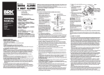
Diagram 1
BLUE (NEUTRAL)
When selecting cable for connecting interlinked
smoke alarms the interlink wire should be
BLACK or GREY (INTERLINK)
treated as live.
EARTH
2. Use either of the methods of installation
shown in diagrams1 and 2.
The installation method shown in diagram 1 is
JUNCTION BOX
suitable for a plasterboard or similar ceiling
where access to the void behind it is available
and suitable to mount the junction box.
The installation method shown in diagram 2 is
BASEPLATE
suitable for concrete or similar ceilings where
BROWN
WHITE
access is insufficient or where surface wiring
BLUE
is necessary.
3. Connect the brown wire to the brown (live)
ALARM
in the house wiring and the blue wire to the
blue (neutral). NO CONNECTION SHOULD
BATTERY
BE MADE TO THE MAINS ELECTRICITY
ACCESS
DOOR
SUPPLY EARTH TERMINAL. TERMINATE
HOUSE WIRING EARTH
IN SPARE CONNECTOR.
4. For multiple alarm installations use a “three
core and earth” style cable between all the
INSTALLATION USING JUNCTION BOX
alarms to be interconnected and connect
the third core of that cable to the white wire from the smoke alarm. DO NOT use the earth wire
for the interconnect line. This must be treated as live, i.e. insulated and sheathed. If the alarm
is not going to be interconnected, cap the unused wires.
5. Remove the baseplate from the back of the alarm by twisting anti-clockwise as far as it will go.
(about 12 mm). Detach the locking pin.
650MBX, 670MBX and 680MBX
EARTH
Detach battery door screw from the base plate. Diagram 2
BLUE (NEUTRAL)
BLACK or GREY (INTERLINK)
Open the battery door on the back of the alarm,
BROWN (LIVE)
connect the battery, close the door and secure
with the screw provided before fitting the alarm
PATTRESS
to the baseplate.
Test the alarm using the test button.
6. Attach the flat side of the mounting plate and
tighten screws to fit snugly against the pattress
or junction box and ceiling or wall.
7. Bring the power connector through the centre
opening of the plate.
IMPORTANT: THE PAPER GASKET SUPPLIED MUST
BE FITTED BETWEEN THE REAR OF THE ALARM
AND THE MOUNTING PLATE TO PREVENT THE
ALARM FROM BECOMING CONTAMINATED BY
DUST AND TO ENSURE THE CORRECT OPERATION
BASEPLATE
OF THE ALARM. Gasket not required on alarms fitted
WHITE
BROWN
with protective film on the back.
BLUE
8. Plug the lead into the rear of the alarm.
9. Place the alarm on the baseplate by lining up
ALARM
arrows on the baseplate and the alarm rim and
twist clockwise to fasten.
BATTERY
ACCESS
To secure the alarm to the baseplate, insert the
DOOR
locking pin (removed from the base in 5 above)
into the ‘T’ shaped slot located above the arrow
on the rim of the alarm.
370MBX
Open the battery drawer, insert the battery
contacts first according to the markings on the inside of the drawer front, close the drawer
and test the alarm using the test button before turning on the mains electricity supply.
Fit either locking key into the ‘Key Slot’ above the battery drawer handle. Key number 1 locks
the alarm to the base, key number 2 locks the alarm to the baseplate AND the battery drawer
closed. These keys remain in place and should only be removed when opening the battery
drawer or removing the alarm from the baseplate.
LOCKING PINS / KEYS MUST BE FITTED. DO NOT ATTEMPT TO REMOVE THE ALARM FROM
THE BASEPLATE WITHOUT FIRST REMOVING THEM.
10. Switch on the mains electricity supply.
11. Check that the green light is on and that the red light is flashing every 45 seconds or so.
The lights are located behind the grille on the front of the alarm.
12. Press and hold the test button until the alarm sounds. NOTE: On the 670 series, pressing this
button places the alarm in pause mode.
SYSTEMS OF MORE THAN ONE ALARM
Test each alarm in the system checking that all other alarms in the system are triggered within 10
seconds.
WARNING
Do not attempt to test the alarm with flame heat or smoke, the results may be misleading and
may damage the alarm.
The dust cover must be removed as late as possible before commissioning. This will reduce the
chances of the alarm being contaminated by building dust etc.
Remove the alarm from the system before testing the wiring with high voltage insulation testing
equipment otherwise this will damage the alarm and will invalidate the warranty.
C: WHERE TO LOCATE
1. As a minimum smoke alarms should be located between sleeping areas and potential sources
of fire such as living rooms and kitchens. In single storey homes with one sleeping area a
smoke alarm should be installed in the hallway as close as possible to the living
accommodation. To ensure audibility in the bedrooms it may be necessary to install more than
one smoke alarm, particularly if the hallway is more than 15m long. In single storey homes
with two separate sleeping areas, a minimum of two smoke alarms is required, one outside
each sleeping area. In multilevel or split level homes as a minimum a smoke alarm should be
installed on the ground floor between the staircase and any rooms in which a fire might start
and on each storey in circulation areas which form part of the escape route (normally hallways
and landings).
NOTE: Heat alarms should not be used in escape routes instead of smoke alarms. They should
only be used in the applications listed below in addition to smoke alarms and should always be
interconnected to smoke alarms.
2. Additional alarms should be installed in bedrooms in anticipation of fires originating there,
caused by faulty wiring, lights, appliances, smokers or other hazards.
3. For best protection, smoke alarms should be installed in every room in your home, apart from
those listed in the ‘LOCATIONS TO AVOID’ section. Heat alarms should be used in kitchens,
boiler rooms, laundry rooms, garages and such like where smoke alarms would be unsuitable.
All alarms must be interconnected.
4. Install smoke alarms in circulation areas at a distance no greater than 7.5m from the farthest
wall, no greater than 7.5m from a door to any room in which a fire might start, no greater than
7.5m from the next smoke alarm and no greater than 3m from bed.
5. When heat alarms are installed in a room, they should be at a distance no greater than 5.3m
from the farthest wall no greater that 5.3m from a door to any room in which a fire might start
and no greater than 5.3m from the next heat or smoke alarm.
6. As it is Impossible to predict the source of a fire the best location for an alarm is the centre of
the room or hallway. If it is necessary to locate the smoke alarm on a wall always locate the
detection element of the alarm 150mm to 300mm (6 to 12 inches) below the ceiling and the
bottom of the alarm above the level of doors and other openings.
NOTE: Heat alarms should not be wall mounted.
7. In rooms with simple sloped, peaked or gabled ceilings install smoke alarms 900mm (3 feet)
from the highest point of the ceiling. ‘Dead air’ at the peak of the ceiling may prevent smoke
from reaching the alarm in time to provide an early warning.
8. Closed doors and other obstructions will interfere with the path of smoke and heat to an alarm
and may prevent occupants from hearing an alarm on the other side of a closed door. Install
sufficient alarms to compensate for closed doors and other obstacles.
9. Your local fire brigade or insurance company may be able to give you further advice. Call them
and ask. Further help and information may also be found in BS5839 Part 6 and the Fire Safety
guidance given by the Department of Transport, Local Government and the Regions (DTLR).
CAUTION: Research indicates that substantial increases in warning time can be obtained with
each properly installed additional alarm, It is strongly recommended that the advice above be
followed to ensure maximum protection.
IMPORTANT: These smoke and heat alarms are intended primarily for use in single-family
occupancy private dwellings. For use in other applications the manufacturers advice should be
sought.
LOCATIONS TO AVOID
DO NOT locate alarms: 1. In turbulent air from fans, heaters, doors, windows, etc.
2. In high humidity areas such as bathrooms and shower rooms or where the temperature
exceeds 39ºC (100ºF) or falls below 5ºC (40ºF)
3. At the peak of an ‘A’ frame ceiling – dead air at the top may prevent smoke and heat from
reaching the alarm to provide an early warning.
4. Less than 300mm (12 inches) from a wall when mounted on the ceiling.
5. In insect infested areas. Tiny insects may affect performance.
6. (Smoke alarms) in poorly ventilated kitchen or garage. Combustion particles from cooking or
car exhaust could trigger a nuisance alarm
7. In very dusty or dirty areas – dirt and excessive dust can impair the performance of the alarm.
8. Within 300mm (12 inches) of a light fitting or room corners.
9. In locations that would make routine testing or maintenance hazardous. (e.g. over a stairwell).
10. On poorly insulated walls or ceilings.
11. Near objects such as ceiling decorations that might impede the path of smoke or heat to the
alarm.
12. Within 1500mm (5 feet) of a fluorescent light fitting and keep wiring at least 1000mm (39
inches) from these fittings. Do not install alarms on circuits containing fluorescent light
fittings or dimmer switches.
Further help and information may be found in BS5839 Part 6
D: USER INFORMATION
Features
• Operating Lights – A continuous green light indicates the alarm is receiving mains power. The
red light doubles as an alarm source indicator and flashes approximately every 45 seconds to
confirm circuitry integrity.
• Alarm Source Indicator – Red light will flash every second in the unit originating the alarm. Red
lights on other alarms flash every 45 seconds.
• Alarm Pause (670 range only) – Silence your smoke alarm by momentarily pressing the test
button. Ideal when non-emergency smoke (e.g. cooking fumes) cause nuisance alarms. Red
light flashes every ten seconds to remind you that the alarm has been silenced. Double beep
indicates that the alarm has automatically reset after approximately 10 minutes.
• The 370MBX has a separate alarm pause button. The alarm beeps every 45 seconds for 10
minutes when in pause.
Be Prepared
Smoke and heat alarms properly installed and maintained are an essential part of a good home fire
safety programme. Review fire hazards and eliminate dangerous conditions wherever possible.
When fire strikes a prepared and practiced escape plan could prove vital. Your local fire brigade
may be willing to advise you. Call them and ask. Consider and discuss the following safety hints:
• Ensure everyone is familiarized with the alarm signal.
• Always test doors with your hands before flinging them open. If they feel warm, fire may be
walled up behind them – leave closed and find another escape route.
• Don’t waste time collecting possessions. Rouse all occupants and leave the building; your life is
more valuable.
• GET OUT, STAY OUT, GET THE FIRE BRIGADE OUT!
• Keep everyone in a set meeting place after your escape.
• If trapped inside, stay close to the floor, cover your mouth with cloth and conserve breath while
you crawl to safety.
• Keep all windows and doors closed except for escape purposes.
• Prepare and practice an escape plan before a fire starts.
Draw a floor plan. Have fire drills often. Practise your escape.
Simple Maintenance
Vacuum every six months to keep unit working efficiently by firstly turning off the mains electricity
supply and vacuuming through the vents using a soft brush attachment. Keep the nozzle from
touching the unit. SWITCH POWER BACK ON WHEN YOU HAVE FINISHED.
Test the alarm once a week by: • Checking that the green light is on and that the red light is flashing every 45 seconds or so. The
lights are located behind the grille on the front of the alarm.
• Press and hold the test button until the alarm sounds. NOTE: Pressing this button on alarms in
the 670 series also places the alarm in pause mode.
MBX MODELS.
Change the battery with a new one when the alarm beeps every 45 seconds.
370MBX Models Only.
Turn off the mains electricity supply. Remove the locking pin by inserting a small screwdriver into
the square hole at the top of the battery drawer. Apply pressure at the tip of the screwdriver,
pushing it up onto the locking pin. The pin will pop out.
Open the battery drawer and remove the old battery, insert the new battery contacts first according
to the markings on the inside of the drawer front, close the drawer and test the alarm using the test
button. Refit the locking pin and then turn on the mains electricity supply. NOTE: The battery
drawer cannot be closed if the battery is missing.
All other MBX Models (Excluding 10 year Lithium versions.)
Turn off the mains electricity supply, remove locking key, rotate the alarm approximately 10mm
anti-clockwise and remove the alarm from the ceiling. Unplug the alarm from the mains supply.
Remove the screw and prise open the battery compartment door on the back of the alarm to
replace the battery with one of the following: Duracell MN1604, MX1604, Eveready PP3B PP3S,
6LF22 Gold Peak 1604A, 1604S. Close the battery door refit the screw and re-assemble the alarm
to the ceiling ensuring that the mains plug is securely fitted. Test the alarm using the test button
then turn on the mains electricity supply. PLEASE NOTE: The alarm cannot be fitted to the
baseplate without a battery installed.
650MBX-10, 670MBX-10 and 680MBX-10
A 9 volt lithium battery is fitted to these alarms. Replace with Ultralife U9VL batteries.
650MRL, 670MRL, 680MRL
Rechargeable Lithium batteries provide approximately 6 months back up power supply in the event of
a mains supply failure. The alarm may beep every 45 seconds for a few hours after a mains supply
failure while the batteries re-charge.
650MC, 670MC, 680MC.
High performance capacitors provide a back up power supply for a minimum of 72 hours (4 minutes
of alarm), in the event of a mains supply failure. The alarm may beep every 45 seconds for a few
hours after a mains supply failure while the capacitors re-charge.
Troubleshooting
Problems are indicated by four events: 1. Alarm does not sound upon pressing the test button
2. Green light does not illuminate when mains power is on.
3. Red operating light remains steadily on, or off (i.e. does not flash every 45 seconds when alarm is
in standby).
4. Alarm emits a beep every 45 seconds when back up power supply should be fully charged.
Try the following: 1. Inspect the fuse in the power circuit to the alarm
2. Gently vacuum as detailed in ‘Simple Maintenance’.
3. For MBX models only, replace the battery.
4. Call a qualified electrician to inspect the house wiring and connections to the alarm.
If these procedures do not eliminate the problem. DO NOT ATTEMPT REPAIRS. In the first instance
contact the manufacturer for further advice.
If the alarm is still within warranty period and terms, return the unit with proof of purchase to the
distributor, indicating the nature of the problem. Units beyond warranty cannot be economically
repaired. For address see the bottom of this page.
False Alarms
Abnormal air conditions may cause the highly sensitive alarm to give a ‘false’ alarm. DO NOT
DISCONNECT THE ALARM. If no fire is apparent, ventilate the room and/or operate the alarm pause (If
fitted).
WARNING: IF THERE IS ANY QUESTION AS TO THE CAUSE OF AN ALARM, ALWAYS ASSUME THAT
IT IS DUE TO AN ACTUAL FIRE AND FOLLOW YOU FIRE EMERGENCY PLANS. Do not assume the
alarm is a nuisance alarm and activate alarm pause (if fitted).
Dust can have an adverse effect. Vacuum as recommended above.
Do not paint the unit.
Other factors such as nicotine contamination may also adversely affect the alarm.
Radioactive Contents
Ionization type smoke alarms utilise a tiny amount of radioactive material, 0.9 microcuries (30
kilobequerels) of Americium 241, to detect smoke. This material is in the form of a sealed source and
represents no hazard whatsoever to anyone installing or using the smoke alarm. Any stray particles
would be unable to “penetrate the dead layer of skin and thus do not constitute an external hazard”.
(Radiation Protection Guidance for Scientists and Physicians). All Dicon ionization smoke alarms have
been rigorously tested by the National Radiological Protection Board to ensure absolute safety.
Disposal of Ionization type Smoke Alarms 370MBX, 670M, 670MC, 670MRL, 670MRB, 670MBX
As a responsible company, Dicon Safety Products is constantly monitoring and updating its systems
and procedures to anticipate changes in safety and environmental legislation worldwide. For instance,
changes in European legislation will soon have an impact on the disposal of some smoke alarms.
For the latest information on the disposal of smoke alarms, please contact our customer helpline on
+44 1452-712459.
Guarantee
Your Dicon Alarm, excluding the battery in MBX models, is warrantied for five years from the date of
purchase against defects in materials and workmanship. Units returned to Dicon with proof of
purchase during this period as a result of such defects will be repaired or replaced at Dicon’s option
without charge. This warranty only covers defects in material or workmanship in normal residential
use and does not cover damage resulting from negligent handling, misuse or lack or reasonable care.
YOUR ALARM IS NOT A SUBSTITUTE FOR PROPERTY, DISABILITY OR OTHER INSURANCE OF ANY
KIND. APPROPRIATE COVERAGE IS YOUR RESPONSIBILITY. CONSULT YOUR AGENT.
This warranty does not affect your statutory rights in any way.
In the event of a problem with your alarm or you have any questions concerning its use; care and
service please consult this manual.
If you require any further help or clarification please write to:
Dicon Safety Products (UK) Ltd, PO Box 402, Gloucester. GL2 9YB
or phone our Helpline on: 01452 712459
PLEASE KEEP THIS MANUAL IN A SAFE PLACE
Please note that specifications may be subject to change.