1
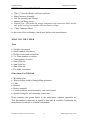
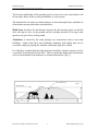
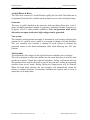
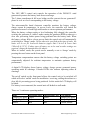
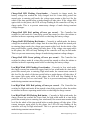
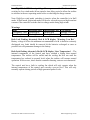
Rutland FM1803-2 Furlmatic
Windcharger
Owners Manual
Document No: SM-146 Issue D 14.03.08
Rutland FM1803-2
Document No: SM-146 Issue D 14.03.08
Installation & Operation
1
Marlec Engineering Co Ltd
Rutland FM1803-2
Installation & Operation
CONTENTS
Page
INTRODUCTION................................................................................ 3
CHECK YOU HAVE RECEIVED....................................................... 4
WHAT YOU WILL NEED, TOOLS, OTHER..................................... 4
SITING THE WINDCHARGER.......................................................... 5
SYSTEM DESCRIPTION & PRINCIPLE OF OPERATION………. 6
Aerofoil Blades
Generator
Tail Assembly
Control Unit
MOUNTING TOWER ………….……………………………………. 10
ASSEMBLY & INSTALLATION........................................................ 12
Blade & Hub Assembly.......................................... 12
Tail Assembly……………………………………. 14
Tower Preparation..............................……………. 15
Control Unit Installation………………………….. 16
BATTERIES.....................................................................................… 17
CABLE SPECIFICATION................................................................... 18
ELECTRICAL CONNECTION........................................................... 19
FITTING GENERATOR TO THE TOWER………………………… 20
Final Mechanical check…………………………. 20
UP AND RUNNING...........................................................................
21
SPECIFICATION AND PERFORMANCE......................................... 22
INSPECTION AND MAINTENANCE............................................... 23
TROUBLESHOOTING....................................................................... 24
Document No: SM-146 Issue D 14.03.08
2
Marlec Engineering Co Ltd
Rutland FM1803-2
Installation & Operation
INTRODUCTION
This manual contains important information concerning your Rutland FM1803
Series 2 Windcharger system and its installation and operational characteristics.
It is strongly recommended that you read this manual and familiarise yourself with
its contents before installing and operating the Windcharger system.
The Rutland FM1803 Series 2 Windcharger is designed to provide a direct current
(DC) power supply via a battery bank for low voltage equipment, lighting,
inverters etc. in domestic and professional applications.
WARNING!
• When turning, the Windcharger is capable of generating voltages in excess of
the nominal voltage Caution must be exercised at all times to avoid electric
shock.
• Never disconnect the batteries from the controller when the turbine is running.
• The wind generator must never be operated on open circuit, (ie without control
unit connected, since hazardous voltages can be generated.
• No attempt to work on the system should be made until the wind generator is
restrained from turning.
• The Windcharger is fitted with ceramic magnets which can be damaged by
heavy handling. The main generator assembly should be treated with care
during transit and assembly.
• It is essential to observe the correct polarity when connecting the Windcharger
and all other components into an electrical circuit. Reverse connection will
damage the Windcharger system and invalidate the warranty.
.
• Do not adjust the settings on the control unit without reference to the
manufacturer.
• If in doubt, refer to your dealer, a competent electrical engineer or the
manufacturer.
Document No: SM-146 Issue D 14.03.08
3
Marlec Engineering Co Ltd
Rutland FM1803-2
Installation & Operation
CHECK YOU HAVE RECEIVED
•
•
•
•
•
Three (3) Aerofoil Blades and 9 nuts and bolts
Main Generator Assembly
Tail Fin assembly and Fixings
Spinner and fixing screws
Control Unit – Check that the voltage indicated on the connection label and the
side of the housing corresponds with your battery voltage.
• 3 Way Connector Block
In the event of loss or damage, consult your dealer or the manufacturer.
WHAT YOU WILL NEED
Tools
•
•
•
•
•
•
•
•
•
Suitable wire stripper
Small terminal screwdriver
Phillips (cross-head) screwdriver
2 x 13mm spanners or sockets
10mm spanner or socket
8mm Allen key
6mm Allen key
4mm Allen key
Flat blade screwdriver
Other Items You Will Need
•
•
•
•
•
•
•
Mounting tower
Winch or other suitable lifting/pulling equipment
Cable
Batteries
Battery terminals
Connector blocks (as determined by your total system)
Suitable fixings for wall mounting control unit.
Please complete the system details in the maintenance schedule (appendix A).
This information is important & should be kept safe & available if contacting the
manufacturer for advice or technical information.
Document No: SM-146 Issue D 14.03.08
4
Marlec Engineering Co Ltd
Rutland FM1803-2
Installation & Operation
SITING THE WINDCHARGER
The location and height of the mounting pole or tower for your wind turbine will
be the major factor in the overall performance of your system.
The smooth flow of wind over land and water is often interrupted by a multitude of
obstructions causing wind sheer and turbulence.
Wind sheer describes the interference between the fast moving upper air and the
slow moving air close to the ground and the resulting decrease in average wind
speed as one gets closer to the ground.
Turbulence is caused by the wind passing over obstructions such as trees and
buildings. Both wind sheer and turbulence diminish with height and can be
overcome simply by putting the machine sufficiently high above them.
It is therefore essential that the wind generator should be located in an area as free
as possible from disturbed wind flow. Bear in mind that downwind obstructions
can be as detrimental to performance as upwind obstructions (Fig.1).
AREA OF TURBULENCE
Fig.1
WIND DIRECTION
2H
H
2H
Document No: SM-146 Issue D 14.03.08
20H
5
Marlec Engineering Co Ltd
Rutland FM1803-2
Installation & Operation
SYSTEM DESCRIPTION & PRINCIPLE OF OPERATION
Aerofoil Blades & Rotor
The 1803 rotor consists of 3 aerofoil blades rigidly fixed to a hub. The blades are at
an optimum fixed pitch for variable speed operation over a wide wind speed range.
Generator
The rotor is rigidly attached to the generator shaft providing direct drive to the 3
phase brushless permanent magnet ac generator, producing variable frequency ac
at approx 120v L-L under normal conditions. Note: the generator must not be
allowed to run open circuit since high voltages can be generated.
Yaw system
The complete wind generator assembly is mounted on yaw bearings allowing free
rotation on it’s vertical axis to enable it to respond to changes in wind direction.
The yaw assembly also includes a slipring & brush system to transmit the
generated current to the fixed transmission cable while allowing free 360° yaw
rotation.
Tail assembly
The inclined tail fin is hinged to the rigid tail boom on durable sleeve bearings.
The tail is designed to direct the turbine into the main direction of wind at wind
speeds up to approx 35mph, above this the automatic ‘furling’ mechanism will turn
the generator at an angle to the wind to protect the generator, turbine & supporting
structure from severe winds. During furling the output power will be reduced.
When the high wind subsides, the tail assembly will automatically return the
turbine to normal operation. In turbulent conditions the system may be seen to
repeat this cycle many times.
Document No: SM-146 Issue D 14.03.08
6
Marlec Engineering Co Ltd
Rutland FM1803-2
Installation & Operation
Control Unit
The 1803 MPC1 control unit controls the operation of the FM1803-2 wind
generator & protects the battery bank from overcharge.
The 3 phase transformer & full wave bridge rectifier convert the raw generated 3
phase ac to dc at a level corresponding to the battery voltage.
The microcontroller based electronic controller monitors the battery voltage,
charge current & temperature. At pre-set levels, the controller will switch the
generator between Low and High wind modes to ensure optimum performance.
When the battery voltage reaches a level indicating fully charged, the controller
switches the generator to ‘stalled’ mode causing the generator RPM to reduce to a
slow idle, preventing further power being generated into the battery bank. When
the battery voltage falls to a lower pre-set limit, the control unit will automatically
switch back to ‘charge’ mode. Unless otherwise specified at the time of order, the
limits will be set for lead acid batteries (upper limit 2.4v/cell & lower limit
2.08v/cell @ 25°C). If other types of battery are to be used or other settings are
required, contact the manufacturer for advice.
When in ‘stalled’ mode, the system can be manually re-set to ‘charge’ mode by
pressing the reset button on the front panel.
Temperature compensation ensures that the battery voltage switching points are
automatically adjusted for ambient temperature to maintain optimum battery
performance.
A digital LCD display shows battery voltage, charge current, generated power,
operating mode & warnings. Coloured LEDs also indicate operating status &
warnings.
The on/off switch on the front panel allows the control unit to be switched off
which will select ‘stalled’ mode for installation / servicing, stalling the turbine to a
slow idle & preventing power being produced. In this mode the LCD display will
be blank.
If a battery is not connected, the control unit will default to stall mode.
There are 3 continuous operating modes:
Mode
Low/High LED
Charge Low Wind Green
Charge High Wind Red
Stalled
Red
Document No: SM-146 Issue D 14.03.08
Charge/Stall LED
Green
Green
Red
7
LCD Display
Charge Low Wind
Charge High Wind
Turbine Stalled
Marlec Engineering Co Ltd
Rutland FM1803-2
Installation & Operation
Transitional modes indicated by LEDs:
Charge/Stall LED Flashing Green/Amber – Currently in charge mode, the
battery voltage has reached the fully charged level & a time delay period has
started prior to entering stall mode, the voltage must remain at this level for the
whole of the time period before a mode change will take place. If the voltage falls
again while in this phase, the LED will stop flashing & the controller will stay in
charge mode. This is to prevent unnecessary change of mode during transient
voltage changes.
Charge/Stall LED Red/ pulsing off once per second – The Controller has
switched to stall mode & a time delay period has started to allow the turbine to
stabilize in the new operating mode before re-checking the battery voltage.
Charge/Stall LED Flashing Red/Amber – Currently in stalled mode, the battery
voltage has reached the lower voltage limit & a time delay period has started prior
to entering charge mode, the voltage must remain at this level for the whole of the
time period before a mode change will take place. If the voltage rises again while
in this phase, the LED will stop flashing & the controller will stay in stall mode.
This is to prevent unnecessary change of mode during transient voltage changes.
Charge/Stall LED Green/ pulsing off once per second – The Controller has
switched to charge mode & a time delay period has started to allow the turbine to
stabilize in the new operating mode before re-checking the battery voltage.
Low/High Wind LED Flashing Green/Amber – Currently in Low wind mode,
the charge current has reached the upper limit for low wind mode & a time delay
period has started prior to entering High wind mode, the current must remain at
this level for the whole of the time period before a mode change will take place. If
the current falls again while in this phase, the LED will stop flashing & the
controller will stay in Low wind mode. This is to prevent unnecessary change of
mode during transient current changes.
Low/High Wind LED Red/ pulsing off once per second – The Controller has
switched to High wind mode & has started a time delay period to allow the turbine
to stabilize in the new operating mode before re-checking the charge current.
Low/High Wind LED Flashing Red/Amber – Currently in High wind mode, the
charge current has reached the lower limit for high wind mode & a time delay
period has started prior to entering Low wind mode, the current must remain at this
level for the whole of the time period before a mode change will take place. If the
current increases again while in this phase, the LED will stop flashing & the
controller will stay in High wind mode. This is to prevent unnecessary change of
mode during transient current changes.
Document No: SM-146 Issue D 14.03.08
8
Marlec Engineering Co Ltd
Rutland FM1803-2
Installation & Operation
Low/High Wind LED Green/ pulsing off once per second – The Controller has
switched to Low wind mode & has started a time delay period to allow the turbine
to stabilize in the new operating mode before re-checking the charge current.
Note: High/Low wind mode switching is inactive when the controller is in Stall
mode. In Stall mode, high wind mode will also be selected to prevent high transient
currents if the controller switches back to charge mode during high winds.
Warnings
Mode
Low Battery Volts
Over Temperature
Low/High LED
Flashing Red
Flashing Red
Charge/Stall LED LCD Display
Flashing Red
Warning: Low Bat
Flashing Red
Over Temperature
Both Leds flashing alternately Red & LCD display ‘Warning: Low Bat’ –
Battery voltage is below the minimum recommended level & is therefore seriously
discharged, any loads should be removed & the batteries recharged as soon as
possible to avoid permanent damage to the battery.
Both Leds flashing alternately Red & LCD display ‘Over Temperature’ – The
internal components of the control unit have reached a higher than normal
temperature. The turbine will be stalled and the cooling fan will run until the
temperature has reduced to normal levels when the turbine will resume normal
operation. If this occurs, check that the controller housing vents are not obstructed.
The control unit has a built in cooling fan which will only operate when the
internal temperature of the control unit exceeds a pre-set level. This will only
normally operate during periods of high generated power levels.
Document No: SM-146 Issue D 14.03.08
9
Marlec Engineering Co Ltd
Rutland FM1803-2
Installation & Operation
MOUNTING TOWER
The Rutland 1803-2 is designed to fit inside a round tube with an internal diameter
of 81mm.
A suitable mounting pole can be erected using 80mm (3“) galvanised (medium)
tube to BS1387 a minimum height of 6.5m, 10m or greater is recommended. The
tube must be supported by a minimum of 2 sets of four guy lines.
The attachment points for the guy lines to the tower should be securely fixed to the
tower.
• All items should be galvanised or stainless steel for protection against corrosion.
• Where guy lines are looped, the loop must incorporate a thimble and be fitted
with a minimum of three rope grips.
• All ground fixings must be made suitable according to the ground conditions.
Pivot type towers are recommended as these allow for easier installation and
lowering for access to the wind generator for maintenance. A form of pivoting
tower is suggested in Fig 2. Non-guyed pivoting towers are available, for further
tower details contact the dealer or manufacturer.
Document No: SM-146 Issue D 14.03.08
10
Marlec Engineering Co Ltd
Rutland FM1803-2
Installation & Operation
R4400
1300
2600
2600
Fig 2. Typical Tower
Document No: SM-146 Issue D 14.03.08
11
Marlec Engineering Co Ltd
Rutland FM1803-2
Installation & Operation
ASSEMBLY AND INSTALLATION OF THE WINDCHARGER
Blade & Hub Assembly
The blade hub rear assy complete with blade bolts is pre-fitted to the
generator shaft, this must not be removed to fit the turbine blades.
Turbine Blade
Flat Side of
Blade
M8
washers
Hub Rear Assy
with protruding
blade bolts
M8 Nylock
Nuts
Hub Front Plate
‘D’ washer
Tab washer
Spinner fixing
boss
M10 x 25
Fig 3. Blade Hub Assembly
Document No: SM-146 Issue D 14.03.08
12
Marlec Engineering Co Ltd
Rutland FM1803-2
Installation & Operation
Blade & Hub Assembly continued
Fit the 3 turbine blades to the protruding blade bolts, ensuring the flat surface of
the blades faces the front plate.
Fit the front hub plate to the shaft with the pre-fitted pins protruding outwards.
Ensure alignment with the flats on the shaft, the pins with the holes in the hub
boss, and the cutouts with the spinner fixing holes in the blades.
Fit the nuts & washers to the blade bolts & tighten using 2 x 13mm spanners. If
necessary use a flat blade screwdriver from the back of the hub assembly to push
the bolts through.
Using a suitable hammer, drive the 3 protruding pins into the corresponding holes
in the front plate & boss assy, until the pins are flush with the front plate.
Fit the centre screw, ‘D’ washer & tab washer to the assembly & tighten the screw
securely to push the assembly back against the shoulder on the shaft. Ensure there
is no gap between the rear hub plate & shaft shoulder.
Using a hammer & suitable drift, bend the edges of the tab washer against the flats
on the centre screw to prevent loosening.
Check tightness of all screws. (Do not over-tighten).
Fit the plastic spinner in position on the front of the generator hub and secure in
place with the 3 No10 x 9.5 screws provided.
Alternatively the turbine and spinner can be fitted after mounting the generator
assembly to the tower.
Insert tab washer into
slot in front hub plate
Bend a corner of the tab
washer against a flat on the
bolt head
Fig 4. Turbine Assembly Fixing
Document No: SM-146 Issue D 14.03.08
13
Marlec Engineering Co Ltd
Rutland FM1803-2
Installation & Operation
Tail Assembly
Insert the tail assembly into the end of the tail boom, aligning the threaded holes in
the tail mounting with the clearance holes in the tail boom. Insert the two M10 x
16 Button Cap Screws & Shakeproof washers & tighten to a torque of 20Nm.
When fitted, the tail fin will be inclined 15° to the vertical.
Tail Assembly
M10 Button Cap
Screws & Shakeproof
washers
Tail Boom
Fig 5. Tail Assembly
Document No: SM-146 Issue D 14.03.08
14
Marlec Engineering Co Ltd
Rutland FM1803-2
Installation & Operation
Tower Preparation
• The post adaptor fitted to the 1803-2 is designed to fit inside a standard 81mm
(3”) internal diameter tube. The adaptor is provided with a flat on one side to
clear the weld seam on seamed pipe.
• Mark and centre-punch four positions diametrically opposite, at 45° to the pipe
seam if necessary, 20mm from the top of the tube.
• Drill four holes 12.5mm in diameter on centre-punch positions & remove burrs.
Post Adaptor
M12 x 25 Button Cap Screws
& Shakeproof Washers
20
Top of Tower
Pipe Seam
Fig 6. Tower Preparation
Document No: SM-146 Issue D 14.03.08
15
Marlec Engineering Co Ltd
Rutland FM1803-2
Installation & Operation
Control Unit Installation
The Control unit should be installed as close as possible to the batteries to
minimise the length of the main battery leads, at the same time the unit should be
protected from battery fumes from vented batteries.
Ensure adequate ventilation is provided to allow efficient heat dissipation via the
control unit vents. These vents must not be covered or obstructed.
The unit is not weatherproof & therefore must be suitably protected.
Mount the unit securely to a wall or other vertical surface, using the mounting
holes provided (hole centres are 270mm W x 200mm H), in a suitable location
allowing for cable entries in the base of the unit. The cable entries are fitted with
blanking grommets which need to be pierced or can be removed for attachment of
20mm conduit fittings if required.
Vents
Front Panel
fixing screws
On / Off
Switch
Mounting
Holes
LED
Indicators
Vents
Mounting
Holes
Manual Re-set
Push button
Front Panel
fixing screws
Fig 7. Control Unit
Document No: SM-146 Issue D 14.03.08
16
Marlec Engineering Co Ltd
Rutland FM1803-2
Installation & Operation
BATTERIES
Total = 12v
400Ah
4800Wh
Fig.8
Fig.9
Total = 24v
200Ah
4800Wh
12v
200Ah
12v
200Ah
12v
200Ah
12v
200Ah
Leisure/Deep Cycle batteries are specifically designed for good performance in
terms of charge/discharge cycles. Batteries are the most important part of your
battery charging system and should be sized according to your load requirements
and provide at least 3 days reserve capacity. This will reduce cycling, prolong the
life of the battery and ensure system reliability during periods of low wind. If in
doubt about battery sizing, contact your dealer or the manufacturer.
The minimum battery capacity recommended is 400Ah @ 12v, 200Ah @ 24v
Permanent connections should always be made to the battery terminals. Never use
crocodile clips or similar devices. Battery terminals should be well greased with
petroleum jelly or similar.
Batteries may be linked as follows:
• In parallel to increase amp hours (Fig.8).
• In series to increase voltage (Fig.9).
• A combination of series & parallel to achieve desired voltage & capacity.
Only batteries of similar type & capacity & ideally the same manufacturer should
be connected together in series or parallel.
Ensure the voltage indicated on your controller corresponds with your battery
voltage.
Document No: SM-146 Issue D 14.03.08
17
Marlec Engineering Co Ltd
Rutland FM1803-2
Installation & Operation
CABLE SPECIFICATION
The cable size used for connection of the Windcharger to the control unit should be
in accordance with table 1 in order to minimise voltage drop and ensure optimum
performance. 3 cores will be required.
Cable Run
(m)
Up to 50
Up to 100
Up to 150
Up to 250
Up to 450
Up to 700
Up to 1000
Minimum Cable Size
(mm²)
AWG
1.5
16
2.5
14
4
12
6
10
10
8
16
6
25
4
Table.1
The cable size for connection of the control unit to the batteries should be 10mm²
minimum; the use of smaller cables than recommended will reduce the
performance of the charging system.
The type of cable is dependent on the type of installation & national or local wiring
regulations. All cables must be suitably protected from mechanical damage.
All cables & installation should be in accordance with IEE Wiring regulations
The 3 phase cable from the WG is coloured in accordance with amendment 2 to
BS7671: 2001 (IEE wiring Regulations 16th Edition).
Phase 1- Brown
Phase 2 - Black
Phase 3 - Grey
Document No: SM-146 Issue D 14.03.08
18
Marlec Engineering Co Ltd
Rutland FM1803-2
Installation & Operation
ELECTRICAL CONNECTION
• Remove the four screws from the control unit front panel, carefully remove the
front panel by sliding upwards to release the latches into the main housing,
withdraw until the ribbon cable connecting the front panel to the main housing
can be accessed. Unplug the ribbon cable from the PCB in the main housing &
the front panel can then be removed.
• Using the cable selected (see Table 1), pass the cable through the inside of the
tower & route to the control unit. Leaving sufficient length of cable protruding
from the top of the tower to enable easy connection to the wind generator.
• Pass the cables through the grommet or conduit in the base of the control unit &
connect to the 3 terminals labelled for the wind generator. (The generator output
is 3 phase ac, therefore these connections can be made in any sequence).
• Using the cable selected for connection of the control unit to the batteries. Pass
the cables through the grommet or conduit in the base of the control unit &
connect to the 2 terminals labelled for the battery. It is vital to observe correct
polarity when connecting the battery cables otherwise serious damage will
result.
• Re-connect the ribbon cable & re-fit the control unit front panel. Move the
ON-OFF switch to the ‘OFF’ position.
Battery
Connections
Wind Generator
Connections
Voltage
Identification label
Fig 10. 12 & 24v Control Unit Connections
Document No: SM-146 Issue D 14.03.08
19
Marlec Engineering Co Ltd
Rutland FM1803-2
Installation & Operation
FITTING THE GENERATOR TO THE TOWER
• Connect the wind generator flying leads to the cable protruding from the tower
using the connector block supplied or other suitable connector. (The generator
output is 3 phase ac, therefore these connections can be made in any sequence).
Wrap the connection with insulation tape to secure/protect from the
environment. It is recommended that cable restraint is fitted to prevent the
weight of cable applying excessive load to the connections, a simple method of
achieving this is shown in Fig 11.
Cable From WG
Cable Tie
Connector Block
Cable to Controller
Fig 11. Cable strain relief
• Carefully locate the wind generator post adaptor into the top of the tower
ensuring the flat on the post adaptor aligns with the pipe seam if necessary.
• Push the adaptor into the tower while the cable is gently pulled from the tower
base to ensure it is not trapped, continue until the post adaptor is fully inserted
into the tower and the fixing holes align.
• Secure the wind generator to the tower using the four M12 x 25mm screws and
shakeproof washers provided. Tighten using an 8mm Allen key.
Final Mechanical Check
• Check the tightness of the blade screws and nose dome.
• Check the free rotation of the hub and yaw axis.
• Check for free movement of the tail fin.
Document No: SM-146 Issue D 14.03.08
20
Marlec Engineering Co Ltd
Rutland FM1803-2
Installation & Operation
UP AND RUNNING
• Before raising and securing the wind generator, check that:
1. All final mechanical checks have been made.
2. The cable is not trapped.
3. All electrical connections are secure and safe.
4. The switch on the control unit is in the “OFF” position.
• The wind generator can now be raised into position.
Take care to avoid all moving parts when raising and lowering the wind
generator.
• When raised, secure the structure firmly in an upright position. The
performance of your Windcharger can be impaired if the pole is not vertical.
• Connect the battery cables to the battery terminals using suitable permanent
connections. It is vital to observe correct polarity when connecting the
batteries otherwise serious damage will result.
• Move the switch on the control unit to the “on” position. If there is sufficient
wind the turbine should now accelerate and the LCD should display the
current operating conditions.
Document No: SM-146 Issue D 14.03.08
21
Marlec Engineering Co Ltd
Rutland FM1803-2
Installation & Operation
SPECIFICATION AND PERFORMANCE
The curve shown below is for ideal, non-turbulent wind conditions; this may not be achieved
in some installations.
70
35
60
30
50
25
40
20
30
15
20
10
10
5
0
CHARGE CURRENT INTO 24V
BATTERY (AMPS)
CHARGE CURRENT INTO 12V
BATTERY (AMPS)
CHARGE CURRENT v WINDSPEED
0
0
5
10
15
20
25
30
35
40
WINDSPEED (M/S)
Outline Dimensions (mm)
Tower Top Weight:
Controller Weight:
Shipping Dimensions:
1 pallet: 1200x675x520mm
35.32Kg
9.94Kg
Document No: SM-146 Issue D 14.03.08
22
74Kg
Marlec Engineering Co Ltd
Rutland FM1803-2
Installation & Operation
INSPECTION AND MAINTENANCE
To ensure long trouble free service from your 1803-2 wind generator, it is
important to determine a suitable inspection & maintenance schedule.
Maintenance intervals and requirements are specific to individual installations
& site conditions & therefore must be determined by the user during the first
year of service.
It is recommended that during the first year following installation that
inspections & necessary maintenance are carried out at 3, 6 & 12 months, the
results of which are used to determine future scheduled maintenance. A
maintenance schedule sheet is provided for convenience. It is recommended
that the maintenance schedule is completed & kept safe, & available if
contacting the manufacturer for advice or technical information.
From the findings of the 3, 6 & 12 months inspections, the user should
determine a suitable service interval.
• Before inspection, the turbine should either be lowered to the ground or
secured to prevent the generator from turning. To stop the generator from
turning proceed as follows:
Note: For safety reasons maintenance should not be attempted during
strong winds.
• Move the switch on the control unit to the “OFF” position. The turbine rpm
should reduce to a slow idle.
• Whilst the generator is in “stall” mode, it can be lowered to the ground or
blades restrained from turning.
Document No: SM-146 Issue D 14.03.08
23
Marlec Engineering Co Ltd
Rutland FM1803-2
Installation & Operation
TROUBLESHOOTING
In the unlikely event that your Rutland 1803-2 should develop a defect, the
turbine should either be lowered to the ground or secured to prevent the blades
from turning before the following inspection is carried out.
1. Read the ‘Electrical Connection’ and ‘Up and Running’ sections and be
satisfied that your system complies.
2. If your Rutland 1803-2 fails to turn, turns slowly or produces low output,
check the following:
• Is there sufficient wind? The Rutland 1803-2 needs 3m/s wind speed to
start charging. The wind speed across the turbine blades may be greatly
reduced in a built-up area compared with weather reports.
• Is the On/Off switch in the ‘ON’ position?
• Is the battery fully charged? Check the control unit LEDs, when the red
LED is lit it indicates that the battery is fully charged & the wind generator
will be in “stall” mode.
• Is a battery connected to the control unit? Check the control unit LEDs, if
no LED is lit this indicates no battery connection to the control unit & wind
generator will be in “stall” mode.
• Is the battery in good condition? Check the voltage and electrolyte level
of each battery.
• Check electrical continuity throughout the system, especially look for
corrosion and poor connections in cable joints and connector blocks.
• Check the brushes and slipring for wear or damage. To inspect the
brushes, remove the nacelle by removing the three fixing screws and slide
nacelle backwards towards the tail fin. The brushes and slipring can be
inspected. Remove any black deposits from slipring with emery paper.
• Check hub for free rotation with generator disconnected from control
unit. If the hub does not rotate freely, check for a possible short circuit in
the wiring. If no wiring fault is found refer to your dealer or manufacturer.
If in doubt, refer to your dealer or manufacturer.
Document No: SM-146 Issue D 14.03.08
24
Marlec Engineering Co Ltd
Rutland FM1803-2
Installation & Operation
FM1803-2 Maintenance Schedule (1st 12 months)
System Details
System Voltage
Generator Serial Number
Control Unit Serial Number
Remarks
Battery Capacity
Battery Type
Tower Height
Date of Installation
Check
Service Interval
Date
3 months
Remarks
Date
Blade Bolts
All other nuts & bolts
Turbine for smooth free rotation
Yaw axis for smooth free rotation
Tail hinge for smooth free rotation
General Condition
Tower assembly condition
Guy wire tension (if applicable)
Document No: SM-146 Issue D 14.03.08
Marlec
25 Engineering Co Ltd
6 months
Remarks
Date
12 months
Remarks
Rutland FM1803-2
Installation & Operation
FM1803-2 Maintenance Schedule
System Details
System Voltage
Generator Serial Number
Control Unit Serial Number
Remarks
Battery Capacity
Battery Type
Tower Height
Date of Installation
Check
Service Interval
Date
Remarks
Date
Blade Bolts
All other nuts & bolts
Turbine for smooth free rotation
Yaw axis for smooth free rotation
Tail hinge for smooth free rotation
General Condition
Tower assembly condition
Guy wire tension (if applicable)
Document No: SM-146 Issue D 14.03.08
Marlec
26 Engineering Co Ltd
Remarks
Date
Remarks
Rutland FM1803-2
Installation & Operation
LIMITED WARRANTY
The Marlec Engineering Company Limited Warranty provides free replacement cover
for all defects in parts and workmanship for 12 months from the date of purchase.
Marlec's obligation in this respect is limited to replacing parts which have been
promptly reported to the seller as having been in his opinion defective and are so found
by Marlec upon inspection.
Defective parts must be returned by prepaid post to Marlec Engineering Company
Limited, Rutland House, Trevithick Road, Corby, Northamptonshire, NN17 5XY,
England, or to an authorised Marlec agent.
This Warranty is void in the event of improper installation, owner neglect or natural
disasters and does not extend to support posts, inverters or batteries.
No responsibility is assumed for incidental or consequential damage, damage caused by
the use of any unauthorised components.
No responsibility is assumed for non "furling" versions of the Rutland Windcharger
(ie. the Standard and Marine generators) where Marlec or one of its authorised agents
finds that a generator incorporating a furling device should have been used.
Document No: SM-146 Issue D 14.03.08
27
Marlec Engineering Co Ltd