1
Operating Instructions
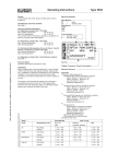
Design:
4-way solenoid valve, internally piloted, in the de-energized
condition port P connected to port B and port R connected to
port A. With manual override and flow restrictors.
Type 0420
Marking (example):
Body Material
PL
= Polyamide Plastic
Seal Materials and Fluids handled:
See Table1.
Fluid and Ambient Temperature:
For Hazardous Locations Div. 1 (T6 rated)
Max. Ambient Temperature
104 °F (40 °C)
Max. Fluid Temperature
140 °F (60 °C)
Seal Material
NBR = NBR
FKM = FKM
For Hazardous Locations Div. 2 and Ordinary Locations:
See Table1.
Pressure Range:
Minimum pressure differential between inlet and outlet port is
35 PSI.
Maximum inlet pressure see label on valve.
Circuit Function
G = 4-way
Installation:
Installation position as required. Ensure exhaust outlets for
pilot valve and main valve remain unrestricted but protect
against entry of dust, water and foreign matter. Pipework
should be clean. Do not put any loads on coil unit. Pipework
should be supported and installed to prevent strain on valve
body. Fittings should be sealed with PTFE tape, max. torque
80 in-lbs. Mounting is accomplished by means of two M4 selflocking threaded brass inserts located on the valve
underside. Maximum thread depth is 6 mm.
Table 1
Seal materials
Temperatures [°F]
Buna "N" (B)
FKM (F)
Air
Fluid T.
Ambient
+ 14 to + 122
+ 14 to + 122
+ 14 to + 122
+ 14 to + 122
Neutral
gas
Fluid T.
Ambient
+ 14 to + 122
+ 14 to + 122
+ 14 to + 122
+ 14 to + 122
Operating Instructions 0605/08_EU-EN_00893139
Fluid
Recorder No.
Voltage / Frequency / Power Consumption
Maximum Pressure
Approvals
The valve is either approved as
General Purpose valve for Hazardous Locations
Class I, Division 1, Group A, B, C, D
Class II, Division 1, Group E, F, G
Class III, Division 1 and 2
Operating Temperature T 4
or
General Purpose valve for Hazardous Locations
Class I, Division 1, Group A, B, C, D
Class II, Division 1, Group E, F, G
Class III, Division 1 and 2
Operating Temperature T 6
or
FM approved as
Nonincendive for Hazardous Locations
Class I, Division 2, Group A, B, C, D
Class II, Division 2, Group F, G
Class III, Division 1 and 2
Operating Temperature T 4A
UL listed for Ordinary locations
CSA approved for Ordinary locations
See label on the valve.
Operating Instructions
For this product to be considered UL-listed and CSA approved
for General Purpose and FM approved for Hazardous Locations
Division 2, it must be in conjunction with the type 2509 cable plug
connector (Electrically Operated Valves Parts, YSYI2).
The connector and gasket must be assembled to the valve with the
screw provided after the connection of the wire leads. This valve
and connector assembly is delivered together and is to be used as
one unit.
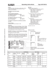
Wiring Diagram
Electrical Connection Type 2509
For valves to be used in Intrinsically Safe Applications the positive
pole is identified by a “+” on the pin or wire No. 1 has to be connected to the “+”.
See Control Drawing for the Rules of Interconnection.
Power*
Ground (green dot)
Warning:
All valves to be used in Intrinsically Safe Applications must be
clearly marked as Intrinsically Safe Apparatus.
Trouble-Shooting:
Check port connections, minimum operating pressure differential
if required and supply voltage. Ensure pilot hole in piston is clear
and pilot bore in the valve outlet is not abstracted. If core does not
pull in, check for short circuit, coil burn-out or foreign matter impeding core movement. A jammed or missing core causes the coil
to overheat in the case of AC supply.
Power*
* Orientation is not important
Electrical Connection:
Ensure supply voltage/frequency corresponds with that on label.
Voltage tolerance is ± 10 %.
Available Electrical Connections see “Marking”.
Wiring diagram see above.
Warning:
These products are designed to operate in a wide variety of applications, it is the user’s responsibility to select a model that is
appropriate for the application. This product is designed to be
installed only by suitably qualified and trained personnel.
Specifications should not be exceeded under any circumstances.
The torque for the terminal screw on type 2509 is 0,5 Nm
(4,4 lbf-in.).
Changes made to this product will render any applicable warranty
null and avoid.
Specifications subject to change without notice.
Any questions? Please call Bürkert Contromatic Technical Service
at (949) 223 31 00.
Germany
Contact address:
Bürkert Fluid Control Systems
Sales Center
Chr.-Bürkert-Str. 13-17
D-74653 Ingelfingen
Tel. + 49 (0) 7940 - 10 91 111
Fax + 49 (0) 7940 - 10 91 448
E-mail: [email protected]
International
Contact addresses can be found on the Internet at:
www.burkert.com
Bürkert
Company
Locations