1
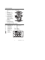
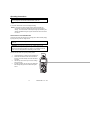
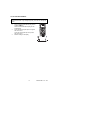
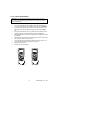
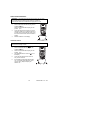
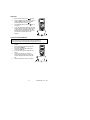
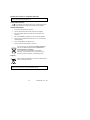
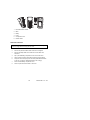
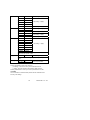
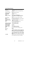
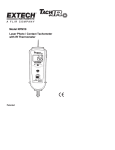
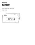
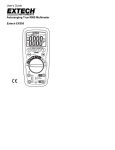
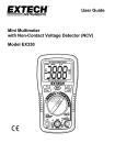
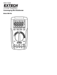
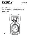
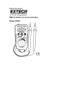
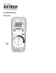
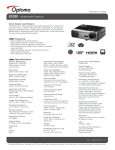
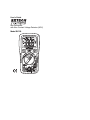
User's Guide
Mini Multimeter
with Non-Contact Voltage Detector (NCV)
Model EX330
Introduction
Congratulations on your purchase of the Extech EX330 Meter. The EX330 offers
AC/DC Voltage, AC/DC Current, Resistance, Diode, Continuity, non-contact
Voltage Detection, Capacitance, Frequency, Duty Cycle, and Temperature (Type
K) functions. Proper use and care of this meter will provide many years of reliable
service.
Safety
This symbol adjacent to another symbol, terminal or
operating device indicates that the operator must refer to
an explanation in the Operating Instructions to avoid
personal injury or damage to the meter.
WARNING
This WARNING symbol indicates a potentially hazardous
situation, which if not avoided, could result in death or
serious injury.
CAUTION
This CAUTION symbol indicates a potentially hazardous
situation, which if not avoided, may result damage to the
product.
MAX
600V
This symbol advises the user that the terminal(s) so
marked must not be connected to a circuit point at which
the voltage with respect to earth ground exceeds 600V.
This symbol adjacent to one or more terminals identifies
them as being associated with ranges that may, in normal
use, be subjected to particularly hazardous voltages. For
maximum safety, the meter and its test leads should not
be handled when these terminals are energized.
This symbol indicates that a device is protected
throughout by double insulation or reinforced insulation.
2
EX330-EU-ENG – V4.2 1/08
SAFETY INSTRUCTIONS
This meter has been designed for safe use, but must be operated with caution.
The rules listed below must be carefully followed for safe operation.
1.
NEVER apply voltage or current to the meter that exceeds the specified
maximum:
Input Protection Limits
Function
Maximum Input
V DC or V AC
600V AC and DC
mA AC/DC
500mA DC/AC
A AC/DC
10A DC/AC (for 30 seconds max.
every 15 minutes
Frequency, Resistance, Capacitance,
Duty Cycle, Diode Test, Continuity
250V DC/AC
Temperature
250V DC/AC
2.
3.
4.
5.
6.
7.
8.
USE EXTREME CAUTION when working with high voltages.
DO NOT measure voltage if the voltage on the "COM" input jack exceeds
600V above earth ground.
NEVER connect the meter leads across a voltage source while the function
switch is in the current, resistance, or diode mode. Doing so can damage
the meter.
ALWAYS discharge filter capacitors in power supplies and disconnect the
power when making resistance or diode tests.
ALWAYS turn off power and disconnect test leads before opening the
covers to replace the fuse or battery.
NEVER operate the meter unless the back cover and the battery and fuse
covers are in place and fastened securely.
If the equipment is used in a manner not specified by the manufacturer, the
protection provided by the equipment may be impaired.
3
EX330-EU-ENG – V4.2 1/08
Controls and Jacks
1.
2.
3.
4.
5.
6.
7.
8.
9.
10.
11.
12.
13.
AC Voltage Detector Sensor
AC Voltage Detector indicator
light
LCD
RELATIVE push-button
MODE button
Non-contact AC Voltage
Detector test button
Rotary function dial
10 ampere test lead jack
COM test lead jack
Test lead jack for voltage,
milli-amp, micro-amp,
resistance, capacitance,
frequency, and temperature
functions
RANGE button
HOLD button
Protective rubber holster
(must be removed to access
the rear battery compartment)
1
2
3
13
4
5
6
12
11
7
10
8
9
Display Symbols and Annunciators
n
m
k
M
Hz
%
AC
DC
ºF
•)))
nano (10-9) (capacitance)
milli (10-3) (volts, amps)
kilo (103) (ohms)
mega (106) (ohms)
Hertz (frequency)
Percent (duty ratio)
Alternating current
Direct current
Degrees Fahrenheit
Continuity
Diode test
µ
A
F
Ω
V
REL
AUTO
HOLD
ºC
micro (10-6) (amps, cap)
Amps
Farads (capacitance)
Ohms
Volts
Relative
Autoranging
Display hold
Degrees Centigrade
Battery status
5
EX330-EU-ENG – V4.2 1/08
Operating Instructions
WARNING: Risk of electrocution. High-voltage circuits, both AC and DC,
are very dangerous and should be measured with great care.
1. ALWAYS turn the function switch to the OFF position when the meter is not in
use.
2. Press the HOLD button to freeze a displayed reading
NOTE: On some low AC and DC voltage ranges, with the test leads not
connected to a device, the display may show a random, changing
reading. This is normal and is caused by the high-input sensitivity. The
reading will stabilize and give a proper measurement when connected
to a circuit.
NON-CONTACT AC VOLTAGE DETECTOR
The EX310 can detect the presence of AC voltage (from 100 to 600VAC) simply
by being held very near to a voltage source.
WARNING: Test the AC voltage detector on a known live circuit before
each use.
WARNING: Before using the meter in the AC Voltage Detector mode,
verify that the battery is fresh by confirming characters appear on the LCD
when the function dial is turned to any position. Do not attempt to use the
meter as an AC Voltage Detector if the battery is weak or bad.
The NCV function works on any rotary switch position.
1.
2.
3.
4.
Test the detector on a known live circuit before use.
Press and hold the NCV button for the duration of
the test. The meter will beep once when the button
is pushed.
Hold the top of the meter very close to the voltage
source as shown.
If voltage is present, the rim of the LCD display will
flash a bright orange and an audible warning will
sound.
6
EX330-EU-ENG – V4.2 1/08
AC VOLTAGE MEASUREMENTS
WARNING: Risk of Electrocution. The probe tips may not be long enough
to contact the live parts inside some 240V outlets for appliances because
the contacts are recessed deep in the outlets. As a result, the reading may
show 0 volts when the outlet actually has voltage on it. Make sure the
probe tips are touching the metal contacts inside the outlet before
assuming that no voltage is present.
CAUTION: Do not measure AC voltages if a motor on the circuit is being
switched ON or OFF. Large voltage surges may occur that can damage the
meter.
1.
2.
3.
4.
5.
6.
Set the function switch to the VAC position.
Insert the black test lead banana plug into
the negative COM jack.
Insert red test lead banana plug into the
positive V jack.
Touch the black test probe tip to the neutral
side of the circuit.
Touch the red test probe tip to the “hot” side
of circuit.
Read the voltage in the display.
If the measured AC voltage exceeds the
highest range of the meter (refer to the
specification table) an audible tone will
sound.
7
EX330-EU-ENG – V4.2 1/08
DC VOLTAGE MEASUREMENTS
CAUTION: Do not measure DC voltages if a motor on the circuit is being
switched ON or OFF. Large voltage surges may occur that can damage the
meter.
1.
2.
3.
4.
Set the function switch to the VDC position.
Insert the black test lead banana plug into the
negative COM jack.
Insert the red test lead banana plug into the
positive V jack.
Touch the black test probe tip to the negative
side of the circuit.
Touch the red test probe tip to the positive
side of the circuit.
Read the voltage in the display.
8
EX330-EU-ENG – V4.2 1/08
AC / DC CURRENT MEASUREMENTS
CAUTION: Do not make current measurements at 10 Amps for longer
than 30 seconds. Exceeding 30 seconds may cause damage to the meter
and/or the test leads.
1.
2.
3.
4.
5.
6.
7.
8.
9.
Insert the black test lead banana plug into the negative COM jack.
For current measurements up to 4000µA, set the function switch to the
µA position and insert the red test lead banana plug into the mA/µA jack
For current measurements up to 400mA, set the function switch to the
mA position and insert the red test lead banana plug into the mA/µA
jack.
For current measurements up to 10A, set the function switch to the 10A
range and insert the red test lead banana plug into the 10A jack.
Use the MODE button to select AC or DC current. The display will reflect
the selection.
Remove power from the circuit under test, then open up the circuit at the
point where you wish to measure current.
Touch the black test probe tip to the negative side of the circuit. Touch
the red test probe tip to the positive side of the circuit.
Apply power to the circuit.
Read the current in the display.
9
EX330-EU-ENG – V4.2 1/08
RESISTANCE MEASUREMENTS
WARNING: To avoid electric shock, disconnect power to the unit under
test and discharge all capacitors before taking any resistance
measurements. Remove the batteries and unplug the line cords.
1.
2.
3.
4.
Set the function switch to the Ω position.
Insert the black test lead banana plug into the
negative COM jack.
Insert the red test lead banana plug into the
positive Ω jack.
Touch the test probe tips across the circuit or
component under test. It is best to disconnect
one side of the circuit under test so the rest of
the circuit will not interfere with the resistance
reading.
Read the resistance in the display.
CONTINUITY CHECK
WARNING: To avoid electric shock, never measure continuity on circuits or
wires that have voltage on them.
1.
2.
3.
4.
5.
6.
Set the function switch to the
position.
Insert the black lead banana plug into the
negative COM jack.
Insert the red test lead banana plug into the
positive Ω jack.
Use the MODE button to view the
icon on
the display.
Touch the test probe tips to the circuit or
wire you wish to check.
If the resistance is less than approximately
100Ω, the audible signal will sound. If the
circuit is ‘open’ (bad), the display will
indicate “OL”.
10
EX330-EU-ENG – V4.2 1/08
DIODE TEST
1.
2.
3.
4.
Set the function switch to the
position.
Insert the black test lead banana plug into the
negative COM jack and the red test lead
banana plug into the positive
jack.
Use the MODE button to view the
icon on
the display.
Touch the test probes to the diode under test.
Forward voltage will typically indicate 0.400 to
0.700V. Reverse voltage will indicate “OL”.
Shorted devices will indicate near 0V and an
open device will indicate “OL” in both
polarities.
CAPACITANCE MEASUREMENTS
WARNING: To avoid electric shock, disconnect power to the unit under
test and discharge all capacitors before taking any capacitance
measurements. Remove the batteries and unplug the line cords.
1.
2.
3.
4.
5.
6.
Set the rotary function switch to the CAP
position.
Insert the black test lead banana plug into
the negative COM jack.
Insert the red test lead banana plug into
the positive CAP jack.
Touch the test leads to the capacitor to be
tested.
The test may take up to 3 minutes or
more for large capacitors to charge. Wait
until the readings settle before ending the
test.
Read the capacitance value in the display
11
EX330-EU-ENG – V4.2 1/08
FREQUENCY MEASUREMENTS
1.
2.
3.
4.
Use the MODE button to view the Hz unit of
measure on the LCD display.
Insert the black test lead banana plug into
the negative COM jack and the red test
lead banana plug into the positive Hz jack.
Touch the test probe tips to the circuit under
test.
Read the frequency on the display.
% DUTY CYCLE
1.
2.
3.
4.
5.
Set the rotary function switch to the Hz/% position.
Use the MODE button to view the % unit of measure on the LCD display.
Insert the black lead banana plug into the negative COM jack and the
red test lead banana plug into the positive Hz jack.
Touch the test probe tips to the circuit under test.
Read the % duty cycle on the display.
CONTACT TEMPERATURE MEASUREMENTS
1.
2.
3.
4.
Set the function switch to the ºF or ºC position.
Insert the Temperature Probe into the input jacks,
making sure to observe polarity.
The probe can be pressed against a device under
test to read its temperature or the probe can be held
in air to read the ambient temperature. Allow 30
seconds for the display to stabilize.
Read the temperature in the display.
Note: The temperature range of the supplied thermocouple
probe is -20 to 250°C (-4 to 482°F)
12
EX330-EU-ENG – V4.2 1/08
AUTO-MANUAL RANGE SELECTION
When the meter is first turned on, it automatically goes into the Auto Range
mode. This automatically selects the best range for the measurements being
made and is generally the best mode for most measurements. For
measurement situations requiring that a range be manually selected, perform
the following:
1.
2.
Press the RANGE key. The AUTO display indicator will turn off.
Press RANGE to step through the available ranges until the desired
range is selected.
3.
To exit the Manual Ranging mode and return to Auto Range, press and
hold the RANGE key for 2 seconds.
Note: Manual range does not apply to Capacitance, Frequency or
Temperature modes.
RELATIVE MODE
The relative measurement feature allows you to make measurements relative
to a stored reference value. A reference voltage, current, etc. can be stored so
that subsequent measurements can be made in comparison to that value. The
displayed value is the difference between the reference value and the
measured value.
1.
2.
Perform the measurement as described in the operating instructions.
Press the REL button to store the reading (the REL indicator will appear
on the display).
3.
The display will now indicate the difference between stored value and
subsequent measurements.
4.
Press the REL button to exit the relative mode.
Note: The Relative mode is not available when measuring Frequency or Duty
Cycle.
AUTO POWER OFF
The meter will automatically turn off after 15 minutes of inactivity. This will
conserve battery energy. To turn the meter on after an Auto Power OFF, simply
turn the rotary switch to OFF and then back to the desired setting.
13
EX330-EU-ENG – V4.2 1/08
Maintenance
WARNING: To avoid electric shock, disconnect the test leads from any source
of voltage before removing the back cover or the battery or fuse covers.
WARNING: To avoid electric shock, do not operate your meter until the
battery and fuse covers are in place and fastened securely.
This MultiMeter is designed to provide years of dependable service, if the
following care instructions are performed:
1.
KEEP THE METER DRY. If it gets wet, dry it immediately.
2.
USE AND STORE THE METER IN NORMAL TEMPERATURES.
Temperature extremes can shorten the life of the electronic parts and
distort or melt plastic parts.
3.
HANDLE THE METER GENTLY AND CAREFULLY. Dropping it can
damage the electronic parts or the case.
4.
KEEP THE METER CLEAN. Wipe the case occasionally with a damp
cloth. DO NOT use chemicals, cleaning solvents, or detergents.
5.
USE ONLY FRESH BATTERIES OF THE RECOMMENDED SIZE AND
TYPE. Remove old or weak batteries so they do not leak and damage
the unit.
6.
IF THE METER IS TO BE STORED FOR A LONG PERIOD OF TIME,
the batteries should be removed to prevent damage to the unit.
14
EX330-EU-ENG – V4.2 1/08
BATTERY INSTALLATION and LOW BATTERY INDICATION
WARNING: To avoid electric shock, disconnect the test leads from any source
of voltage before removing the battery cover.
LOW BATTERY INDICATION
The
icon will appear in the lower left-hand corner of the display when the
battery voltage becomes low. Replace the batteries when this appears.
BATTERY REPLACEMENT
1.
Disconnect the test leads from the meter.
2.
Remove the protective rubber holster as shown in the diagram.
3.
Remove the Phillips head screw located on the lower back of the
instrument.
4.
Flip up the fuse/battery compartment cover to access the batteries.
5.
Gently remove the batteries and install two new 1.5V ‘AAA’ batteries
observing polarity.
6.
Secure the fuse/battery compartment cover.
7.
Place the protective rubber holster on the meter.
You, as the end user, are legally bound (Battery ordinance) to
return all used batteries and accumulators; disposal in the
household garbage is prohibited!
You can hand over your used batteries / accumulators,
gratuitously, at the collection points for our branches in your
community or wherever batteries / accumulators are sold!
Disposal
Follow the valid legal stipulations in respect of the disposal of the
device at the end of its lifecycle
WARNING: To avoid electric shock, do not operate the meter until the
batteries and the fuses are in place and fastened securely.
15
EX330-EU-ENG – V4.2 1/08
1.
Removable Rubber Holster
2.
Meter
3.
Battery
4.
Fuses
5.
Compartment Cover
6.
Rubber Holster
REPLACING THE FUSES
WARNING: To avoid electric shock, disconnect the test leads from any
source of voltage before removing the fuse cover.
1.
Disconnect the test leads from the meter.
2.
Remove the protective rubber holster as shown in the diagram.
3.
Remove the Phillips head screw located on the lower back of the
instrument.
4.
Flip up the fuse/battery compartment cover to access the fuses.
5.
Gently remove the fuse(s) and install new fuse(s) into the holder(s).
6.
Always use fuses of the proper size and value (500mA/250V fast blow
for the mA / µA ranges, 10A/250V fast blow for the A range).
7.
Secure the fuse/battery compartment cover.
8.
Place the protective rubber holster on the meter.
16
EX330-EU-ENG – V4.2 1/08
Specifications
Function
Range
Resolution
Non-contact
AC Voltage
detector
100 to
600VAC
Resolution & accuracy do not apply since the
meter does not display the voltage in this mode.
The lamp at the top of the meter’s display flashes
when voltage is sensed.
Accuracy
DC Voltage
400mV
0.1mV
(V DC)
4V
0.001V
40V
0.01V
400V
0.1V
±(0.5% reading + 2 digits)
±(1.0% reading + 2 digits)
600V
1V
±(1.5% reading + 2 digits)
AC Voltage
400mV
0.1mV
±(1.0% reading + 30 digits)
(V AC)
4V
0.001mV
(50 / 60Hz)
40V
0.01V
±(1.5% reading + 3 digits)
400V
0.1V
600V
1V
±(2.0% reading + 4 digits
DC Current
400μA
0.1μA
±(1.0% reading + 3 digits)
(A DC)
4000μA
1μA
40mA
0.01mA
400mA
0.1mA
±(1.5% reading + 3 digits)
10A
0.01A
±(2.5% reading + 5 digits)
AC Current
400μA
0.1μA
±(1.5% reading + 5 digits)
(A AC)
4000μA
1μA
(50 / 60Hz)
40mA
0.01mA
400mA
0.1mA
10A
0.01A
±(1.8% reading + 5 digits)
±(3.0% reading + 7 digits)
17
EX330-EU-ENG – V4.2 1/08
Resistance
Capacitance
Frequency
±(1.2% reading + 4 digits)
400Ω
0.1Ω
4kΩ
1Ω
40kΩ
0.01kΩ
400kΩ
0.1kΩ
4MΩ
0.001MΩ
40MΩ
0.01MΩ
±(2.0% reading + 3 digits)
4nF
0.001nF
±(3.5% reading + 40 digits)
40nF
400nF
0.01nF
0.1nF
±(2.5% reading + 4 digits)
4μF
0.001μF
40μF
0.01μF
±(1.2% reading + 2 digits)
±(3.5% reading + 4 digits)
±(3.5% reading + 10 digits)
200μF
0.1μF
5.000Hz
50.00Hz
500.0 Hz
5.000kHz
50.00kHz
500.0kHz
5.00MHz
10.00MHz
0.001Hz
0.01Hz
0.1Hz
0.001kHz
0.01kHz
0.001MHz
0.01MHz
0.01MHz
±(0.1% reading + 1 digits)
Sensitivity: 0.8V rms min. @ 20% to 80% duty cycle and <100kHz; 5Vrms min
@ 20% to 80% duty cycle and > 100kHz.
Duty Cycle
±(1.2% reading + 2 digits)
0.1 to 99.9% 0.1%
For duty cycle the pulse width range is 100µs - 100ms (Frequency: 5Hz to
150kHz)
±(3.0% reading + 8 digits)
(probe accuracy not included)
Temp (type-K) -4 to 1382°F 1°F
-20 to 750°C 1°C
NOTES:
Accuracy specifications consist of two elements:
• (% reading) – This is the accuracy of the measurement circuit.
• (+ digits) – This is the accuracy of the analog to digital converter.
Accuracy is stated at 65oF to 83oF (18oC to 28oC) and less than 75% RH.
UL LISTED
The UL mark does not indicate that this product has been evaluated for the
accuracy of its readings.
18
EX330-EU-ENG – V4.2 1/08
General Specifications
Diode Test
Continuity Check
Temperature Sensor
Input Impedance
AC Bandwidth
Display
Overrange indication
Auto Power Off
Polarity
Measurement Rate
Low Battery Indication
Battery
Fuses
Operating Temperature
Storage Temperature
Operating Humidity
Storage Humidity
Operating Altitude
Weight
Size
Approvals
Safety
UL LISTED
Test current: 0.3mA max., Open circuit voltage:
1.5V DC typ.
Audible signal will sound if the resistance is less
than 100Ω
Requires type K thermocouple
10MΩ (VDC & VAC)
50 / 60Hz
4000 count (0 to 3999 digits) LCD
For all functions “OL” is displayed (Note: For ACV
measurements only, an audible beep will also
sound)
After 15 minutes (approximately) of inactivity
No indication for positive; Minus (-) sign for negative
2 times per second, nominal
“ ” is displayed if battery voltage is critically low
Two (2) 1.5V ‘AAA’ batteries
mA, µA ranges: 500mA/250V fast blow;
’A’ range: 10A/250V fast blow
32ºF to 122ºF (0ºC to 50ºC)
-4oF to 140oF (-20oC to 60oC)
<70% RH
<80% RH
7000ft. (2000meters) maximum.
9.17 oz (260g) (includes holster).
5.8” x 2.9” x 1.6” (147 x 76 x 42mm) (includes
holster)
UL, CE
This meter is intended for indoor use and protected,
against the users, by double insulation per
EN61010-1 and IEC61010-1 2nd Edition (2001) to
CAT II 1000V & CAT III 600V; Pollution Degree 2.
The meter also meets UL 61010-1, Second Edition
(2004), CAN/CSA C22.2 No. 61010-1, Second
Edition (2004), and UL 61010B-2-031, First Edition
(2003)
The UL mark does not indicate that this product has
been evaluated for the accuracy of its readings.
19
EX330-EU-ENG – V4.2 1/08
PER IEC1010 OVERVOLTAGE INSTALLATION CATEGORY
OVERVOLTAGE CATEGORY I
Equipment of OVERVOLTAGE CATEGORY I is equipment for connection to
circuits in which measures are taken to limit the transient overvoltages to an
appropriate low level. Note – Examples include protected electronic circuits.
OVERVOLTAGE CATEGORY II
Equipment of OVERVOLTAGE CATEGORY II is energy-consuming equipment
to be supplied from the fixed installation.
Note – Examples include household, office, and laboratory appliances.
OVERVOLTAGE CATEGORY III
Equipment of OVERVOLTAGE CATEGORY III is equipment in fixed
installations.
Note – Examples include switches in the fixed installation and some
equipment for industrial use with permanent connection to the fixed
installation.
OVERVOLTAGE CATEGORY IV
Equipment of OVERVOLTAGE CATEGORY IV is for use at the origin of the
installation.
Note – Examples include electricity meters and primary over-current
protection equipment
Copyright © 2008 Extech Instruments Corporation.
All rights reserved including the right of reproduction in whole or in part in any form.
www.extech.com
more info for Extech EX330
Phone: 01235 838 555
E-mail: [email protected]
HT30-EU-EN-V3.2--9/11
9
web: www.airconcern.co.uk
Air Concern Ltd, Building 173 Curie Avenue Harwell Didcot, Oxfordshire OX11 0QG