1
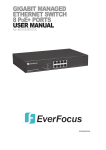
Gigabit / Fast Ethernet Switch
USER’S GUIDE
Twenty-four (24) 100BASE-TX w/ two (2) 1000BASE-T Switch
TABLE OF CONTENTS
1
UNPACKING INFORMATION ............................................................................................ 4
2
PRODUCT INTRODUCTION ............................................................................................. 4
2.1
KEY FEATURES .............................................................................................................. 4
2.2
THE FRONT PANEL ......................................................................................................... 5
2.2.1
1000BASE-T Ports ............................................................................................... 5
2.2.2
100BASE-TX Ports............................................................................................... 5
2.2.3
Cabling ................................................................................................................. 5
2.2.4
Status LEDs ......................................................................................................... 5
THE REAR PANEL ........................................................................................................... 6
3
2.3
2.3.1
ON/OFF ("Reset") Switch ..................................................................................... 6
2.3.2
Power Socket ....................................................................................................... 6
2.3.3
Fan ....................................................................................................................... 6
INSTALLATION.................................................................................................................. 6
3.1
3.2
4
SMART FUNCTION SETTINGS ........................................................................................ 7
4.1
5
6
7
2
TO LOCATE THE SWITCH ON A DESKTOP ............................................................................ 6
RACKMOUNT PLACEMENT................................................................................................ 6
START SMART FUNCTION ................................................................................................ 7
USE FUNCTION MENU ..................................................................................................... 8
5.1
MAIN MENU.................................................................................................................... 8
5.2
PORT SETUP.............................................................................................................. 8
5.3
VLAN SETUP .............................................................................................................11
5.4
TRUNKING SETUP ................................................................................................... 13
5.5
PRIORITY SETUP..................................................................................................... 15
5.6
LOAD DEFAULT ........................................................................................................ 17
5.7
RESET DEVICE ........................................................................................................ 17
HELPFUL SUGGESTIONS.............................................................................................. 17
6.1
6.2
PRIOR TO INSTALLATION................................................................................................ 17
FAST ETHERNET & GIGABIT ETHERNET .......................................................................... 17
6.3
MAC ADDRESS TABLE .................................................................................................. 18
6.4
SAMPLE APPLICATION ................................................................................................... 18
TROUBLESHOOTING ..................................................................................................... 19
Twenty-four (24) 100BASE-TX w/ two (2) 1000BASE-T Switch User's Guide
8
3
PRODUCT SPECIFICATIONS ......................................................................................... 20
Twenty-four (24) 100BASE-TX w/ two (2) 1000BASE-T Switch User's Guide
1 UNPACKING INFORMATION
Thank you for purchasing this Gigabit Switch. Before continuing, please check the contents of
the product package. This product package should contain the following items:
•
One (1) Switch
•
One (1) Power Cord
•
One (1) Console Cable
•
One (1) Four (4) Rubber Feet (for desktop placement)
•
One (1) Rackmount Kit
• This User’s Guide
If anything is missing, please contact your place of purchase immediately.
2 PRODUCT INTRODUCTION
2.1 Key Features
•
Port-Based VLAN supports up to 8 VLAN groups.
•
Built-in Trunking function supports up to 4 Trunking groups.
•
24 ports 100BASE-TX support 100Mbps/10Mbps Full-/Half-Duplex operation.
•
Port A,B 1000BASE-T support 1000Mbps/100Mbps/10Mbps Full-Duplex operation.
•
Auto-Negotiation support for each TP port.
•
Store-and-Forward technology eliminates bad packets.
•
12 Mbytes buffer memory shared.
•
IEEE 802.3x Flow Control support for Full-Duplex operation.
•
Back-Pressure Flow Control support for Half-Duplex operation.
•
16K MAC address table (max.) quickly pinpoints destination port for each packet.
4
Twenty-four (24) 100BASE-TX w/ two (2) 1000BASE-T Switch User's Guide
•
All TP ports support automatic MDI cross-over function for all modes of operation.
•
CoS supports two priority levels for each port.
•
Provides console port for easy configuration.
2.2 The Front Panel
2.2.1 1000BASE-T Ports
1000BASE-T is primarily used for network backbone connections. Each 1000BASE-T support
1000Mbps/100Mbps/10Mbps Full-Duplex mode, which provides an Auto-Negotiation and
auto-MDIX functions that sense for the attached device's maximum operating speed and
automatically sets the Switch to operate at that speed. Users only need to connect a network
cable into any TP port, and the functions will do the rest.
2.2.2 100BASE-TX Ports
Each 100BASE-TX port provides an Auto-Negotiation function that senses 100/10Mbps
Full-/Half-Duplex for the attached device's maximum operating speed and automatically sets
the Switch to operate at that speed. Users only need to connect a network device into any TP
port.
2.2.3 Cabling
Port Type
Cable Type
Connector
1000BASE-T Cat.5 TP
RJ-45
100BASE-TX Cat.5 TP
RJ-45
10BASE-T
Category 3, 4 or 5 TP RJ-45
Note: Category 5 TP cable recommended whenever installing new cabling.
To transmit at 1000Mbps requires Category 5 TP cable using four (4) pair wires.
2.2.4 Status LEDs
This Switch comes with a complete range of LEDs. The table below lists each LEDs name,
color and a brief description of its function.
Name
Color
Function
PWR
Green
Lit: Power "On"
Ports 1~24
Green
Lit: When the port has a valid physical connection with another device.
LINK/ACT
Ports 1~24
Blinks: When the port is sending or receiving data (Activity).
Amber
FD/COL
Ports A,B
Lit: When the port is set to Full-Duplex mode.
Blinks: When a collision is detected in Half-Duplex mode.
Green
Lit: When the port has a valid physical connection with another device at 1000Mbps.
1000
5
Twenty-four (24) 100BASE-TX w/ two (2) 1000BASE-T Switch User's Guide
Ports A,B
Green
Lit: When the port has a valid physical connection with another device at 100Mbps.
Amber
Lit: When the port has a valid physical connection with another device at 10Mbps.
Green
Lit: When the port is set to Full-Duplex mode.
Green
Lit: When the port has a valid physical connection with another device.
100
Ports A,B
10
Ports A,B
FD
Ports A,B
LK/ACT
Blink: When the port is sending or receiving data (Activity).
2.3 The Rear Panel
2.3.1 ON/OFF ("Reset") Switch
The power ON/OFF switch is located to the far right of the rear panel - next to the power
connector.
To Reset the Switch, turn the power switch "OFF", then "ON".
Note: The Switch must be reset when the MAC address table needs to be rebuilt.
2.3.2 Power Socket
The Power Socket is designed to be used with the power cord included in the product package.
•
Attach the female end of the power cord to the male power connector on the back panel.
• Attatch the male end of the power cord to a grounded power outlet.
2.3.3 Fan
Note: Please keep the fan area clear, so that the cooling function is not impaired.
3 INSTALLATION
3.1 To Locate the switch on a desktop
•
Attach the four (4) rubber feet included in the product package to the bottom of the Switch,
one in each corner.
•
Place the Switch on a clean, flat desk or tabletop close to a power outlet.
•
Plug in all network connections and the power cord.
•
Turn the power switch to "On."
3.2 Rackmount placement
•
Attach one (1) rackmounting bracket on each side of the Switch front panel and secure each
6
Twenty-four (24) 100BASE-TX w/ two (2) 1000BASE-T Switch User's Guide
bracket with the provided screws.
•
Use the other provided screws to secure each Switch to the rack.
4 SMART FUNCTION SETTINGS
4.1 Start Smart Function
The Switch has a smart function that you can use to manage your local area network (LAN )
more effectively. You also can use the default setting to make the Switch operate as a dumb
switch.
If you want to use smart function, install the Switch as below:
•
Use the “RS-232” connector to connect the Switch to a computer. Connect one (1) cable end
to the Switch, and connect the other end to the computer’s “COM1” or “COM2” port.
Note: If your Windows program doesn’t have a hyper terminal, you have to install it first.
•
Power “ON” the Switch
•
Execute the “HyperTerminal” program:
Start Menu ! Application Program ! Communication
•
! Hyper Terminal
Setup the connection content of Hyper Terminal:
" In connection tag, select which “COM” port is used to connect PC and the Switch.
"
Then press the “SETUP” button, set “Bits per second” to 9600, “Data bits” to 8, “Parity”
to None, “Stop bits” to 1, “Flow control” to None.
7
Twenty-four (24) 100BASE-TX w/ two (2) 1000BASE-T Switch User's Guide
•
After finishing the setting-up action in Hyper Terminal window, press any key to continue.
Now the computer can connect to Switch and use the user interface menu to select control
function.
5 USE FUNCTION MENU
5.1 Main menu
The main menu function selections are listed below:
1. PORT SETUP
2. VLAN SETUP
3. TRUNKING SETUP
4. PRIORITY SETUP
5. LOAD DEFAULT
6. RESET DEVICE
After you connect the Switch through the console port, the following screen shows up on the
monitor:
>>>>>>>>!35.QPSU!210211N!,!3H!TXJUDI!!>>>>>>>>!
!
!!!!!!!!!2/!QPSU!TFUVQ!
!
!!!!!!!!!3/!WMBO!TFUVQ!
!
!!!!!!!!!4/!USVOLJOH!TFUVQ!
!
!!!!!!!!!5/!QSJPSJUZ!TFUVQ!
!
!!!!!!!!!6/!MPBE!EFGBVMU!
!
!!!!!!!!!7/!SFTFU!EFWJDF!
Tfmfdu)2-3///7*@!
5.2 PORT SETUP
If you select “1” for “PORT SETUP” from the main menu, you’ll see the menu below:
8
Twenty-four (24) 100BASE-TX w/ two (2) 1000BASE-T Switch User's Guide
>>>>>>!Qpsu!Dvssfou!Tfuujoh!Jogp!>>>>>>!
!
!!!!!!!!!2!!3!!4!!5!!6!!7!!8!!9!!:!21!22!23!24!25!26!27!28!29!2:!31!32!33!34!35!
!!!BVUP!!T!!T!!T!!T!!T!!T!!T!!T!!T!!T!!T!!T!!T!!T!!T!!T!!T!!T!!T!!T!!T!!T!!T!!T!
211NGEY!!/!!/!!/!!/!!/!!/!!/!!/!!/!!/!!/!!/!!/!!/!!/!!/!!/!!/!!/!!/!!/!!/!!/!!/!
211NIEY!!/!!/!!/!!/!!/!!/!!/!!/!!/!!/!!/!!/!!/!!/!!/!!/!!/!!/!!/!!/!!/!!/!!/!!/!
!21NGEY!!/!!/!!/!!/!!/!!/!!/!!/!!/!!/!!/!!/!!/!!/!!/!!/!!/!!/!!/!!/!!/!!/!!/!!/!
!21NIEY!!/!!/!!/!!/!!/!!/!!/!!/!!/!!/!!/!!/!!/!!/!!/!!/!!/!!/!!/!!/!!/!!/!!/!!/!
!
!!!!!!T>Dvssfou!Tfuujoh!
!
Foufs!Qpsu!Ovncfs)235*;!
In the “Port Current Setting Info” menu, “S” represents “Current Setting”. The default setting is
that all the ports (from 1 to 24) are set to “AUTO”. “AUTO” means Auto-Negotiation for
Auto-Detect the connection speed and operation mode.
The table below lists the explanation of the items shown in the menu:
item
explanation
1~24
10/100Mbps port 1 to port 24
S
Current Setting
AUTO
Auto-Negotiation Enable
100MFDX
Force 100Mbps Full-Duplex Mode
100MHDX
Force 100Mbps Half-Duplex Mode
10MFDX
Force 10Mbps Full-Duplex Mode
10MHDX
Force 10Mbps Half-Duplex Mode
Note: If you set up 100MFDX, 100MHDX, 10MFDX or 10MHDX for the port, the device
connected to the other end of the cable must be set to the same speed and Duplex modes.
If you select “1” for setting port number 1, you’ll see the menu below:
9
Twenty-four (24) 100BASE-TX w/ two (2) 1000BASE-T Switch User's Guide
>>>>>>!Qpsu!Dvssfou!Tfuujoh!Jogp!>>>>>>!
!
!!!!!!!!!2!!3!!4!!5!!6!!7!!8!!9!!:!21!22!23!24!25!26!27!28!29!2:!31!32!33!34!35!
!!!BVUP!!T!!T!!T!!T!!T!!T!!T!!T!!T!!T!!T!!T!!T!!T!!T!!T!!T!!T!!T!!T!!T!!T!!T!!T!
211NGEY!!/!!/!!/!!/!!/!!/!!/!!/!!/!!/!!/!!/!!/!!/!!/!!/!!/!!/!!/!!/!!/!!/!!/!!/!
211NIEY!!/!!/!!/!!/!!/!!/!!/!!/!!/!!/!!/!!/!!/!!/!!/!!/!!/!!/!!/!!/!!/!!/!!/!!/!
!21NGEY!!/!!/!!/!!/!!/!!/!!/!!/!!/!!/!!/!!/!!/!!/!!/!!/!!/!!/!!/!!/!!/!!/!!/!!/!
!21NIEY!!/!!/!!/!!/!!/!!/!!/!!/!!/!!/!!/!!/!!/!!/!!/!!/!!/!!/!!/!!/!!/!!/!!/!!/!
!
!!!!!!T>Dvssfou!Tfuujoh!
!
Foufs!Qpsu!Ovncfs)235*;!
........................................!
Qpsu!Tfmfdujpo!Jufnt;!
2/Bvup.Ofhpujbujpo!Fobcmf!
3/Gpsdf!211N`GEY!Npef!
4/Gpsdf!211N`IEY!Npef!
5/Gpsdf!21N`GEY!Npef!
6/Gpsdf!21N`IEY!Npef!
7/FYJU!
Tfmfdu)2-3///7*@!
If you select “2” for “Force 100M_FDX Mode”, you’ll see the menu below:
>>>>>>!Qpsu!Dvssfou!Tfuujoh!Jogp!>>>>>>!
!
!!!!!!!!!2!!3!!4!!5!!6!!7!!8!!9!!:!21!22!23!24!25!26!27!28!29!2:!31!32!33!34!35!
!!!BVUP!!/!!T!!T!!T!!T!!T!!T!!T!!T!!T!!T!!T!!T!!T!!T!!T!!T!!T!!T!!T!!T!!T!!T!!T!
211NGEY!!T!!/!!/!!/!!/!!/!!/!!/!!/!!/!!/!!/!!/!!/!!/!!/!!/!!/!!/!!/!!/!!/!!/!!/!
211NIEY!!/!!/!!/!!/!!/!!/!!/!!/!!/!!/!!/!!/!!/!!/!!/!!/!!/!!/!!/!!/!!/!!/!!/!!/!
!21NGEY!!/!!/!!/!!/!!/!!/!!/!!/!!/!!/!!/!!/!!/!!/!!/!!/!!/!!/!!/!!/!!/!!/!!/!!/!
!21NIEY!!/!!/!!/!!/!!/!!/!!/!!/!!/!!/!!/!!/!!/!!/!!/!!/!!/!!/!!/!!/!!/!!/!!/!!/!
!
!!!!!!T>Dvssfou!Tfuujoh!
!
Foufs!Qpsu!Ovncfs)235*;
You can see in the menu above, the current setting of port 1 has been changed from “AUTO” to
“100MFDX”, which means you have forced port 1 to operate at 100Mbps Full-Duplex Mode.
10 Twenty-four (24) 100BASE-TX w/ two (2) 1000BASE-T Switch User's Guide
You can press “Enter” to EXIT the menu back to main menu.
5.3 VLAN SETUP
In the main menu, If you select “2” for “VLAN SETUP”, you’ll see the menu below:
>>>>>>>>>>>>>>>!Dvssfou!WMBO!HSPVQ!Tfuujoh!Tubuvt!>>>>>>>>>>>>>>!
!
WMBO`JE0Txjudi!Qpsu!
!
!!!2!!3!!4!!5!!6!!7!!8!!9!!:!21!22!23!24!25!26!27!28!29!2:!31!32!33!34!35!36!37!
2!!Y!!Y!!Y!!Y!!Y!!Y!!Y!!Y!!Y!!Y!!Y!!Y!!Y!!Y!!Y!!Y!!Y!!Y!!Y!!Y!!Y!!Y!!Y!!Y!!Y!!Y!
3!!/!!/!!/!!/!!/!!/!!/!!/!!/!!/!!/!!/!!/!!/!!/!!/!!/!!/!!/!!/!!/!!/!!/!!/!!/!!/!
4!!/!!/!!/!!/!!/!!/!!/!!/!!/!!/!!/!!/!!/!!/!!/!!/!!/!!/!!/!!/!!/!!/!!/!!/!!/!!/!
5!!/!!/!!/!!/!!/!!/!!/!!/!!/!!/!!/!!/!!/!!/!!/!!/!!/!!/!!/!!/!!/!!/!!/!!/!!/!!/!
6!!/!!/!!/!!/!!/!!/!!/!!/!!/!!/!!/!!/!!/!!/!!/!!/!!/!!/!!/!!/!!/!!/!!/!!/!!/!!/!
7!!/!!/!!/!!/!!/!!/!!/!!/!!/!!/!!/!!/!!/!!/!!/!!/!!/!!/!!/!!/!!/!!/!!/!!/!!/!!/!
8!!/!!/!!/!!/!!/!!/!!/!!/!!/!!/!!/!!/!!/!!/!!/!!/!!/!!/!!/!!/!!/!!/!!/!!/!!/!!/!
9!!/!!/!!/!!/!!/!!/!!/!!/!!/!!/!!/!!/!!/!!/!!/!!/!!/!!/!!/!!/!!/!!/!!/!!/!!/!!/!
!
Foufs!Qpsu!Ovncfs)235-36-37*;!
The table below lists the explanation of the items shown in the menu:
item
explanation
1~24 (row)
10/100Mbps port 1 to port 24
25,26 (row)
1000Mbps port A, B
1~8 (column)
VLAN group 1 to 8
X
It means the VLAN group assignment of the port
If you select “1” for port 1 setting, you’ll see the menu below:
11 Twenty-four (24) 100BASE-TX w/ two (2) 1000BASE-T Switch User's Guide
>>>>>>>>>>>>>>>!Dvssfou!WMBO!HSPVQ!Tfuujoh!Tubuvt!>>>>>>>>>>>>>>!
!
WMBO`JE0Txjudi!Qpsu!
!
!!!2!!3!!4!!5!!6!!7!!8!!9!!:!21!22!23!24!25!26!27!28!29!2:!31!32!33!34!35!36!37!
2!!Y!!Y!!Y!!Y!!Y!!Y!!Y!!Y!!Y!!Y!!Y!!Y!!Y!!Y!!Y!!Y!!Y!!Y!!Y!!Y!!Y!!Y!!Y!!Y!!Y!!Y!
3!!/!!/!!/!!/!!/!!/!!/!!/!!/!!/!!/!!/!!/!!/!!/!!/!!/!!/!!/!!/!!/!!/!!/!!/!!/!!/!
4!!/!!/!!/!!/!!/!!/!!/!!/!!/!!/!!/!!/!!/!!/!!/!!/!!/!!/!!/!!/!!/!!/!!/!!/!!/!!/!
5!!/!!/!!/!!/!!/!!/!!/!!/!!/!!/!!/!!/!!/!!/!!/!!/!!/!!/!!/!!/!!/!!/!!/!!/!!/!!/!
6!!/!!/!!/!!/!!/!!/!!/!!/!!/!!/!!/!!/!!/!!/!!/!!/!!/!!/!!/!!/!!/!!/!!/!!/!!/!!/!
7!!/!!/!!/!!/!!/!!/!!/!!/!!/!!/!!/!!/!!/!!/!!/!!/!!/!!/!!/!!/!!/!!/!!/!!/!!/!!/!
8!!/!!/!!/!!/!!/!!/!!/!!/!!/!!/!!/!!/!!/!!/!!/!!/!!/!!/!!/!!/!!/!!/!!/!!/!!/!!/!
9!!/!!/!!/!!/!!/!!/!!/!!/!!/!!/!!/!!/!!/!!/!!/!!/!!/!!/!!/!!/!!/!!/!!/!!/!!/!!/!
!
Foufs!Qpsu!Ovncfs)235-36-37*;2!
Foufs!WMBO!Hspvq)2.9*;!
!
!2/!Bee!Qpsu!Up!WMBO!
!3/!Sfnpwf!Qpsu!Gspn!WMBO!
!4/!Fyju!
!!!!Tfmfdu)2-3-4*@!
Now you can modify the VLAN group assignment of port 1 by entering the VLAN group (1~8)
that you want to modify. There are 3 choices for the modification and they are listed in the table
below:
item
explanation
Add Port To VLAN
Add the selection port to the VLAN group
Remove Port From VLAN
Remove the selection port to from the VLAN group
Exit
Exit this menu
As an example, by entering VLAN group 2 and selecting modification 1, you can see that port 1
is added to VLAN group 2 as shown in the following menu.
12 Twenty-four (24) 100BASE-TX w/ two (2) 1000BASE-T Switch User's Guide
>>>>>>>>>>>>>>>!Dvssfou!WMBO!HSPVQ!Tfuujoh!Tubuvt!>>>>>>>>>>>>>>!
!
WMBO`JE0Txjudi!Qpsu!
!
!!!2!!3!!4!!5!!6!!7!!8!!9!!:!21!22!23!24!25!26!27!28!29!2:!31!32!33!34!35!36!37!
2!!Y!!Y!!Y!!Y!!Y!!Y!!Y!!Y!!Y!!Y!!Y!!Y!!Y!!Y!!Y!!Y!!Y!!Y!!Y!!Y!!Y!!Y!!Y!!Y!!Y!!Y!
3!!Y!!/!!/!!/!!/!!/!!/!!/!!/!!/!!/!!/!!/!!/!!/!!/!!/!!/!!/!!/!!/!!/!!/!!/!!/!!/!
4!!/!!/!!/!!/!!/!!/!!/!!/!!/!!/!!/!!/!!/!!/!!/!!/!!/!!/!!/!!/!!/!!/!!/!!/!!/!!/!
5!!/!!/!!/!!/!!/!!/!!/!!/!!/!!/!!/!!/!!/!!/!!/!!/!!/!!/!!/!!/!!/!!/!!/!!/!!/!!/!
6!!/!!/!!/!!/!!/!!/!!/!!/!!/!!/!!/!!/!!/!!/!!/!!/!!/!!/!!/!!/!!/!!/!!/!!/!!/!!/!
7!!/!!/!!/!!/!!/!!/!!/!!/!!/!!/!!/!!/!!/!!/!!/!!/!!/!!/!!/!!/!!/!!/!!/!!/!!/!!/!
8!!/!!/!!/!!/!!/!!/!!/!!/!!/!!/!!/!!/!!/!!/!!/!!/!!/!!/!!/!!/!!/!!/!!/!!/!!/!!/!
9!!/!!/!!/!!/!!/!!/!!/!!/!!/!!/!!/!!/!!/!!/!!/!!/!!/!!/!!/!!/!!/!!/!!/!!/!!/!!/!
!
Foufs!Qpsu!Ovncfs)235-36-37*;!
5.4 TRUNKING SETUP
Note: If you need to aggregate ports as a Trunking group, be sure to set these ports in
the same VLAN group manually. If you do not set the trunking group ports to the same
VLAN group, the Switch will not operate properly.
If you select “3” for “TRUNKING SETUP” from the main menu, you’ll see the menu below:
Dvssfou!Usvoljoh!Qpsu!Tfuvq!Jogp;!
!
Usvoljoh!Qpsu`2!jt!ejtbcmfe!
Usvoljoh!Qpsu`3!jt!ejtbcmfe!
Usvoljoh!Qpsu`4!jt!ejtbcmfe!
Usvoljoh!Qpsu`5!jt!ejtbcmfe!
!
........................................!
2/Tfu!Usvoljoh!Qpsu`2!
3/Tfu!Usvoljoh!Qpsu`3!
4/Tfu!Usvoljoh!Qpsu`4!
5/Tfu!Usvoljoh!Qpsu`5!
6/FYJU!
Tfmfdu)2-3///6*@!
Above the dotted line shows the status of the Trunking Port. Under the dotted line shows 5
selections for your choice. You can select from 1 to 4 to set Trunking Port or 5 to EXIT the
13 Twenty-four (24) 100BASE-TX w/ two (2) 1000BASE-T Switch User's Guide
menu.
For example, if you select “1”, “Set Trunking Port_1”, you’ll see the menu below:
Dvssfou!Usvoljoh!Qpsu!Tfuvq!Jogp;!
!
Usvoljoh!Qpsu`2!jt!ejtbcmfe!
Usvoljoh!Qpsu`3!jt!ejtbcmfe!
Usvoljoh!Qpsu`4!jt!ejtbcmfe!
Usvoljoh!Qpsu`5!jt!ejtbcmfe!
!
........................................!
2/Tfu!Usvoljoh!Qpsu`2!
3/Tfu!Usvoljoh!Qpsu`3!
4/Tfu!Usvoljoh!Qpsu`4!
5/Tfu!Usvoljoh!Qpsu`5!
6/FYJU!
Tfmfdu)2-3///6*@!
..!Usvoljoh!Qpsu`2!Tfuvq!..!
2/Ejtbcmf!Usvoljoh!Gvodujpo/!
3/Qpsu!2-24!Gps!Usvoljoh!Qpsu`2/!
4/Qpsu!2-3-24-25!Gps!Usvoljoh!Qpsu`2/!
5/Qpsu!2-3-4-5-24-25-26-27!Gps!Usvoljoh!Qpsu`2/!
6/FYJU/Tfmfdu)2-3///6*@!
If you select “2”, “Port 1,13 For Trunking Port_1”, you’ll see the menu below:
14 Twenty-four (24) 100BASE-TX w/ two (2) 1000BASE-T Switch User's Guide
Dvssfou!Usvoljoh!Qpsu!Tfuvq!Jogp;!
!
Qpsu!2-24!Gps!Usvoljoh!Qpsu`2/!
Usvoljoh!Qpsu`3!jt!ejtbcmfe!
Usvoljoh!Qpsu`4!jt!ejtbcmfe!
Usvoljoh!Qpsu`5!jt!ejtbcmfe!
!
........................................!
2/Tfu!Usvoljoh!Qpsu`2!
3/Tfu!Usvoljoh!Qpsu`3!
4/Tfu!Usvoljoh!Qpsu`4!
5/Tfu!Usvoljoh!Qpsu`5!
6/FYJU!
Tfmfdu)2-3///6*@!
Now you have set port 1 and 13 as Trunking Port_1.
The table below lists the ports which can be set as a Trunking Port.
Trunking Port_1
Port 1,13
Port 1,2,13,14
Port 1,2,3,4,13,14,15,16
Trunking Port_2
Port 5,17
Port 5,6,17,18
Port 5,6,7,8,17,18,19,20
Trunking Port_3
Port 9,21
Port 9,10,21,22
Port 9,10,11,12,21,22,23,24
Trunking Port_4
Port A,B (G1,G2)
In the menu for Trunking Port_4 setting, it displays G1, G2 as Port A, B.
5.5 PRIORITY SETUP
If you select “4” for “PRIORITY SETUP” from the main menu, you’ll see the menu below:
15 Twenty-four (24) 100BASE-TX w/ two (2) 1000BASE-T Switch User's Guide
>>>>>>!Dvssfou!Qpsu!Qsjpsjuz!Tubuvt!>>>>>>!
!
!!2!!3!!4!!5!!6!!7!!8!!9!!:!21!22!23!24!25!26!27!28!29!2:!31!32!33!34!35!36!37!
!
!!/!!/!!/!!/!!/!!/!!/!!/!!/!!/!!/!!/!!/!!/!!/!!/!!/!!/!!/!!/!!/!!/!!/!!/!!/!!/!
!
!!!!++++++++!!I!>!IJHI!Qsjpsjuz!++++++++!
!
Foufs!Qpsu!Ovncfs)235-36-37*;!
The table below lists the explanation of the items show up in the menu:
item
explanation
1~24
Port 1 to 24
25,26
Port A,B
H
High Priority
If you select “1” for port 1 setting, you’ll see the menu below:
>>>>>>!Dvssfou!Qpsu!Qsjpsjuz!Tubuvt!>>>>>>!
!
!!2!!3!!4!!5!!6!!7!!8!!9!!:!21!22!23!24!25!26!27!28!29!2:!31!32!33!34!35!36!37!
!
!!/!!/!!/!!/!!/!!/!!/!!/!!/!!/!!/!!/!!/!!/!!/!!/!!/!!/!!/!!/!!/!!/!!/!!/!!/!!/!
!
!!!!++++++++!!I!>!IJHI!Qsjpsjuz!++++++++!
!
Foufs!Qpsu!Ovncfs)235-36-37*;2!
!
2/!TFU!IJHI!QSJPSJUZ!
3/!TFU!MPX!QSJPSJUZ!
4/!FYJU!
Tfmfdu)2-3-4*@!
Now you can set the port 1 as High or Low Priority. The default is Low Priority for all ports. If you
select “2”, “SET LOW PRIORITY”, it will not change anything. If you select “1”, “SET HIGH
PRIORITY” for port 1, you’ll see the menu below:
16 Twenty-four (24) 100BASE-TX w/ two (2) 1000BASE-T Switch User's Guide
>>>>>>!Dvssfou!Qpsu!Qsjpsjuz!Tubuvt!>>>>>>!
!
!!2!!3!!4!!5!!6!!7!!8!!9!!:!21!22!23!24!25!26!27!28!29!2:!31!32!33!34!35!36!37!
!
!!I!!/!!/!!/!!/!!/!!/!!/!!/!!/!!/!!/!!/!!/!!/!!/!!/!!/!!/!!/!!/!!/!!/!!/!!/!!/!
!
!!!!++++++++!!I!>!IJHI!Qsjpsjuz!++++++++!
!
Foufs!Qpsu!Ovncfs)235-36-37*;!
Now you can see the port 1 is set to High Priority.
5.6 LOAD DEFAULT
If you select “5” for “LOAD DEFAULT” from the main menu, you’ll see the menu below:
Mpbe!Efgbvmu!Tfuujoh!
!
!
“Load Default Setting” will clear all the settings and restore back to factory settings. Please wait
a while, it will go back to the main menu.
5.7 RESET DEVICE
If you select “6” for “RESET DEVICE” from the main menu, it will reset the switch.
6 HELPFUL SUGGESTIONS
6.1 Prior to Installation
Before installing the Switch and connecting network devices, it is important to plan the
network's layout. Things you should consider include:
•
Dedicated Bandwidth: File servers and other high-traffic hardware improve their
performance if they have their own dedicated 10Mbps,100Mbps, or 1000Mbps bandwidth.
•
Full-Duplex: Determine which devices support Full-Duplex connections.
•
Fast Ethernet & Gigabit Ethernet: Make sure rules for cable lengths and categories are
followed. 100BASE-TX and 1000BASE-T have the same rules for cable and distance.
•
Auto-Negotiation: Devices with different speeds may be easily swapped when the other
end of the cable is fixed to a port with Auto-Negotiation.
•
Uplink: The switch can be uplinked to another switch or hub using each of the 100/10Mbps
TP port or the Gigabit Ethernet ports (port A,B) with regular or cross-over cable.
6.2 Fast Ethernet & Gigabit Ethernet
1000BASE-T is called "Gigabit Ethernet". In Gigabit Ethernet, data travels ten times faster
(1000Mbps) than in Fast Ethernet (100Mbps).
17 Twenty-four (24) 100BASE-TX w/ two (2) 1000BASE-T Switch User's Guide
100BASE-TX is called "Fast Ethernet". In Fast Ethernet, data travels ten times faster (100Mbps)
than in traditional Ethernet (10Mbps).
Note: If your 10BASE-T network currently uses Category 5 TP cabling, you can instantly
upgrade the network to a 100BASE-TX network by changing network devices.
Note: Both 100BASE-TX and 1000BASE-T use Category 5 TP cabling. But 1000BASE-T must
use four pairs twist pair wire. You should check that the Category 5 TP cabling you are using
has four pairs wire before you connect to a Gigabit device.
6.3 MAC Address Table
Every Ethernet data packet includes both source and destination addresses. This six (6) bytes
ID is called the MAC (Media Access Control) Address.
The Switch can automatically learn and store MAC addresses. However, the MAC address
table is volatile: it disappears when the Switch is powered “OFF” or reset.
Note: When the network needs reconfiguration, we recommend turning off the power first. After
all nodes have been moved, turn the Switch back "ON" to rebuild the internal MAC address
table.
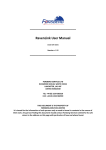
6.4 Sample Application
The optimal application for the Switch is as a "Big-Pipe" backbone interconnecting file servers
with bandwidth-hungry workgroups, departments, and offices.
18 Twenty-four (24) 100BASE-TX w/ two (2) 1000BASE-T Switch User's Guide
7 Troubleshooting
Link LED does not lit after cable is connected to the port.
•
Verify that the other end of the cable is connected to a device that is powered on and
on-line.
100BASE-TX port Link LED is lit, Collision LED is blinking, but traffic is irregular.
•
Check that the attached device is not set to dedicated Full-Duplex. (Some devices use a
physical or software switch to change Duplex modes. Auto-Negotiation may not recognize
19 Twenty-four (24) 100BASE-TX w/ two (2) 1000BASE-T Switch User's Guide
this type of Full-Duplex setting).
Note: For any change to DIP switch settings to take effect, the Switch must be turned “OFF”,
then “ON” again.
Always check that:
•
Cable and link distances are within the network’s specifications
•
Overall network diameters are within the network’s specification.
8 Product specifications
Models
24 ports 100BASE-TX w/ 2 1000BASE-T Gigabit Switch
Standards
•
10BASE-T IEEE802.3
•
100BASE-TX IEEE802.3u
•
1000BASE-T IEEE802.3ab
•
Flow Control IEEE802.3x
•
Twenty-four (24) 100BASE-TX
•
Two (2) 1000BASE-T
•
10BASE-T: Cat. 3, 4 or 5 TP
•
1000BASE-T/100BASE-TX: Cat. 5 TP
•
1000BASE-T 2000/200/20Mbps
•
100BASE-TX 200/100/20/10Mbps
Ports
Media support
Bandwidth
Forwarding/Filtering Rate •
1488100 packets/second per port@1000Mbps max.
•
148810 packets/second per port@100Mbps max.
•
14881 packets/second per port@10Mbps max.
•
2.6µsec@ 1000Mbps min.
•
11µsec@100Mbps min.
•
75µsec@10Mbps min.
MAC Addresses
•
16K six (6)-bytes entries maximum, Self-Learning
Buffer memory
•
12 Mbytes
Duplex Modes
•
Auto-Negotiation
Crossover
•
Auto-Crossover function for each port
Switch
•
One (1) for Power
LED Indicators
• One (1) for display PWR status
For port 1 to 24 (100/10Mbps ports):
Latency
•
One (1) per port for display LINK/ACT status
• One (1) per port for display FD/COL status
For port A, B (1000/100/10Mbps ports):
•
One (1) per port for display speed 1000Mbps
20 Twenty-four (24) 100BASE-TX w/ two (2) 1000BASE-T Switch User's Guide
•
One (1) per port for display speed 100Mbps
•
One (1) per port for display speed 10Mbps
•
One (1) per port for display Full-Duplex
•
One (1) per port for display LK/ACT status
•
Full range Auto-Switching
•
Input voltage: 100~240 +/-10%V AC/50~60Hz
Power Consumption
•
52.9W max.
Environment
•
Operating temp: 0~45°C(32~113°F)
•
Storage temp: -20~70°C(-4~158°F)
•
Humidity: 10%~90% non-condensing
•
FCC Class A
•
CE Mark
•
440x205x44mm (17.32x8.07x1.73 inches)
Power Supply
Certifications
Dimensions
21 Twenty-four (24) 100BASE-TX w/ two (2) 1000BASE-T Switch User's Guide
FCC WARNING
This equipm ent has been tested and f ound to com ply with the limits for a Class A com puting device pur suant to P ar t 15 of FCC
Rules, which ar e designed to pr ovide r easonable pr otection against electr om agnetic interf er ence in a comm ercial environm ent.
Changes or m odifications to the equipm ent not expr essly appr oved by the party responsible f or com pliance could void the
user 's authority to operate the equipm ent.
CE MARK WARNING
This is a Class A pr oduct. In a dom estic environm ent this pr oduct m ay cause r adio interfer ence in which case the user m ay be
requir ed to take adequate m easures.
22 Twenty-four (24) 100BASE-TX w/ two (2) 1000BASE-T Switch User's Guide