1
Titan
Commander
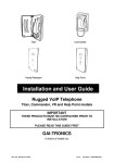
Installation and User Guide
Titan Telephone (1088)
Commander Telephone (1089)
SMART models
GAI-TRONICS
.
Doc. No. 502-20-0114-001
Iss2.
Dec 2007 (CN33056-001)
CONTENTS
1.
Safety and Care Information....................................................................... 4
2.
Product Description .................................................................................... 4
3.
Changes from previous versions.................................................. 5
2.2.
Titan features ............................................................................... 5
2.3.
Commander features.................................................................... 6
Operation / Testing ..................................................................................... 6
3.1.
Making and Receiving calls.......................................................... 6
3.2.
Last Number Redial ..................................................................... 6
3.3.
Secrecy (Mute) ............................................................................. 6
3.4.
Recall Function ............................................................................ 6
3.5.
Call timer ...................................................................................... 7
4.
SMART features ......................................................................................... 7
5.
Installation .................................................................................................. 7
6.
7.
2
2.1.
5.1.
General ........................................................................................ 7
5.2.
Emergency Services warning....................................................... 8
5.3.
Titan ............................................................................................. 8
5.4.
Commander ............................................................................... 10
Mounting methods and dimensions .......................................................... 10
6.1.
General ...................................................................................... 10
6.2.
Titan ........................................................................................... 11
6.3.
Commander ............................................................................... 15
Connections ............................................................................................. 17
7.1.
Standard connections................................................................. 18
7.2.
Additional hook contact .............................................................. 19
7.3.
Optional external inputs.............................................................. 19
7.4.
Optional signal outputs............................................................... 20
7.5.
Supplementary Power supply..................................................... 20
Titan, Commander, SMART
8.
Programming and Option Settings............................................................ 20
8.1.
Quick Programming Guide (using a tone phone). ...................... 20
8.2.
Further programming options ..................................................... 22
8.3.
TMA............................................................................................ 22
9.
Aftercare................................................................................................... 23
10.
Technical Specifications ........................................................................... 24
11.
CE Declaration ......................................................................................... 27
Titan, Commander, SMART
3
1.
Safety and Care Information
▲
▲
▲
The safety of the user/installer relies on the isolation of the telephone
network and not on the earthing of the case
▲
Telephone network voltages can be hazardous. Take adequate
precautions when opening the case or installing. If in doubt, disconnect
the telephone line elsewhere before accessing the line connections.
▲
For increased protection against lightning transients, attach a local
earth to the main terminal block (see section 7)
2.
The spring-loaded door (Titan models only, where fitted) can close
sharply. Take care not to trap fingers etc., during installation and use.
Please read these instructions thoroughly before starting installation.
These products must be installed by competent personnel familiar with
telephone installation.
Product Description
This manual describes SMART versions of the Titan and Commander
telephone ranges. SMART stands for Self Monitoring And Reporting
Telephone - a family of intelligent, processor-based products giving many
advanced features from a line -powered analog telephone. Models are
available with full numeric keypads for manual dialling, with auto-dial buttons
for dialling pre-stored numbers from a single button press, or without any
buttons. Common keypad layouts are shown below.
Although functionally and electrically identical, (i.e. the operation,
programming and connection details are common), Titan and Commander
differ physically, so the installation and mounting details are described
separately.
4
Titan, Commander, SMART
2.1. Changes from previous versions
This manual describes an updated range of products introduced in June 2006.
For those familiar with GAI-Tronics’ products, the list of new or changed
features is as follows:
•
New terminal layout (section 7.1).
•
Increased lightning protection (section 10).
•
No separate Cap-Shunt link (ringing is permanently enabled).
•
Compliance with railway EMC standards (section 10)
•
Second hookswitch option (section 7.2)
•
Optional additional inputs and outputs
•
RoHS compliant
For the full list of product features, please see the specifications in section 10.
2.2. Titan features
Titan is a family of rugged, weather-resistant metal-bodied telephones
available with a range of handset types, keypad configurations, colours and
enclosures, based around a common faceplate style.
Most Titans are equipped with a heavy-duty spring-loaded door, but models
are available without door and also as faceplate only, for flush mounting.
Titan doors may be fitted with slamlocks opened by an 8mm square socket
key.
Titan, Commander, SMART
5
2.3. Commander features
Commander is a family of rugged, weather-resistant telephones manufactured
from moulded glass-reinforced polyester. A range of handset types and
keypad configurations are available.
3.
Operation / Testing
3.1. Making and Receiving calls
To make a call, lift the handset, wait for dial tone, dial required digits (or press
required memory button or Last Number Redial where provided) and wait for
connection.
To end a call, replace the handset in its cradle.
To receive a call, lift the handset when ringing is heard.
3.2. Last Number Redial
(15 and 18 button versions only)
Lift the handset, press LR to redial the last dialled number.
3.3. Secrecy (Mute)
(15 and 18 button versions only)
•
During a call, press and hold the S button to mute the microphone.
3.4. Recall Function
(15 and 18 button versions only)
6
Titan, Commander, SMART
When a call is in progress, press R to send a “recall” signal to the exchange.
Only time-break recall signals can be generated. The factory default recall
break is 100ms, but can be set to other values (see section).
3.5. Call timer
The phone has a programmable call timer that can limit the maximum call
duration.
When ON, the timer forces the phone back off line after the preset time. This
prevents the line remaining tied if the handset is left off-hook. The timer is
factory-set to 7mins by default, but can be set to any value (up to 2¾hrs) or
disabled. See section 8.2.1.
4.
SMART features
This family of products has a wide range of intelligent features including:
•
Monitoring of faults and health status
•
Remote programming of auto-dial numbers and configuration parameters
•
Alternate day / night autodial numbers
•
Call logs for calls made to and from the telephones
These features are all available over standard, 2 wire telephone lines with no
external power required at the phone.
To use these features, GAI-Tronics provide a Telephone Management
Application (TMS) available separately, see section 8.3.
5.
Installation
5.1. General
IMPORTANT
All possible measures must be taken to ensure water, fluid or dust
does not contaminate the internal components of the telephone whilst
unpacking, preparing and installing the telephone in inclement weather
conditions or by negligence.
Failure to do so may invalidate your warranty.
These telephones are supplied without connection leads – cabling to the
telephone network must be supplied and installed by the installer. Because of
this, extra precautions must be observed: installers must ensure that they
have the permission of the owner of the PABX or telephone network to which
the telephone is to be connected, and that installation is carried out by trained
personnel. Contact GAI-Tronics if installation service is required.
Titan, Commander, SMART
7
IMPORTANT
Installation details differ between the TITAN and COMMANDER product
ranges –please make sure you know which product you are installing
and refer to the appropriate sections below.
5.2. Emergency Services warning
If the telephone is configured so that it cannot make a direct call to the
emergency services, check with your telephone service provider or
infrastructure maintainer whether it is necessary to warn users, and if so
provide a suitable warning notice. A warning label, which can be fixed
to the front of the telephone, is provided.
5.3. Titan
1.
To prepare for installation, open the door (where fitted), then undo the
four retaining screws to remove the faceplate from the rear enclosure. A
3mm Allen key is required.
Caution – take care to support the spring-loaded door whilst open
to prevent it slamming shut and trapping fingers.
8
Titan, Commander, SMART
2.
All connections are on the lower edge of the circuit board on the rear of
the faceplate.
3.
The Titan telephone is intended for vertical installation to a wall or pole.
Select the required mounting method (section 6) and mount the rear
enclosure first where applicable.
4.
Route the required cables through glands as appropriate, and make
connections following section 7.
5.
Re-fit the faceplate ensuring a weatherproof seal
6.
Programming or parameter changes can be made remotely, using a
tone phone or TMA (see section)
7.
Test the operation of the telephone (section 3). Installation is now
complete.
Titan, Commander, SMART
9
5.4. Commander
1.
All connections are on the circuit board housed in the front casing.
Ringer
Ringer connector
Circuit board
(PCB)
HD3 - Aux. outputs
(optional)
HD14 - Aux. inputs
(optional)
6.
CON1 - Main
Terminal block
TB2 - Additional
hookswitch
(Optional)
2.
To prepare for installation, undo the three retaining screws shown to
remove the front casing from the rear. The screws are captive in the
front casing; a 5mm Allen key is required. Disconnect the ringer
connector from the circuit board, noting the position and orientation.
3.
The Commander telephone can be installed vertically to a wall or pole,
or used horizontally on a desk. Select the required mounting method
(section 6) and mount the rear casing first where applicable.
4.
Route the required cables through glands as appropriate, and make
connections following section 7.
5.
Reconnect the ringer. Re-secure the telephone Front Casing to the
Rear Casing with the three retaining screws, ensuring a weatherproof
seal.Programming or parameter changes can be made remotely, using a
tone phone or TMA (see section)
6.
Test the operation of the telephone (section 3). Installation is now
complete.
Mounting methods and dimensions
6.1. General
IMPORTANT
Installation details differ between the TITAN and COMMANDER product
ranges –please make sure you know which product you are installing
and refer to the appropriate sections below.
10
Titan, Commander, SMART
Before mounting the telephone, check the cable routing and requirements. If
glands are required, fit them to the case as follows:
1. Remove the RED blanking plug leaving the other (usually BLACK) in
place.
Only fit a second gland if a separate cable is required to the phone (for
example for an additional hook contact).
2. Select the appropriate sized gland:
Use the smaller gland for cables
diameters 4 - 7mm.
Use the larger gland for cable
diameters 8 - 13mm.
3. From the outside of the case, insert
the selected gland into the threaded
cable entry hole and tighten, so that
its sealing washer is compressed
against the enclosure surface.
4. Proceed with chosen mounting method below
6.2. Titan
As standard, Titan with rear enclosure is supplied with 2 cable glands with
sealing washers, 4 countersunk screws with wall plugs and a 3mm Allen key.
Titan telephones supplied for flush mounting have no rear enclosure – see
section 6.2.3 below.
Titan, Commander, SMART
11
6.2.1
Wall mounting
1. Using a suitable tool, punch out the 4 holes in the rear enclosure,
taking care not to damage or dislodge the plastic bushes. Only four
of the eight holes are required - the outer ones are recommended.
The inner holes are provided to be compatible with older-style
mounting posts, and should be left intact if not used. If the inner
holes are used they must be fitted with the supplied plastic bushes.
WARNING:.Your warranty will be invalidated if :1. Any fixing hole made in the rear enclosure is left unused.
2. Any additional holes are drilled into the telephone enclosure.
3. Plastic bushes are not used on all fixing holes.
2. Mark the wall with hole centres based on the dimensions shown
(145 x 270mm). If necessary offer the rear enclosure up to the wall
to check alignment. Do not use the enclosure as a template for
drilling.
3. Drill holes in the wall on the marked positions. Select appropriate
screws, wall plugs etc., for the type of wall, bearing in mind that the
weight of the complete phone is around 5kg.
IMPORTANT: USE ONLY countersunk-headed fixing screws. Check
that screws seat properly in the plastic bushes to ensure a
watertight seal. Do not use excessive tightening force, as this may
crack the case.
12
Titan, Commander, SMART
4. Ensure that all four plastic flanged bushes are in place and the rear
enclosure is screwed tightly to the surface to prevent any water
ingress through the punched holes.
5. Complete the installation by making the appropriate connections
(section 7) and re-fitting the face plate.
6.2.2
Pole mounting
Kit No 100-02-0208-001
This accessory is for mounting GAI-Tronics telephones on to the side of
round poles of 100mm to 200mm diameter, or on to square or
rectangular section uprights of 100mm to 150mm across the mounting
surface.
NOTE:
Banding straps (large scale worm-drive clamps) are not included in this
kit and must be obtained separately. For details of where banding can
be obtained, refer to GAI-Tronics.
1. After punching through the flanged bushes in the rear enclosure (as
described in WALL MOUNTING), attach the pole mounting clamp
assemblies to the rear enclosure using the M6 x 25 screws
provided. Tighten to a torque of 4.5Nm max.
Note: only use the outer four holes, and ensure that the screws seat
properly in the plastic bushes to avoid water ingress.
Titan, Commander, SMART
13
2. Ensuring that the glands are at the bottom, pass a proprietary
banding strap round each of the pole mounting clamps and the
support pole. Tighten securely.
3. Continue the installation by making the appropriate connections
(section 7) and re-fitting the face plate.
4. Re-tighten the straps firmly and trim off any excess band material.
For security the driving head of the band may also be sawn off.
6.2.3
Flush mounting
Titan telephones supplied for flush mounting have a slightly different
faceplate to those supplied with a rear enclosure – in particular the fixing
holes are in different positions and there are no corner cut-outs (for door
hinges). These models are usually described as “Titan fp” and the
supplied mounting kit contains round-headed screws and no glands.
To flush-mount the telephone to a wall:
1. Prepare a recess (at least 50mm deep) in the wall according to the
dimensions shown.
2. Mark the wall with hole centres based on the dimensions shown
(155 x 326mm). If necessary offer the faceplate up to the wall to
check alignment. Do not use the telephone as a template for
drilling.
14
Titan, Commander, SMART
3. Drill holes in the wall at the marked positions. Select appropriate
screws, wall plugs etc., for the type of wall, bearing in mind that the
weight of the complete phone is around 1.5kg.
4. Route the cable to within the recess, and make connections to the
telephone as shown in section 7.
5. Secure the telephone to the wall taking care not to trap any wires.
Note that the gasket on the rear of the faceplate is intended to make
a weather seal when compressed against a smooth surface. Do not
rely on this gasket to keep water out if mounting directly to rough
surfaces such as brickwork – in these cases use additional sealant
around the edges to ensure a weatherproof seal.
6.3. Commander
6.3.1
Wall mounting
To ensure weatherproof integrity when wall mounted, external cables
should enter the enclosure from the bottom via the 20mm gland entries
provided.
IMPORTANT:
Do not drill any extra holes as this will invalidate your warranty.
1. Remove rubber feet from the Rear Casing if fitted. Ensuring that the
cable entries are at the bottom offer the Rear Casing up to the
vertical surface and mark through the fixing holes.
Do not use the Rear Casing as a template to drill the holes. Work
only from the marked positions.
Titan, Commander, SMART
15
2. Drill the holes in the vertical surface to suit the best method of
fixing.
3. Ensure the Rear Casing is securely attached to the vertical surface
using the four 7mm diameter screw holes provided. No sealing
washers are necessary.
IMPORTANT: Do not use countersunk headed fixing screws. Only use
round head, socket cap head or pan head screws. Take care not to
over tighten the screws, doing so may damage the case and will
invalidate your warranty.
4. Continue the installation by making the appropriate connections
(section 7).
5. Reconnect the ringer. Secure the telephone Front Casing to the
Rear Casing.
6.3.2
Pole mounting
Kit No 100-02-0208-001
This accessory is for mounting GAI-Tronics telephones on to the side of
round poles of 100mm to 200mm diameter, or on to square or
rectangular section uprights of 100mm to 150mm across the mounting
surface. For flat mounting on surfaces greater than 150mm across use
the desk or wall mounted methods as appropriate.
NOTE:
Banding straps (large scale worm-drive clamps) are not included in this
kit and must be obtained separately. For details of where banding can
be obtained, refer to GAI-Tronics.
1. Remove rubber feet from the Rear Casing if fitted. Attach the pole
mounting clamp assemblies to the Rear Casing using the M6 x 25
screws provided. Tighten to a torque of 4.5Nm max.
2. Ensuring that the glands are at the bottom, pass a proprietary
banding strap round each of the pole mounting clamps and the
support pole. Tighten securely.
16
Titan, Commander, SMART
3. Continue the installation by making the appropriate connections
(section 7).
4. Reconnect the ringer. Secure the telephone Front Casing to the
Rear Casing.
5. Re-tighten the straps firmly and trim off any excess band material.
For security the driving head of the band may also be sawn off.
6.3.3
Desk mounting / Rake
For horizontal surfaces greater than 150 x 280mm use the free-standing
desk mounted method below.
To provide a 'rake' for convenient operation, the Front Casing may be
turned through 180° before it is fitted to the Rear Casing. Thus the cable
entries are at the rear of the telephone.
1. Ensure that the supplied rubber feet are fitted to the underside of
the Rear Casing.
2. Rotate the Front Casing through 180° taking care not to trap any
wires.
3. Continue the installation by making the appropriate connections
(section 7).
4. Reconnect the ringer. Secure the telephone Front Casing to the
Rear Casing.
7.
Connections
If glands are used, insert the cable through the gland body and tighten the gland nut
sufficiently to clamp the cable, making a seal. Ensure sufficient cable is left to allow
removal of the faceplate or front casing without straining the cable.
Titan, Commander, SMART
17
IMPORTANT: If only one gland entry is used, the blanking plug fitted to the
second gland position must be left in place.
7.1. Standard connections
Connect the telephone line A and B to the main terminal block CON1 as
shown.
Titan
Commander
CON1
The centre earth terminal is intended as an optional connection to a local
earth for the purpose of enhanced protection from lightning transients, and is
not required in terms of user safety from the telephone network.
Note: Conductor sizes to be 0.5mm-2.5mm2 (flexible cable); 0.5-4.0mm2
(solid cable) The terminal block can be disconnected from the circuit board
for easier installation
Cabling must not infringe European Low Voltage Directive (LVD) 73/23/EEC.
18
Titan, Commander, SMART
7.2. Additional hook contact
Note – this optional connection is only available if specifically ordered.
Contact GAI-Tronics for details.
The additional hook contact is provided on TB2. The diagram shows the state
of the changeover contacts when the telephone is on hook. These contact
labels are also on the circuit board.
The switch is operated by the presence of the handset on its cradle. It is a
voltage-free switch providing functional and basic insulation from the
telephone network. It is intended to be connected to a TNV-3 or SELV circuit
as defined by EN 60950-1:2001.
Switch maximum ratings (resistive load):
Titan
Commander
50 Vrms
75 VDC
300mA
TB2
3W
TB2
The circuit is not fused.
It is recommended that the switch cabling is routed via the spare gland in the
case.
7.3. Optional external inputs
SMART products can be equipped with 4 external inputs, which can be used
to generate call-in events or alarm reports (using TMA). Note – these optional
connections are only available if specifically ordered. Contact GAI-Tronics for
details.
Titan
Commander
1 2 3 4 Common
HD14
HD14
The inputs are provided on HD14 as shown, and are also labelled on the
circuit board. Control inputs are for connection to voltage free contacts only.
Internal pull-up resistor source current = 33µA. These inputs form part of a
TNV3 circuit and precautions must be taken to prevent hazardous voltages
being applied to these circuits.
NB these inputs are not isolated from the telephone network.
Titan, Commander, SMART
19
7.4. Optional signal outputs
SMART products can be equipped with external outputs, controlled by the
telephone software. Note – these optional connections are only available if
specifically ordered. Contact GAI-Tronics for details.
The additional outputs are provided on HD3 as shown and are isolated SELV
outputs as defined by EN 60950-1:2001.
Titan
Commander
HD3
HD3
7.5. Supplementary Power supply
SMART products can be equipped with a supplementary power supply,
usually required for the operation of signal output relays. Note – this option is
only available if specifically ordered. Contact GAI-Tronics for details.
Optional
Power
supply
The standard telephone does not require this supplementary supply for
normal operation.
The supplementary power input is provided on CON1A as shown and must be
an earth-free isolated supply of 9-12V dc (250mA min) to suit the power
requirements of the required peripherals, suitable for connection to a TNV-3
circuit. A common supply cannot be used for multiple telephones.
8.
Programming and Option Settings
Programming and option setting is done remotely by sending commands
down the telephone line to the unit. This can be done by either using a tone
phone, or by using GAI-Tronics TMA - a PC software application.
8.1. Quick Programming Guide (using a tone phone).
Autodial memory numbers can be programmed remotely using a tone dialling
(DTMF) telephone. The procedure is as follows:
1)
20
Lift the handset of the tone dialling telephone.
Titan, Commander, SMART
2)
3)
4)
Dial the number of the telephone to be programmed.
Listen for the ringing tone in the handset earpiece.
After 4-5 rings a beep will be heard, immediately after the beep press
the star key three times. Note the number of rings before the beep is
heard is user configurable, this may be set between 0 and 15 rings
before the beep is sent.
5) The SMART telephone should now stop ringing. Pause for 3 seconds.
6) Enter the factory preset PIN Number (**0000). Pause for 3 seconds.
7) To program Memory 1, Press *101 followed by your required number for
the first Memory Button then hash (#) to complete. The smart phone
should confirm acceptance with a ‘beep’.
8) For Memory 2 follow the same procedure, but this time begin with *102,
followed by your required number for the second Memory Button then
hash (#) to complete. Wait for the confirmation tone.
9) Continue this procedure for all remaining Memory buttons, as required.
10) When programming is complete, Press *99 to activate remote ‘Hang-up’
function.
Example:
Programming requirement
Command Digits
Program Memory 2 with
01234 567890
*102 01234567890#
Trouble Shooting
The SMART Telephone should only return a ‘beep’ after a Programming
command has been sent. If the SMART phone ‘beeps’ during Command
entry, then you should try the following:
1)
2)
3)
Problems may occur when the SMART phone is unable to distinguish
between the different command strings and that’s why it’s important to
pause after the initial entry of the ‘***’ command. Also make sure that
you are leaving a three-second gap after entering the default PIN code.
If this is not the case, then you should begin the above programming
procedure again. (Starting at 5)
Has the default PIN code already been changed by another user?
Check your own records and enter the correct PIN code as necessary.
Note that this problem can only occur if you are carrying out a reprogramming exercise. Telephones always leave the factory with the
value **0000 set as default.
After entering the PIN code you can check that it has been received and
understood by the SMART Telephone –Wait three seconds and enter
the command *20. If all is ok then you will here a string of 6 DTMF tones
in the handset earpiece of your tone dialling phone. You can now
assume that it’s ok to continue with your required programming (Starting
at 8)
Titan, Commander, SMART
21
8.2. Further programming options
In addition to programming auto-dial numbers, several other features
can be programmed using a tone-phone.
8.2.1
Time-out
The call time out is factory set to 7 minutes, meaning that the phone will
drop the call and go back on hook electronically after this period even if
a call is in progress. This feature is provided to guard against the
handset being left off hook and tying up the line.
The timer can be set in increments of 10s from 60s to 9980s by entering
the code *50, followed by the required timeout divided by 10s, followed
by #.
For example to set the timer to 3 minutes enter *50 18 # (3min is 180s,
18 is 180/10).
This command must be entered between entering the PIN and closing
the phone down with *99.
To disable the timer use a value of 999, ie *50 999 #.
The phone will respond to a successful command with a single tone.
8.2.2
Inserting a pause into an auto-dial number
To enter a pause (approx 1 second gap) into a dial number, use the
digits *1.
For example to program 9 <pause> 12345 into memory 1, use
*101 9 *1 12345 #
8.3. TMA
GAI-Tronics TMA is a fully featured software application (Telephone
Management Application) for Windows™ XP, offering the facilities to program,
maintain, monitor and report on all types of GAI-Tronics SMART products.
Full details on the configuration and use of TMA are provided with the
package itself.
Contact GAI-Tronics for further details.
TMA part numbers:
TMA package (UK):
100-02-0309-001
TMA package (Europe):
100-02-0309-002
Each package includes the TMA software (including comprehensive help
documentation and installation instructions), external modem and dongle.
22
Titan, Commander, SMART
9.
Aftercare
The purchase of your GAI-Tronics product does not end our commitment to
you.
In addition to our warranty obligations, GAI-Tronics are able to offer various
levels of maintenance packages, installation and commissioning packages and
technical support, from ad-hoc repairs to full maintenance contracts.
By choosing GAI-Tronics as your aftercare provider you are ensured of
manufacturer expertise and ISO 9000-certified quality control standards
throughout the life of the product.
We can also supply a full range of accessories including mounting posts,
beacons and high-volume sounders.
Contact GAI-Tronics for details. www.gai-tronics.co.uk
Titan, Commander, SMART
23
10. Technical Specifications
Operational Requirements
Systems.
•
Analogue Public Switched Telephone Network (PSTN)
•
Private Automatic Branch Exchange (PABX)
Not suitable for
connection to:
•
Payphone extensions
•
Public Emergency Telephone System (PETS)
Telephone line
parameters
•
Ring Voltage: 30V to 100V rms, 20Hz to 50Hz
•
Line voltage 20 to 70 Vdc
•
Loop current ≥ 15mA
Note: these telephones have been designed for pan-European single terminal connection
to the PSTN. However, due to differences between the individual PSTNs & PABXs provided
in different countries, this does not, of itself, give an unconditional assurance of successful
operation on every PSTN or PABX termination point.
Product features
Power supply
Hookswitch
Ringer loudness
Handset
Dialling and
recall mode
Monitored faults
and sensors
Parameters
configurable with
TMA
Monitoring
method
24
100% line power.
Electronic with no external moving parts
80dBA @ 1m
Suitable for inductive coupling to Hearing Aids having
a `T' switch position.
Tested to ETS 300-381
MF only. TBR only.
•
•
•
•
•
•
•
•
•
•
•
•
•
Hookswitch
Handset integrity loop
Brown out (power failure)
Call log full
4 auxilliary inputs (optional)
Autodial numbers - including time-switched alternate
numbers
Speech receive level.
Rings before / after auto-answer
Time out (default 7 minutes)
Mute before dial
DTMF detection window
Remote polling (initiated by TMA)
Call-in (initiated by the telephone at a preset time)
Titan, Commander, SMART
Environmental limits
Temperature:
Operating: -20ºC to +60ºC
Storing: -40ºC to +70ºC
Relative Humidity Up to 95% (non-condensing)
Ingress
IP65. (Titan with door closed IP66) to EN60529:1992 –
Protection
Degrees of protection provided by enclosures.
Physical characteristics
Casing material
Die-cast Aluminium (Titan)
Glass reinforced polyester (Commander)
Handset Material Cycoloy (2850) with stainless steel or polyester curled cord.
Weight
3 –5kg depending on option.
Dimensions
Dependant on model and variant. See 6.1 (Titan) or 6.3
(Commander)
Recycling
information
The symbol shown here and on the product means that
the product is classed as Electrical or Electronic
Equipment and should not be disposed with other
household or commercial waste at the end of its working
life.
The Waste of Electrical and Electronic Equipment
(WEEE) Directive has been put in place to recycle
products using best available recovery and recycling
techniques to minimise the impact on the environment,
treat any hazardous substances and avoid the increasing
landfill.
Business users should contact their suppliers and check
the terms and conditions of the purchase contract and
ensure that this product is not mixed with other
commercial waste for disposal.
Titan, Commander, SMART
25
Compliance to standards
European
1999/5/EC – European Radio & Telecommunications
Directives
Terminal Equipment Directive.
2002/96/EC - Waste Electrical and Electronic
Equipment (WEEE) Directive
2002/95/EC - Restriction of the use of certain
hazardous substances in electrical and electronic
equipment (RoHS)
EMC
Safety
Telephony
Lightning and
transients
26
EN55022:1998 (+A1:2000 + A2:2003) – Information technology
equipment. Radio disturbance characteristics.
EN55024:1998 (+A1:2001 + A2:2003) – Information technology
equipment. Immunity characteristics.
EN 50121-4: 2000 - Railway applications, emission and
immunity
RT/E/S/30003 iss1 1999 – The performance of
Telecommunications Equipment under Conditions of Electrical
Interference
EN60950-1:2001 (+A11:2004) – Specification for information
technology equipment, including electrical business equipment.
BS6317:1992 (Clause 13.9) - Specification for simple
telephones for connection to public switched telephone
networks run by certain public telecommunication operators.
EN50371:2002 - Generic standard to demonstrate the
compliance of low power electronic and electrical apparatus with
the basic restrictions related to human exposure to
electromagnetic fields (10 MHz - 300 GHz). General public.
ES 203 021 - Access and Terminals (AT); Harmonized basic
attachment requirements for Terminals for connection to
analogue interfaces of the Telephone Networks.
EN 301 437 - Terminal Equipment (TE) - Attachment
requirements for pan-European approval for connection to the
analogue Public Switched Telephone
ES 201 729 - Public Switched Telephone Network (PSTN) - 2wire analogue voice band switched interfaces; - Timed break
recall (register recall); - Specific requirements for terminals
ETSI TBR38: May 1998 - Requirements for pan-European
connection to telephone networks
ITU-T recommendation K.21 (07/2003) - Enhanced surge
protection.
Titan, Commander, SMART
11. CE Declaration
Titan, Commander, SMART
27
GAI-TRONICS
A division of Hubbell Ltd.
Brunel Drive
Stretton Park
Burton on Trent
DE13 0BZ
England
Tel: 01283 500500
Fax: 01283 500400
www.gai-tronics.co.uk
The policy of GAI-Tronics is one of continuous improvement, therefore the Company
reserves the right to change specifications without notice
28
Titan, Commander, SMART