1
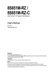
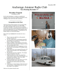
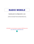
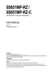
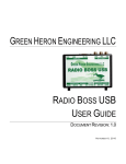
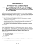
Microwave WebSDR User Guide Index 1. Overview 2. WEB SDR user interface 3. Frequency bands 4. The different types of signals you may hear 5. Decoding telemetry and other received data 6. Technical Data 7. References SUWS Microwave WebSDR User Guide - V1.1 – M.Ehrenfried – G8JNJ – 08/09/2014 1. Overview The WebSDR is operated by the Southampton University Wireless Society, in collaboration with Phil M0DNY, Martin G8JNJ and Noel G8GTZ. The web based receiver covers multiple VHF and UHF amateur radio bands, and can be used by anyone anywhere in the world. The WEB SDR can be viewed with most popular Web Browsers. The earlier versions of software used JAVA which limited the ability to use anything other than a browser with JAVA plugin. The most recent version of WEB SDR software also runs HTML5 which means that the SDR can now be used on a variety of additional mobile devices and tablet PC’s. The receiver site is located near the town of Farnham in the South Eastern part of the United Kingdom at Latitude: 51.23, Longitude: -0.82 2. WEB SDR user interface The main WEB SDR page is divided into a number of functional areas 1. User name or Callsign entry. When using the WEB SDR please type your name or Callsign in to this box. It will identify you on the frequency plan and in the Chat facility if you post a comment. 2. Select the waterfall view you require. Displaying multiple waterfall views is useful if you want to watch the general activity level on all the bands, but this may slow down the display and limit the number of simultaneous viewers who are able to use the SDR at any time. If you intend to monitor just one frequency for a long period of time, please consider selecting the ‘Blind’ option, which disables the scrolling waterfall display and maximises the performance of audio streaming. 3. Ticking the ‘Allow Keyboard’ option permits you to use single keystroke commands such as those shown below. This may be preferable if you don’t wish to use a mouse or touch screen to navigate through the most common command sequences. j k ← →: freq down/up (+shift/ctrl/alt faster) u l c a f: USB, LSB, CW, AM, FM z Z: centre/zoom waterfall g: enter frequency 4. Clicking on the appropriate ‘Radio Button’ allows the manual selection of JAVA or HTML5 operation of the waterfall display and steamed audio. Normally the most suitable selection will be made automatically by your browser, but when an Apple tablet is detected a further option for iOS Audio will appear. 5. The waterfall display shows the reception of active radio signals as a series of scrolling vertical lines. It is possible to move the centre of the waterfall without retuning by left clicking and dragging the mouse left or right on the waterfall display. You can zoom into a specific portion of the waterfall by clicking and using the scroll wheel. 6. The frequency display under the waterfall shows the range of frequencies being received and the yellow marker under the frequency scale shows the current frequency that is being monitored. Left clicking and dragging the mouse left or right just below the frequency scale will retune the SDR Left clicking and dragging the mouse left or right on the edges of the yellow tuning marker will change the bandwidth of the receiver. 7. Band and frequency selection, this allows specific bands and frequencies to be chosen for the reception of signals. Values can be entered numerically or by clicking on the various arrow head keys buttons. The band buttons allow a quick selection of the required frequency range without having to type in frequency values. 8. The memory buttons allow you to Recall, Erase and Store your own specific frequencies which can be used again the next time you log into the SDR, providing that you have entered a name or Callsign in the text entry box at the top of the page. 9. Receiver Mode and Bandwidth, The WEB SDR is capable of receiving many different types of transmissions which may use various modulation schemes. Choosing the correct type of modulation and a suitable reception bandwidth is key to obtaining the best results. This subject will be covered in more detail later in this guide. 10. The Waterfall view controls allow you to define the best type of display for the type of use you are making of the WEB SDR. The Zoom out, Zoom in, Max out and Max in buttons allow you to quickly change the range of frequencies you can see in the waterfall display. Clicking on Max out will show you the whole of a frequency band, and Max in will zoom into frequencies just around the one you are tuned to. This is useful if you want to identify very weak signals or wish to set the receiver bandwidth to match that of the transmitted signal. The speed, size and type of waterfall can also be modified to help spot wanted signals, simply by selecting one of the options in the drop down entry boxes. Selecting ‘Spectrum’ in the view box changes the waterfall so that it looks more like a conventional spectrum analyser display with the amplitude of signals being plotted on the vertical axis, against frequency on the horizontal axis. This can be useful if you wish to compare the relative strength of received signals. The ‘Hide labels’ tick box simply clears the orange marker tags from the frequency display if they are not required, or are cluttering the overall display. 11. Signal strength meter. This provides a bargraph display of the received signal strength. A digital representation of the received signal strength is also shown in dB values just below the bar graph. These figures are useful if you wish to make accurate comparisons of received signal strength between different stations or when using different antennas. 12. The three buttons below the signal strength display allow users to temporarily ‘Mute’ (turn off) the receive audio, apply ‘Squelch’ to mute the audio when no signal is being received, or to select ‘Auto notch’ to remove unwanted whistling carriers or Morse signals when using USB or LSB for reception. The overall volume control can be found at the bottom of this section. 13. Pressing the Audio Recording ‘Start’ button will initiate a recording of the signals you are hearing. This can be ended by pressing the ‘Stop’ button and you will then be given the option to download the recording to your own PC. The title of the recording indicates the date, time, mode and frequency that was present when the recording was started. This is very useful if you want to record a satellite pass so that you can decode the received data some time later. 14. The ‘Signal Strength Plot’ function is also useful if you wish to see the variation in strength of received signals over a period of time. It is possible to select long or short duration plots which can be useful when observing the variation of signals from satellites or propagation beacons. 15. The logbook section allows you to make a note of any special or unusual signals you may have heard. The logbook can be recalled whenever you next use the WEB SDR along with any other entries that others may have made. 16. The display showing multiple frequency bands is a useful way of seeing what other users are using the SDR for and where any interesting activity is occurring. Good examples of this include balloon and satellite tracking when it is possible to see many users on just one or two specific frequencies. 17. The ‘Chatbox’ facility is a quick way of exchanging messages with other users, especially if a special event or rare station is being heard. If you wish to use the Chatbox, please make sure you have entered your name or callsign at the top of the WEB SDR page, so that everyone else knows who they are talking to. It’s also good just to say hello from time to time, especially if new users are logged in. 18. ‘Chatbox’ text entry area. Just type your message in here and press enter. But please don’t leave offensive or insulting messages. The purpose of this SDR is to encourage casual users and people interested in radio and associated technologies to participate so don’t do anything to discourage them. 19. The statistics box shows how many people are currently using the SDR and how much CPU and network bandwidth is being consumed in the process. 20. This box shows the software version number and author’s contact details. 3. Frequency bands The hardware we are using for the WEB SDR to receive signals limits the range of frequencies in each band to a maximum tuning range of 2MHz. For this reason we have had to limit or split the frequency coverage of individual bands in order to provide the best coverage of specific frequency ranges or popular allocations. Because the SDR receive site is very close to 7 other transmitter masts in the immediate vicinity, it occasionally experiences problems with interference from very strong transmissions on frequencies outside of the bands covered by the SDR. Although we have made reasonable attempts to minimise this as much as possible, it is not possible to completely eradicate unwanted signals. Also note that some sections of the Amateur frequency bands covered by this SDR (particularly on 70cm) are shared with the primary (Government) users who may be occasionally heard operating on odd spot frequencies. The bands we have chosen to receive with the WEB SDR include the following:- 3cm 10.368 GHz - 10.370 GHz - Part of the Amateur 3cm Band - Amateur radio propagation beacons and narrow band modes such as SSB & CW (Morse). Signals on this band can normally only be heard over distances of a few 10’s of Km. However when it is raining, or there are other enhancements in radio propagation due to changes in weather conditions, it may be possible to hear signals from much further away. The receiver uses an Octagon PLL LNB satellite down convertor and has the correct frequency labels on the scale (rather than the RTL dongle tuning range). The Octagon does drift up to 30 KHz high with temperature which is not bad considering it is unmodified and mounted on the mast. You can obtain an accurate frequency calibration from the GB3SEE Amateur radio propagation beacon which is visible at all times on 10368.850, and the GB3CCX and GB3LEX beacons which are audible from time to time especially during periods of Rain Scatter and Tropospheric ducting. Signals that are scattered by raindrops have a particularly ‘raspy’ sound to them, and it is often quite difficult to understand or decode signals that are being received in this way. 3cm Narrowband modes 3cm Propagation beacons GB3SEE (visible at all times) 23cm o 10368.000-10368.750 10368.750-10369.000 10368.850 1296-1297MHz - Part of the Amateur 23cm Band - Amateur radio propagation beacons and narrow band modes such as SSB & CW (Morse). The GB3FN Amateur propagation beacon is very loud at all times and GB3MHL / GB3DUN are audible with any improvement in conditions such as aircraft scatter (Heathrow lies directly on the path to MHL). 23cm Narrowband modes & beacons 23cm FM repeaters & simplex 1296.000-1297.000 1297.000-1298.000 437 o 436 MHz - 438 MHz - Part of the Amateur 70cm Band - Amateur radio satellites and Digital Television. Downlinks from orbiting Amateur radio satellites can be heard throughout this band, but they are usually centered on 437.5MHz. o 434 MHz - 436 MHz - Part of the Amateur 70cm Band - Amateur radio satellites and High Altitude Balloon (HAB) telemetry which makes use of short range licence free radio devices, which also share these frequencies and can be seen operating between 434.0 and 434.8MHz o 432 MHz - 434 MHz - Part of the Amateur 70cm Band - Amateur radio narrow band modes, FM repeaters & simplex activity and short range licence free radio devices which also share these frequencies, and can be seen operating between 433.7 and 434.0MHz 435 433 Note that the GB3FN Amateur repeater station is based less than a mile away and is a very strong signal when it is transmitting. We have added an additional notch filter to reduce the severity of this problem, but it still causes occasional interference under certain conditions. 70cm SSB, CW & Propagation beacons 70cm FM repeater outputs 70cm FM Simplex Short range radio devices common frequency (Licence free) High Altitude Balloon tracking telemetry RTTY and SRD's FO-29 (JAS-2) (linear transponder downlink) CubeSat beacons (40+ operational) DATV 432.000-433.000 433.000-433.400 433.400-434.800 434.900 434.000-434.800 435.900-435.800 436.800 - 437.700 437.000 2m o 144 MHz - 146 MHz - Part of the Amateur 2m Band - Amateur radio narrow band modes, FM repeaters & simplex activity, Satellites and the International Space Station. Note that when the SDR first starts up you will be listening to bursts of Packet Data using the FM reception mode on the default frequency of 144.800MHz. 2m SSB & CW GB3VHF 2m Propagation beacon ATV Talkback APRS Packet European common frequency 2m FM simplex calling channel 2m repeater outputs International Space Station FM Voice and SSTV International Space Station Packet Digipeater FunCube-2 (linear transponder downlink) AO-73 (FUNCube-1) (linear transponder downlink) AO-7 (Phase-2B) (linear transponder downlink) 3cm Narrowband modes 10368.000-10368.750 3cm Propagation beacons 10368.750-10369.000 GB3SEE (visible at all times) 10368.850 144.000-144.400 144.430 144.750 144.800 145.500 145.600-145.7875 145.800 145.825 145.930 – 145.950 145.950 – 145.970 145.975-145.925 Further detailed information regarding the Amateur radio allocations in each of the frequency bands can be found at:http://www.thersgb.org/services/bandplans/#19 http://www.thersgb.org/services/bandplans/#20 http://www.thersgb.org/services/bandplans/#21 http://www.thersgb.org/services/bandplans/#25 Or alternatively select the appropriate band on this web page. http://thersgb.org/services/bandplans/html/rsgb_band_plan_jan_2014-1.htm 4. The different types of signals you may hear There are many different types of signals you will see and hear whilst using the WEB SDR. It may take some time before you can identify each type and be able to understand how to extract information from the signal you are receiving. But hopefully these notes will help you along the way. The best starting point may be to look at any signal you are receiving in the waterfall display. The type of signal can usually be identified by zooming in on the vertical trace so that you can more clearly see the way in which the signal is being modulated in order to convey information. If the signal is fairly constant thin line, which varies in width with a slightly irregular pattern, the chances are it will be a voice transmission using either AM or FM. If you choose either of these modes, you will see a yellow outlined shape with sloping edges and a vertical centre line, just underneath the frequency display. The vertical centre line should be dragged to the centre of the signal you are attempting to receive and each of the sloping edges of the yellow outline should be dragged so that the whole of the received signal is just contained within the area defined by the yellow outline. For the best results, try to place both sloping edges of the yellow outline to be symmetrical about the vertical centre line. By doing this you will have ensured that you are tuned to exactly the centre frequency, and have matched the bandwidth to that of the transmitted signal, in order to obtain the best possible reception. Use the volume control to set the audio level to suit your listening conditions. If the audio sounds distorted try selecting a different mode, or slightly retune the receiver centre frequency or bandwidth settings. Most of the time you are likely to hear speech, but some frequencies only carry bursts of data which may need a special decoder to recover information from the transmission. If the signal looks like a very thin line which breaks up as the signal varies in strength, then you may be monitoring a CW (Morse), Single Sideband Voice (USB or LSB) or data transmission. Many of these signals do not transmit a constant reference carrier signal (or in the case of Morse the carrier may be switched on and off to send the message). In order to make sense of these signals we have to inject our own reference signal in order to be able to recover any meaningful information. This can be done by selecting the Upper (USB) or Lower LSB) Sideband modes on the SDR. Most signals in on the VHF and UHF bands require USB, but there are very occasional exceptions. In order to receive signals using USB you have to set the receive frequency very carefully. If you look at the yellow outlined shape with sloping edges and a vertical centre line, just underneath the frequency display, you will notice that when USB or LSB is selected it has an asymmetrical shape to it. The vertical line shows the frequency at which the locally generated reference signal (Local Oscillator) has been injected and the outlined area (to the left for LSB and to the right for USB) shows where the received signal has to be positioned in order to be able to recover the information being conveyed by the transmission. CW (Morse) Transmission USB (Single Side Band SSB) Transmission For CW (on / off Morse) and data transmissions the signal should be placed inside the yellow outlined box. For USB voice transmissions the signal will look fairly wide and this should also be positioned within the yellow outlined box. You may find that you need to make very small adjustments to the received frequency in order to get the correct pitch of voice before you can understand what is being said. When receiving beacon and data signals from orbiting satellites using USB, you may need to keep on retuning as the Doppler shift present on received signals can quickly move outside the bandwidth of the receiver. 5. Decoding telemetry and other data Some transmissions only carry data signals, which may require additional equipment or software to decode. Fortunately many of the more common types of data transmission can be decoded by using your PC soundcard and some free software. Before you can do this you first need to find a way of getting signals received from the WEB SDR into your soundcard. There are three common ways to do this. 1. Make a three way audio splitter lead so that the sound card loudspeaker output can be connected to your external loudspeaker and the soundcard line input at the same time. 2. Use the mixer option that can be found on some soundcards to feed the soundcard audio output back into the line input. 3. Use some virtual audio software to create new virtual audio ports that you can cross connect and select various sound sources and devices to each other without using external patch leads. Examples of such software include ‘Virtual Audio Cable’ http://www.tomsguide.com/us/download/Virtual-Audio-Cable,0305-31100.html and ‘Jack’ Audio connection kit http://jackaudio.org/ Once you have managed to get audio from the SDR fed back into your PC, you can use free software such as the following to decode the signals you can hear. dl-fldigi - http://ukhas.org.uk/projects:dl-fldigi Can be used to decode telemetry signals from high altitude balloons, Morse beacons, slow scan television and much more. Note that if you are uploading data from the balloons you are tracking; please make sure you set your Latitude to 51.23 and Longitude to -0.82 which is the location of the WEB SDR receiver site. For the International Space Station (ISS) Dire Wolf - https://home.comcast.net/~wb2osz/site/ Is a soundcard AX25 packet modem which can be used in conjunction with APRSISCE/32 - http://aprsisce.wikidot.com/ to decode Amateur AX25 packet data and APRS position reporting information that can be heard on 144.800MHz FM or occasionally on 145.825MHz FM when being broadcast from Amateurs on board the International Space Station (if it is in range of the UK). Slow Scan Television is also occasionally transmitted from the ISS on 145.800MHz FM. It can be decoded with software such as MMSTV http://hamsoft.ca/pages/mmsstv.php 6. Technical Software Supplied by Pieter-Tjerk de Boer, PA3FWM, the author of the WebSDR 3cm RF 10GHz Slotted Waveguide Antenna (Horizontal Omni) at 30m AGL Masthead Octagon LNB down converting to 618MHz G8JNJ-modified RTL 820T DVB-T Dongle on 618-620 MHz (10.368 - 10.370 GHz) (Extra Screening) 23cm RF 1296MHz ADM Slot Antenna (Horizontal Omni) at 30m AGL SPF Masthead Pre-Amp G8JNJ-modified RTL 820T DVB-T Dongle on 1295.6-1297.6 MHz (Extra Screening and TCXO) 70cm RF 434MHz Helix Dipole at 30m AGL HABamp with 20dB LNA and 430-437MHz SAW Filter Notch filter for GB3FN Amateur repeater at 433.375MHz 3 x G8JNJ-modified RTL 820T DVB-T Dongles on 432-434 / 434-436 / 436-438 MHz (Extra Screening and TCXO) 2m RF 144Mhz Helix Dipole at 30m AGL HABamp with 20dB LNA and 144-146MHz SAW Filter G8JNJ-modified RTL 820T DVB-T Dongle on 144-146 MHz (Extra Screening and TCXO) All the dongles mounted inside a screened metal box, which provides additional physical protection, screening and thermal stability. Antennas 10GHz Slotted Waveguide Antenna (Horizontal Omni) at 30m AGL 1296MHz ADM Slot Antenna (Horizontal Omni) at 30m AGL 434MHz Helix Dipole at 30m AGL 144Mhz Helix Dipole at 30m AGL More details relating to the helical antennas can be found at:http://g8jnj.webs.com/currentprojects.htm 7. References Useful Web links WEBSDR DC - 30MHz http://websdr.ewi.utwente.nl:8901/ Amateur bandplans http://thersgb.org/services/bandplans/html/rsgb_band_plan_jan_2014-1.htm List of uWave beacons http://www.microwavers.org/indexb.htm UK repeaters http://www.ukrepeater.net/index.html AMSAT UK http://amsat-uk.org/ Amateur sat freqs http://www.dk3wn.info/p/?page_id=29535 On line sat tracker http://www.n2yo.com/ Funcube Website http://funcube.org.uk/ ISS Fan Club http://www.issfanclub.com/ Balloon tracker http://spacenear.us/tracker/ UK High Altitude Soc http://ukhas.org.uk/start UKHAS Google forum https://groups.google.com/forum/#!forum/ukhas UKHAS IRC Chat http://webchat.freenode.net/?channels=highaltitude Software (mostly free) Orbitron stat tracker http://www.stoff.pl/ Fl-digi balloon telemetry http://ukhas.org.uk/projects:dl-fldigi SSTV decoder http://hamsoft.ca/pages/mmsstv.php Soundcard Packet Modem https://home.comcast.net/~wb2osz/site/ APRS client for windows http://aprsisce.wikidot.com/ RTL Dongle Install http://www.rtlsdr.org/softwarewindows SDR Sharp http://sdrsharp.com/ SDR Sharp plugins http://sdrsharp.com/#plugins £7.00 RTL820 SDR dongle https://www.cosycave.co.uk