1
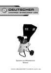
Mil26 Quicktest 2
User Guide
Revision 1.00
Copyright ©, All Rights Reserved,
Phil Ade Services Limited 2004, 2013
Table of Contents:Introduction to the Mil26 Quicktest 2
3
Mil26 Quicktest 2 Functions
4
Testing Cables, Breakout Boxes etc
5
Remote Testing of Cable Installations
7
Maintenance of the Mil26 Quicktest 2
8
Limited Warranty
14
Introduction to the Mil26 Quicktest 2
The Mil26 Quicktest 2 is designed to test Mil26 (BBC Type 7
standard audio multiway) cables, breakout boxes and flails (via
adapters) as quickly as possible. It will detect continuity, phase
reversals, shorts and high resistance across pins caused by
corrosion or water.
The user selects a pair from 1 to 8 on the rotary switch on the box,
where the send end (the Mil26 female end) will send out volts on
the hot, cold and screen pins respectively at approximately once
per second. The current pin under test is indicated by the LED lit
on the hot, cold and screen LEDs.
The detector end (the end with lots of LEDs on it labelled 1 to 8)
will show the user what is present on that cable. If it’s a good
cable then the LEDs on the selected pair should follow the LEDs
indicated at the send end of the Mil26 QuickTest which will be
explained in more detail in the Testing Cables, Breakout Boxes,
etc section of the User Guide.
The BNC connectors on the Mil26 Quicktest 2 are used as a
ground reference for testing cable installations using any of the
following combinations:- 2 x Mil26 Quicktest 2s
- A Mil26 Quicktest (discontinued) and a Mil26 Quicktest 2
- A Mil26 Quicktest 2 and a Mil26 Quicktest Remote
(discontinued)
Mil26 Quicktest 2 Functions
The overall operation of the Mil26 Quicktest 2 is explained in the
photo below:-
Sender End
LEDs status
Sender Pair
Selection and
On/Off Switch
Detector
End
Connector
Detector
LEDs Status
Sender End
Connector
Battery
Compartment
Ground
Referfence
Connector
Testing Cables, Breakout Boxes, etc
To test a cable (end to end), just simply connect both ends of the
box together with that cable. Rotate the rotary switch from position
0 (off) to position ‘1’. The LEDs on the sender end should now
light up in sequence (hot, cold and screen respectively). The
LEDs (under the number ‘1’, which means ‘Pair 1’) on the detector
end of the Mil26 Quicktest 2 should now follow the LEDs on the
sender end of the Mil26 Quicktest 2. Repeat this for pairs 2 to 8.
NOTE: Pair 8 of the Mil26 Quicktest 2 has been wired pins ‘R’, ‘S’
and ‘a’ respectively.
Whilst the cable is being tested, the user should wiggle the cable
ends to check to see if that cable happens to be intermittent.
If the cable has a fault on it for any reason, the following below
may give a clue to what fault is present on that cable:- LEDs light up in reverse order (e.g. green, yellow then
red)
- Pair is out of phase.
- One of the LEDs does not light up during the sequence.
- One of the wires is open circuit.
- More then one LED is lit at the same time.
- Short circuit or high resistance (caused by corrosion
or water) across more than one pin of the Mil26
connector(s)
- One or more of the LEDs flash on and off as the user
wiggles the cable.
- The cable is intermittent and may fail.
To test a breakout box or a flail the user would use a similar
method via adapters or Mil26 to XLR flails in the case of testing a
Mil26 breakout box.
XLR looms can also be tested by using Mil26 to XLR flails by using
the method outlined in the above.
Do not forget to rotate the rotary switch of the Mil 26
Quicktest 2 to “0” (OFF) after use. The LEDs on the sender end
will go out after the user has switched the Mil 26 Quicktest 2 unit
off.
Remote Testing of Cable Installations
To test a remote cable installation (such as a permanent rig for
example), the user could use any of the following combinations:- Two Mil26 Quicktest 2 units
- A Mil26 Quicktest 2 unit and a Mil26 Quicktest unit
- A ground reference connection next to the Mil 26
connectors at both ends. This could be in any form such
as a BNC video connector or a triax end via a BNC to triax
adapter. DO NOT CONNECT THIS TO A MAINS EARTH!
To perform a remote cable test, connect the Mil26 Quicktest 2 to
the termination panel from where the permanent rig starts. Two
people are needed to perform this test and it would be a good idea
to have some form of communication whilst carrying out this test.
Connect both the Mil 26 female (it may be a good idea to have a
very short length of multiway and video cable at this point) and the
BNC connector at the send end to the termination panel from
where the permanent rig starts. One person should stay at that
point to change the pair selection for the duration of the test.
At the remote end, connect both the Mil 26 male and the BNC as
described in the above paragraph to the termination panel at the
remote end. The other person should stay at that position and
watch the LEDs at the remote end and communicate back to the
person at the other end.
Switch on both Mil 26 Quicktest 2/Mil 26 Quicktest units to start
this test.
The overall procedure of detecting faults is exactly the same as the
Testing Cables, Breakout Boxes, etc section.
Do not forget to switch both boxes off after use !
Maintenance of the Mil 26 Quicktest 2
General maintenance of the Mil 26 Quicktest 2 is pretty
straightforward. The PCBs on the Mil 26 Quicktest 2 are
connected via IDC Box Connectors to make maintenance as
simple as possible.
To remove the Mil 26 connectors (if they get bent for any reason),
just simply undo the four self-tapper screw on the top of the lid and
undo the IDC box connectors from the PCBs. Now undo the three
bolts on the bottom of the Mil 26 QuickTest to remove the PCBs
and the Mil 26 connectors are easily accessible.
The pinouts for the Mil 26 connectors are given below (note the
red stripe is pin 1):BBC Type 7 (Mil26 Female)
Near End
26 Way Box
Connector
IDC 1/10 " Pitch Pin #
1
2
3
4
5
6
7
8
9
10
11
12
13
14
15
16
17
18
19
20
21
22
23
24
Mil 26
Female
Pin #
Purpose
A
B
T
C
D
U
E
F
V
G
H
W
J
K
X
L
M
Y
N
P
Z
R
S
a
Pair 1 Hot
Pair 1 Cold
Pair 1 Screen
Pair 2 Hot
Pair 2 Cold
Pair 2 Screen
Pair 3 Hot
Pair 3 Cold
Pair 3 Screen
Pair 4 Hot
Pair 4 Cold
Pair 4 Screen
Pair 5 Hot
Pair 5 Cold
Pair 5 Screen
Pair 6 Hot
Pair 6 Cold
Pair 6 Screen
Pair 7 Hot
Pair 7 Cold
Pair 7 Screen
Pair 8 Hot
Pair 8 Cold
Pair 8 Screen
BBC Type 7 (Mil26 Male)
Far End
26 Way Box Connector
IDC 1/10 " Pitch Pin #
3
4
5
6
7
8
9
10
11
12
13
14
15
16
17
18
19
20
21
22
23
24
25
26
Mil 26 Female
Pin #
Purpose
S
a
Z
R
N
P
M
Y
X
L
J
K
H
W
V
G
E
F
D
U
T
C
A
B
Pair 8 Cold
Pair 8 Screen
Pair 7 Screen
Pair 8 Hot
Pair 7 Hot
Pair 7 Cold
Pair 6 Cold
Pair 6 Screen
Pair 5 Screen
Pair 6 Hot
Pair 5 Hot
Pair 5 Cold
Pair 4 Cold
Pair 4 Screen
Pair 3 Screen
Pair 4 Hot
Pair 3 Hot
Pair 3 Cold
Pair 2 Cold
Pair 2 Screen
Pair 1 Screen
Pair 2 Hot
Pair 1 Hot
Pair 1 Cold
To remove any of the LEDs from the Mil 26 Quicktest 2 (in case
any get broken), just simply remove the lid and disconnect the
LEDs ribbon cable from the detector PCB (the top one). Unsolder
the + end of the LED from the bus bar and unsolder the – end from
the wire. The pinout for the LEDs is also give below:Detector
LEDs
26 Way Box Connector
IDC 1/10 " Pitch Pin #
1
3
4
5
6
7
8
9
10
11
12
13
14
15
16
17
18
19
20
21
22
23
24
25
26
Purpose
Pair 1 Hot
Pair 1 Screen
Pair 1 Cold
Pair 2 Cold
Pair 2 Hot
Pair 3 Hot
Pair 2 Screen
Pair 3 Screen
Pair 3 Cold
Pair 4 Cold
Pair 4 Hot
Pair 5 Hot
Pair 4 Screen
Pair 5 Screen
Pair 5 Cold
Pair 6 Cold
Pair 6 Hot
Pair 7 Hot
Pair 6 Screen
Pair 7 Screen
Pair 7 Cold
Pair 8 Cold
Pair 8 Hot
+ 9V LEDs
Pair 8 Screen
Replacing the rotary switch is fairly difficult. A lot of diodes have
been soldered onto this switch to provide a binary code for the
electronics inside the Mil 26 Quicktest 2 (since there are no BCD
encoders available any more) as well as an On/Off switch.
To remove the switch, remove the lid and remove the 10 pin Box
Connector from the sender PCB (the bottom one) and remove the
switch.
Whilst replacing the rotary switch, make sure that the diodes and
the wires from the ribbon cable on the new switch are soldered in
exactly the same order as they came out. Failure to do this will
result in the binary code for the electronics being incorrect and will
cause the wrong pair of the Mil26 Quicktest 2’s sender being
selected as a result. It may also prevent the Mil26 Quicktest 2
from powering up.
The pinout for the rotary switch is given below:Rotary Switch
and LEDs
10 Way Box
Connector
IDC 1/10 " Pitch Pin
#
3
4
5
6
7
8
9
10
Purpose
Logic 0 – Rotary Switch
C (4) – Rotary Switch
A (1) – Rotary Switch
B (2) – Rotary Switch
Hot LED
Cold LED
Screen LED
+9V Switch (not
used - +9V is
now wired to the
centre pin of the
rotary switch)
Limited Warranty
The Mil 26 Quicktest 2 has a limited warranty of 12 months from
the date of invoice (per unit). Exclusions of the warranty include
the following:- Immersion in a liquid
- Damage caused by plugging the box into RTS, Phantom
Power, Mains etc.
- Damage caused by dropping the Mil 26 Quicktest 2.
-
Damage caused by excessive force used to connect
damaged cable ends.
- Using a leaking 9V battery inside the unit.
-
Damage caused by using batteries other than 9V PP3
batteries to operate the Mil 26 Quicktest 2.