1
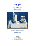
COMPLETE FILTRATION SYSTEMS SYSTEM 2500/5000 FRESHWATER USER GUIDE Tropical Marine Centre Solesbridge Lane Chorleywood WD3 5SX United Kingdom Tel: +44 (0) 1923 284151 Fax: +44 (0) 1923 285840 Email: [email protected] Website: www.tropicalmarinecentre.co.uk TMC COMMERCIAL SYSTEM 2500/5000 FRESHWATER USER GUIDE Contents SECTION PAGE Contents ...................................................................................................................... 1 A. Installation Instructions ......................................................................................... 2 General Layout Schematic ........................................................................................... 6 B. Operating Instructions ........................................................................................... 7 C. Maintenance Instructions ..................................................................................... 11 Daily Maintenance .................................................................................................... 11 Weekly Maintenance ................................................................................................. 11 Monthly Maintenance ................................................................................................ 11 Biannual Maintenance ............................................................................................... 11 Optimal Values for Water Quality Parameters ..................... Error! Bookmark not defined. D. Commercial Ultraviolet Water Steriliser .................................................................. 14 Instructions For Installation And Use ........................................................................... 14 Connection To Electrical Supply .................................................................................. 15 E. Ultraviolet Water Steriliser Maintenance Procedure .................................................. 16 IMPORTANT: ............................................................................................................ 18 VERSION 22/03/2013 PAGE 1 A. Installation Instructions 1. Unpack the contents carefully, taking particular caution when handling any of the clear acrylic components, which are more easily broken. 2. No specialist tools are required to assemble the filtration unit. 3. Locate the reservoir in its desired final location (the system can be moved Figure i (Viewed from the back) retrospectively with the aid of a pallet truck). The shorter sides of the reservoir are the front and back of the system. 4. Place the filter bag housing at one of the shorter ends as shown in figure i. The profile of the bag filter matches the profile of the bin, so it’ll easily slot into place. 5. Insert the black rubber flange into the circular hole at the top of the narrow end of the filter bag housing. 6. Place the support stanchion inside the tank with the spigot facing upwards. 7. Place the support grid on top of the reservoir so that the large cut-out section is at the back with the smaller cut-out section is on the right hand side, as shown in figure ii. 8. Adjust the stanchion so position that it of is the support approximately 200mm from the front of the bag filter and Figure ii (Viewed from the back) TMC COMMERCIAL SYSTEM 2500/5000 FRESHWATER USER GUIDE so it sits between the TBT and In-Line media reactor. 9. Place the remaining components on the platform, positioning them according to the General Layout Schematic (page 7). Pay close attention and to the orientation direction of the inlet and outlet bosses. IMPORTANT: Do not add any media to the fluidised sand tower (FST) at this stage. 10. Ensure that the clear plastic media in the trickle bio tower (TBT) is clear of the spray bar mechanism and that the bar can rotate freely. Figure iii 11. The units are now ready to be connected together with the pre-assembled plumbing provided. Begin assembly with the connection of the intake strainer assembly to the filtration system pump inlet. Proceed with other connections following the alphabetical labelling; i.e. A to A, B to B and so on. place before Ensure all o-rings are in making each connection, removing and retaining tape first. Once all the plumbing is fully assembled, handtighten all the unions (threaded couplings). IMPORTANT: Do not grease or wet any of the o-rings in the connection bosses of the components. Figure iv 12. Ensure that the flow meter (if included) is VERSION 22/03/2013 PAGE 3 TMC COMMERCIAL SYSTEM 2500/5000 FRESHWATER USER GUIDE correctly assembled with the float and stabilising vane in the right direction. Ensure that all outer packaging has been removed. 13. Avoid putting any of the joins under stress when connecting components. All filtration units are assembled and then disassembled prior to dispatch ensuring correct fitting. If you encounter any difficulty or resistance fitting components together attempt to realign them 14. The following fittings, connection and components are not included as standard, but can be ordered separately: Return supply pump and fittings to connect to the UV and onto your aquariums. Return pipe work and fittings from your aquariums returning to the bag filter. Elecro heaters which can run from the purge on the filtration pump. UV Bypass which allows you to keep your supply pump running while doing maintenance to your UV. 20kg sacks of HR carbon for the In-Line media reactor. Spare/replacement filter bags for your bag filter and In-Line media reactor. Figure v 15. Suitable electrical cable should be used to wire the pumps, UV steriliser and any additional electrical VERSION 22/03/2013 equipment supplied PAGE 4 TMC COMMERCIAL SYSTEM 2500/5000 FRESHWATER USER GUIDE with the unit. All electrical equipment is provided for connection to single-phase supply, unless specified otherwise. If in doubt, consult a qualified electrician. CAUTION: Installation must comply with the relevant local wiring guidelines and legislation. Please consult a qualified electrician. CAUTION: Always disconnect the UV steriliser from the mains electricity supply before putting your hands into the water. CAUTION: Power must be supplied through a Residual Current Device (RCD) with a rated residual operating current no exceeding 30 mA. A switch with a minimum 3 mm contact separation must be provided in the fixed wiring to isolate any electrical devices from the mains electricity supply. INTERNAL FUSE REPLACEMENT: Always isolate from mains supply before undertaking any maintenance. Only use a suitably rated fuse. IMPORTANT: Do not add any sand to the fluidised sand tower (FST) until you are satisfied that the unit is operating without any visible leads from the components or joints 16. The filtration unit, once assembled according to the instructions, is ready to be filled with water. To test the filtration pump and system, no further connections are necessary. The unit does not need any other connection to be made to enable it to operate. Follow the operating instructions carefully. VERSION 22/03/2013 PAGE 5 TMC COMMERCIAL SYSTEM 2500/5000 FRESHWATER USER GUIDE General Layout Schematic Plan view of the approximate positions of components supplied with the SYSTEM 2500/5000 Freshwater. Pay close attention to the orientation and direction of the inlet and outlet bosses. VERSION 22/03/2013 PAGE 6 TMC COMMERCIAL SYSTEM 2500/5000 FRESHWATER USER GUIDE B. Operating Instructions 1. Before commissioning the system, we recommend running without livestock, using a saltwater mix containing at least 100 kg of PVD salt for 24 hours. This will help to ‘cure’ all plastic surfaces and remove any traces of oils used in the manufacture of the plastic components, filter media and plumbing. It is also beneficial to increase the temperature of the water to approximately 25°C to aid the dissolving and efficiency of the salt. If you are curing any of the adjoining plumbing and system in the same manner please ensure that the UV unit is bypassed to prevent salt deposition on the quartz sleeves. 2. Before starting any pumps, fill pump strainer basket chamber and make certain that the reservoir is full of water and that all connections are watertight. IMPORTANT: Read the following operating instructions carefully before switching on any pumps. Do not switch on the UV steriliser. 3. Close all valves with the exception of the following which should be fully open: Ball Valve No. 1: Valve on system bypass to the reservoir Ball Valve No. 2: Valve to The Trickle Bio Tower Ball Valve No. 3: Valve to the bypass below the In-Line Media Reactor 4. Start the filtration system pump, allowing it to prime and clear air from line. All water should pass through the fully opened bypass (ball valve no. 1), returning directly to the reservoir. 5. Slowly adjust ball valve no. 1 to allow the rest of the system to fill. Avoid filling the system too quickly and overflowing any of the filtration components. VERSION 22/03/2013 PAGE 7 TMC COMMERCIAL 6. SYSTEM 2500/5000 FRESHWATER USER GUIDE Check all joints and unions for leaks, and remove any plastic swarf floating in the reservoir. Place the four filter bags supplied in the location rings in the bag filter box. 7. Drain the water from the system and system elements, flushing again with freshwater and run the system until all components are fully rinsed to remove any residual salt. 8. Thoroughly rinse/wash the sand for the fluid sand tower (FST) before use. 9. With the system turned off, siphon out 50% of the water in the fluid sand tower (FST) prior to adding the sand media. Remove the clear, vent pipe on top of the fluidised sand filter. Use a funnel (not supplied) to carefully add the sand. When all the sand media is added, replace the vent pipe, ensuring it is completely clear of sand and grit. The fluid sand tower (FST) can be detached at the acrylic section as an alternative method of adding the sand. Please handle the acrylic with care, as it is fragile. IMPORTANT: Repeat steps 2 – 4 and then proceed as follows: 10. Very slowly, adjust ball valve no. 1 until the sand media in the fluid sand tower (FST) is fluidised so that the sand level reaches mid-way up the acrylic section. IMPORTANT: Do not adjust any valves completely or too quickly or the sand media may be fluidised to the point of overflowing through the clear vent pipe or overflowing into the other filtration elements. Large amounts of rising trapped air may also cause the sand to overflow if this start up procedure is not carried out carefully. 11. Once the water flow through the fluidised sand bed filter is stabilised adjust valve 2 so you’re getting one VERSION 22/03/2013 PAGE 8 TMC COMMERCIAL SYSTEM 2500/5000 FRESHWATER USER GUIDE rotation per second of the spray bar in the trickle bio tower. 12. One rotation per second is sufficient but may be further reduced to give a suitable dry/wet exposure of the random fill media, depending on application and filtration requirements. IMPORTANT: The arms of the spray bar are not glued to allow the customer to adjust the angle of the spray to further control the speed of rotation for a given flow of water. 13. Adjust valve 3 so you’ve got adequate flow going through the In-Line Media Reactor. 14. Further adjustments may be necessary to fine-tune the flow of water to the main filter elements and this should be done using valves 1, 2 and 3. Once satisfied with the operation and running of the filtration system, the distribution pump may now be switched on for supply to the aquaria via the UV unit. The UV unit should only be switched on when there is water flowing through it. 15. It is recommended that any alterations and modifications made to the system in the due course of normally day-to-day running, be made in the morning. This is because backpressures and flow rates can take up to several hours to equalise and these need to be monitored periodically throughout the day. IMPORTANT: The SYSTEM 2500/5000 like any other biological filtration units, require a maturation period (to allow colonisation of the appropriate levels of nitrifying bacteria) before it can be used on a fully stocked system. 16. The length of the maturation period will vary from 4 – 12 weeks depending on the initial stocking levels, water temperatures, feed rates and other criteria. Throughout this period, ammonia and nitrite should be monitored daily to maturation process. VERSION 22/03/2013 assess the progress of the Further stocking should only be PAGE 9 TMC COMMERCIAL SYSTEM 2500/5000 FRESHWATER USER GUIDE considered once the system is fully matured. 17. When reservoir levels are low due to maintenance or high sales, ensure the pumps are not allowed to draw air. It is strongly recommended that systems be fitted with water level switches to ensure that water pumps cannot draw air. Do not allow bubbles from return water to be drawn into the pump inlet. CAUTION: All of these will cause embolism that will kill livestock. 18. All items supplied with this system are covered by warranties under Tropical Marine Centre's standard terms and conditions. However, Tropical Marine Centre Limited cannot be held responsible for any subsequent damage or the loss of livestock caused by the failure of any system component. VERSION 22/03/2013 PAGE 10 TMC COMMERCIAL SYSTEM 2500/5000 FRESHWATER USER GUIDE C. Maintenance Instructions Recommended regular maintenance tasks for the SYSTEM 2500/5000: DAILY MAINTENANCE Check overall system and livestock health for early signs of problems Check bag filters for blockages and wash as necessary. Check rotation of bio-tower spray-bar Check sand bed fluidisation level and adjust accordingly WEEKLY MAINTENANCE Carry out regular water tests with particular reference to pH, ammonia and nitrite when the system is maturing Perform partial water change (generally around 10 %) Check water salinity/density Change bag filters. If new bags are used, rinse in freshwater before installation Carry out a visual check on pump strainer baskets and intake strainers MONTHLY MAINTENANCE Inspect pump, UV steriliser and filter seals. Due to the abrasive nature of the fluidised sand bed filter media, the bowl may need to be replaced periodically and should be inspected for any signs of wear. Replacement bowls are available from TMC (product code FSB/VFCA4G8). BIANNUAL MAINTENANCE Change ultra violet lamps using TMC 55 Watt UV lamps (product code 6056) Clean quartz sleeves (product code 5277) on UV steriliser and replace o-rings (product code 5281) Inspect bio media for mulm build up and clean/replace as necessary Check and clean clear pump lids The system has been designed with as much flexibility as VERSION 22/03/2013 PAGE 11 TMC COMMERCIAL SYSTEM 2500/5000 FRESHWATER USER GUIDE possible. Modifications and expansions are usually very easy to achieve. Please consult Tropical Marine Centre directly with any queries. VERSION 22/03/2013 PAGE 12 TMC COMMERCIAL SYSTEM 2500/5000 FRESHWATER USER GUIDE OPTIMAL VALUES FOR WATER QUALITY PARAMETERS Parameter Freshwater community oc African Freshwater Cichlid Plants & Discus oc 25-30oc 4-30oc Temperature 22-26 pH Value 6.5-7.5 7.8-8.5 6.0-7.5 6.5-7.5 < 0.05 mg/l < 0.05 mg/l < 0.05 mg/l < 0.05 mg/l <0.02 mg/l <0.02 mg/l <0.02 mg/l <0.02 mg/l < 50 mg/l < 50 mg/l < 30mg/l < 50 mg/l 4-8KH 10-18KH 3-8KH 4-8KH 4-12GH 12-20GH 3-8GH 4-12GH Ammonium/Ammonia 22-26 Pond + Total Conc (NH4 /NH3) Nitrite (NO2-) Nitrate (NO3-) Alkalinity(Carbonate Hardness) General Hardness Table 1 Please note that values above are only intended for use as general guidelines. Optimal tank parameters vary according to specific tank conditions and the organisms kept. VERSION 22/03/2013 PAGE 13 TMC COMMERCIAL SYSTEM 2500/5000 FRESHWATER USER GUIDE D. Commercial Ultraviolet Water Steriliser INSTRUCTIONS FOR INSTALLATION AND USE All Tropical Marine Centre Commercial Ultraviolet Water Sterilisers using 55-watt lamps are supplied with two-inch solvent weld unions for easy connection to existing plumbing. We advise that a two-inch bypass system is incorporated into the installation of the UV unit to simplify future servicing and maintenance. The unit is supplied with two-inch solvent-weld socket unions for connection to imperial and US plumbing fittings. Where metric plumbing fittings are to be used an inch to metric adapter can be supplied (2" × 63mm Solvent-Weld Metric Socket Adaptor, part number 7545) IMPORTANT SAFETY INFORMATION: All units must be mounted with the lamps in a horizontal position. Never mount the unit with the lamps in a vertical position. Incorrect mounting and positioning will result in malfunction and permanent damage to the unit. Never look directly at an illuminated UV lamp. Do not operate the unit when disconnected from the water supply or allow the unit to run dry Always isolate the unit from mains electricity and turn off the water supply prior to carrying out maintenance. Always disconnect from mains supply before putting your hands into the water. Electricity should be supplied through a Residual Current Device (RCD) with a rated residual operating current not exceeding 30mA. The unit must be earthed. Do not use a fuse larger than 3 amps. Rating: UK and European models 220 – 240 v 50 Hz. Class 1, IP64. Rating: USA models 120 v 60 Hz. Class 1 IP64. The unit must not be submerged in water. VERSION 22/03/2013 PAGE 14 TMC COMMERCIAL SYSTEM 2500/5000 FRESHWATER USER GUIDE The unit must be fully frost protected or taken inside during the winter months. Do not install it above or immediately alongside exposed water, to prevent the unit falling into it. CONNECTION TO ELECTRICAL SUPPLY If in doubt, consult a qualified electrician. CAUTION: Installation must comply with the relevant local wiring guidelines and legislation. Please consult a qualified electrician. CAUTION: Always disconnect the UV steriliser from the mains electricity supply before putting your hands into the water. CAUTION: Power must be supplied through a Residual Current Device (RCD) with a rated residual operating current no exceeding 30 mA. CAUTION: Power is supplied to the UV lamps via electronic ballasts. The unit should not be installed in any electrical circuit with equipment that may produce an inductive load. This includes equipment such as conventional fluorescent luminaires, floodlights and water pumps. Inductive loads can generate high-energy surges that permanently damage the electronic ballast. Suitable electrical cable should be used to wire the pumps, UV steriliser and any additional electrical equipment supplied with the unit. All electrical equipment is provided for connection to single-phase supply, unless specified otherwise. If in doubt, consult a qualified electrician. A switch with 3 mm contact separation must be provided in the fixed wiring to provide disconnection from the electricity supply. INTERNAL FUSE REPLACEMENT: Always isolate from mains supply before undertaking any maintenance. Only use a suitably rated fuse. VERSION 22/03/2013 PAGE 15 TMC COMMERCIAL SYSTEM 2500/5000 FRESHWATER USER GUIDE E. Ultraviolet Water Steriliser Maintenance Procedure IMPORTANT SAFETY INFORMATION: Please Read Carefully Never look directly at an illuminated UV lamp. Always isolate the unit from mains electricity and turn off the water supply prior to carrying out maintenance. If the quartz sleeve is accidentally cracked it must be replaced prior to reconnection to either the electrical or water supplies. If you do not have a replacement quartz sleeve, remove the broken sleeve and use the blue blanking plugs provided with the unit to close off the ends of the affected tube. HALF-YEARLY MAINTENANCE All maintenance should only be undertaken by trained and competent staff. The UV lamps should be changed at 4000-hour intervals (approximately six month) to achieve a high UV efficiency. Should the lamps only be changed at 8000 hours intervals (approximately annually) there is a 15 % depreciation in UV efficiency over one year. PROCEDURE: 1. Isolate the ultraviolet steriliser from the electrical supply at the control panel. 2. Isolate the ultraviolet steriliser from the water supply by closing any supply valves or opening any installed bypass. 3. Drain the water from the unit by opening the drainage tap (orange bib tap) located on the bottom support bar of the unit. Wall mounted units are not fitted with a drainage tap. 4. Carefully remove the numbered black lamp end cap from the lamp. Repeat this procedure at the opposite end of the same lamp assembly. 5. Carefully slide out each used UV lamp ensuring that no VERSION 22/03/2013 PAGE 16 TMC COMMERCIAL SYSTEM 2500/5000 FRESHWATER USER GUIDE pressure is applied to the quartz sleeve. 6. Unscrew the compression fitting at either end of the lamp assembly. 7. Remove the o-ring at either end of the quartz sleeve assembly. NOTE: If water pours out of the unit at this stage then the unit has either not been isolated from the system or not drained prior to commencing the maintenance procedure. 8. Remove the o-rings and discard them. O-rings should be replaced at each service interval. 9. After removing the o-ring, carefully slide out the quartz sleeve. Clean the quartz sleeve by washing in warm soapy water. Rinse it thoroughly in fresh water, then dry, and polish it using a paper towel. NOTE: If the quartz sleeve has calcified with lime scale deposits from the water it should be cleaned with a proprietary plastic kettle descaling solution, following the manufacturer’s recommendations. Plastic gloves and eye protection should be worn for this process. The quartz sleeve should be rinsed in fresh water, dried and polished with a paper towel. 10. To reassemble the unit reverse the above procedure by carefully sliding the quartz sleeves back into the plastic housing and locating it correctly. Slide new o-rings over either end of the quartz sleeve and locate them into the oring recess on the main casing. 11. Ensure the female threads on the compression fitting and the male threads on the main plastic body are clean. Wipe a little silicon grease or Vaseline (NOT silicon sealant) onto these threads. As these threads are only serviced twice a year, this lubrication will help prevent them binding. Replace and firmly hand tighten the compression fittings. NOTE: The compression fitting must be adequately tightened onto the o-ring and quartz sleeve or the unit will VERSION 22/03/2013 PAGE 17 TMC COMMERCIAL SYSTEM 2500/5000 FRESHWATER USER GUIDE leak water when reconnected to the main system. 12. Once all the quartz sleeves, o-rings and compression fittings have been reassembled, the drainage tap at the base of the unit must be closed and any utility valves be reopened. Check each assembly to ensure there are no water leaks. If water is leaking from any of the assemblies then the unit must be drained down again following the procedure above. At the points where water is leaking, check the quartz sleeves for damaged and check that the o-rings are correctly positioned. Make certain that the compression fittings are fully tightened. 13. Assuming there are no water leaks, slide the new UV lamp into the quartz sleeve and replace the lamp ends. Each end cap has a unique number that refers to each lamp. It is critical that the correct lamp end cap is fitted to the appropriate lamp. 14. Always ensure that water is circulating through the UV steriliser before the lamps are turned back on. 15. Once all the lamps have been connected, the UV steriliser unit should be turned back on at the control panel. Check each lamp to verify that it is working. Only view the lamp through the plastic locknut compression fitting. Never look directly at an exposed UV lamp. IMPORTANT: The plastic body of this unit has been manufactured from polymers specifically stabilised to protect them from the effects of germicidal UVc light emitted from the lamp. Despite the UV protection, the unit will be eroded over time by a combination of the UVc and water flow. As a matter of course, inspect the unit whenever a lamp changes are carried out. Make sure that the unit does not show signs of excessive deterioration. Replacement parts are available from Tropical Marine Centre. VERSION 22/03/2013 PAGE 18