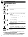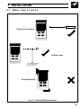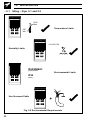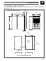
1
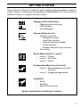
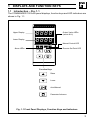
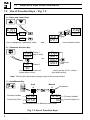
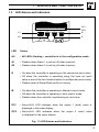
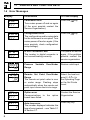
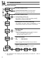
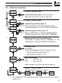
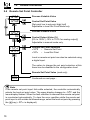
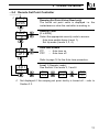
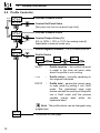
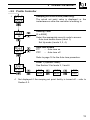
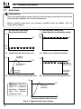
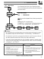
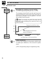
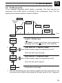
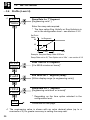
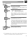
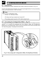
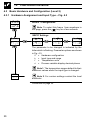
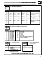
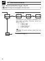
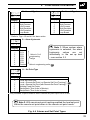
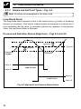
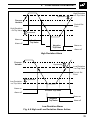
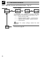
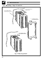
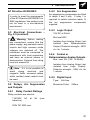
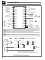
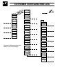
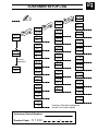
User Guide
COMMANDER 100
Universal Process Controller
48.2
100.0
OP2
OP1
A1
A2
R
COMMANDER
M
100
Use of Instructions
Warning.
An instruction that draws attention to
the risk of injury or death.
Note.
Clarification of an instruction
additional information.
Caution.
An instruction that draws attention to
the risk of damage to the product,
process or surroundings.
Information.
Further reference for more detailed
information or technical details.
or
Although Warning hazards are related to personal injury, and Caution hazards are
associated with equipment or property damage, it must be understood that operation of
damaged equipment could, under certain operational conditions, result in degraded
process system performance leading to personal injury or death. Therefore, comply fully
with all Warning and Caution notices.
Information in this manual is intended only to assist our customers in the efficient operation
of our equipment. Use of this manual for any other purpose is specifically prohibited and
its contents are not to be reproduced in full or part without prior approval of Technical
Communications Department, ABB Instrumentation.
Health and Safety
To ensure that our products are safe and without risk to health, the following points
must be noted:
1. The relevant sections of these instructions must be read carefully
proceeding.
before
2. Warning labels on containers and packages must be observed.
3. Installation, operation, maintenance and servicing must only be carried out by
suitably trained personnel and in accordance with the information given.
4. Normal safety precautions must be taken to avoid the possibility of an accident
occurring when operating in conditions of high pressure and/or temperature.
5. Chemicals must be stored away from heat, protected from temperature extremes
and powders kept dry. Normal safe handling procedures must be used.
6. When disposing of chemicals ensure that no two chemicals are mixed.
Safety advice concerning the use of the equipment described in this manual or any
relevant hazard data sheets (where applicable) may be obtained from the Company
address on the back cover, together with servicing and spares information.
GETTING STARTED
This manual is divided into 5 sections which contain all the information needed to
install, configure, commission and operate the COMMANDER 100. Each section is
identified clearly by a symbol as shown below.
Displays and Function Keys
•
Displays and function keys
•
LED Indication
•
Error Messages
Operator Mode (Level 1)
•
Operator menus for:
– Standard controller
– Heat/Cool controller
– Remote Set Point controller
– Profile controller
– Multiple Fixed Set Points controller
•
Auto tuning
8
Set Up Mode (Levels 2, 3 and 4)
•
Level 2 – Tuning
•
Level 3 – Set Points
•
Level 4 – Profile
Configuration Mode (Levels 5 and 6)
•
Level 5 – Basic hardware and control
functions
•
Level 6 – Ranges and passwords
Installation
•
Siting
•
Mounting
•
Electrical connections
Symbol Identification and Section Contents
1
CONTENTS
1
DISPLAYS AND FUNCTION KEYS ............................................................. 3
1.1 Introduction .......................................................................................... 3
1.2 Use of Function Keys .......................................................................... 4
1.3 LED Alarms and Indicators ................................................................. 5
1.4 Error Messages ................................................................................... 6
2
OPERATOR MODE ...................................................................................... 7
2.1 Introduction .......................................................................................... 7
2.2 Standard Controller ............................................................................. 8
2.3 Heat/Cool Controller ............................................................................ 9
2.4 Remote Set Point Controller ............................................................. 10
2.5 Profile Controller ............................................................................... 12
2.6 Multiple Fixed Set Points Controller ................................................. 14
2.7 Auto-tune ........................................................................................... 16
3
SET
3.1
3.2
3.3
3.4
4
CONFIGURATION MODE .......................................................................... 28
4.1 Introduction ............................................................................................
4.2 Accessing the Configuration Mode ................................................... 28
4.3 Basic Hardware and Configuration (Level 5) ................................... 30
4.4 Ranges and Passwords (Level 6) ..................................................... 40
5
INSTALLATION .......................................................................................... 43
5.1 Siting .................................................................................................. 43
5.2 Mounting ............................................................................................ 45
5.3 Electrical Connections ...................................................................... 47
5.4 Relays, Arc Suppression, Digital Input and Output .......................... 47
UP MODE ............................................................................................ 18
Introduction ........................................................................................ 18
Tuning (Level 2) ................................................................................ 18
Set Points (Level 3) ........................................................................... 22
Profile (Level 4) ................................................................................. 25
Information.
The fold-out page inside on the back cover of this
manual shows all the frames in the programming
levels. Space is provided on the page for writing the
programmed setting or selection for each frame.
2
1
1.1
DISPLAYS AND FUNCTION KEYS
Introduction – Fig. 1.1
The COMMANDER 100 front panel displays, function keys and LED indicators are
shown in Fig. 1.1.
Upper Display
Lower Display
8888
8888
OP1
A1
A2
R
OP2
Output Value LEDs
(secret-til-lit)
Manual Control LED
M
Alarm LEDs
Remote Set Point LED
Function Keys
Raise
Lower
Auto/Manual
Parameter Advance
Fig. 1.1 Front Panel Displays, Function Keys and Indicators
3
…1
1.2
DISPLAYS AND FUNCTION KEYS
Use of Function Keys – Fig. 1.2
A – Raise and Lower Keys
bIAS
50.0
LEV2
tUnE
51.0 +
49.0 –
Use to change/set a parameter value…
and…
LEV1
OPEr
…move between levels
B – Parameter Advance Key
1
LEV2 Frame
(top of level)
tUnE
or…
CYCl Frame 2
5.0
Use to advance to the next
frame within a level…
LEVx
1001
1002
1003
Press and
hold
…select the top (LEVEL) frame
from within a level
Note. This key also stores any changes made in the previous frame
C – Auto/Manual Key
Process Variable
Control Set Point
Auto
Manual
M
M
125.2
125.8
125.2
70
Use to select Auto or Manual control mode
Fig. 1.2 Use of Function Keys
4
Illuminated
Process Variable
Control Output (%)
1
1.3
DISPLAYS AND FUNCTION KEYS…
LED Alarms and Indicators
OP1
A1
A2
R
OP2
OP1
OP2
M
A1
M
A2
R
LED
Status
All
• All LED's flashing – controller is in the configuration mode.
A1
• Flashes when Alarm 1 is active (off when inactive).
A2
• Flashes when Alarm 2 is active (off when inactive).
R
• On when the controller is operating on the remote set point value.
• Off when the controller is operating using the local set point
value or one of the four fixed set points (in multiple set point mode).
• Flashes when a Ramp/Soak profile is running.
M
• On when the controller is operating in Manual control mode.
• Off when the controller is operating in Auto control mode.
• Flashes when the controller is performing an auto-tune.
OPI
• Secret-til-lit LED indicates when the output 1 (heat) value is
displayed in the lower display.
OP2
• Secret-til-lit LED indicates when the output 2 (cool) value
is displayed in the lower display.
Fig. 1.3 LED Alarms and Indicators
5
…1
1.4
Error Messages
Error/Action
To Clear Display
CAL
Err
Calibration error
Turn mains power off and on again
(if the error persists contact the
Service Organization).
Press the
key
CnFG
Err
Configuration error
The configuration and/or setup data
for the instrument is corrupted. Turn
mains power off and on again (if the
error persists, check configuration/
setup settings).
Press the
key
A-d
Err
A to D Converter Fault
The analog to digital converter is
not communicating correctly.
Turn power off and on
again, if the problem
persists contact the
service organization
9999
70
Process
Range
Restore valid input
125.2
70
Remote Set Point Over/Under
Range
The remote set point value is over
or under range. Flashing stops
automatically when the remote set
point input comes back into range.
Select the local set
point (rSP.n) in
the Operating Page
or the Set Points
Level
OPtn
Err
Option error
Communications to
board have failed.
Contact the Service
Organization
t.Err
1
Auto-tune error
The number displayed indicates the
type of error present – see Table 2.1
in Section 2.7.
Display
6
DISPLAYS AND FUNCTION KEYS
Variable
Over/Under
the
option
Press any key
2
OPERATOR MODE
2.1
Introduction
Operator Mode (Level 1) is the normal day-to-day mode of the COMMANDER 100.
Frames displayed in level 1 are determined by the control strategy which is
selected during configuration of the instrument – see Section 4.
Note. Only the operating frames relevant to the configured strategy are
displayed in Operator Mode.
The five control strategies are:
•
Standard controller
–
page 8
•
Heat/Cool controller
–
page 9
•
Remote Set Point controller
–
page 10
•
Profile controller
–
page 12
•
Multiple Fixed Set Points controller
–
page 14
7
…2
2.2
Auto
Man
OPERATOR MODE
Standard Controller
125.2
125.8
Process Variable Value
125.2
70
Process Variable Value
Control Set Point Value (Local set point)
[Set point low limit to set point high limit]
OP1
•1
Control Output Value (%)
[0 to 100% (–10% to 110% for analog output)]
Adjustable in manual mode only.
SPrP
120.5
Ramping Set Point Value (Read only)
The actual set point value is displayed i.e. the
instantaneous value the controller is working to.
CodE
0
Security Code
[0 to 9999]
Select the appropriate security code to access:
Auto-tune enable frame (Level 1),
Set Up mode (Levels 2, 3, 4).
AtnE
OFF
Auto-tune Enable
ON
– Auto-tune on
OFF – Auto-tune off
Refer to page 16 for the Auto-tune procedure.
LEV1
OPEr
•1
8
Level 1 (Operator mode)
Refer to Section 3 for levels 2, 3 and 4.
LEV2
tUnE
LEV3
SEtP
LEV4
PrFL
Not displayed if the ramping set point facility is turned off – refer to
Section 3.3.
2
2.3
Auto
Heat/Cool Controller
125.2
125.8
Process Variable Value
125.2
70
Process Variable Value
Man
Control Set Point Value (Local set point)
[Set point low limit to set point high limit]
OP1 (Heat)
Control Output Value (Heat %)
[0% to 100% (0% to 110% for analog output)]
If adjusted below 0% the 'Cool' frame is displayed.
OP2 (Cool)
Control Output 2 Value (Cool %)
[0% to –100% (0% to –110% for analog output)]
If adjusted above 0% the 'Heat' frame is displayed.
125.2
-30
•1
OPERATOR MODE…
SPrP
120.5
Ramping Set Point Value (Read only)
The actual set point value is displayed i.e. the
instantaneous value the controller is working to.
CodE
0
Security Code
[0 to 9999]
Select the appropriate security code to access:
Auto-tune enable frame (Level 1),
Set Up mode (Levels 2, 3, 4).
AtnE
OFF
Auto-tune Enable
ON
– Auto-tune on
OFF – Auto-tune off
Refer to page 16 for the Auto-tune procedure.
LEV1
OPEr
•1
Level 1 (Operator mode)
See Section 3 for levels 2, 3 and 4.
LEV2
tUnE
LEV3
SEtP
LEV4
PrFL
Not displayed if the ramping set point facility is turned off – refer to
Section 3.3.
9
…2
2.4
Auto
Man
OPERATOR MODE
Remote Set Point Controller
125.2
125.8
Process Variable Value
125.2
70
Process Variable Value
Control Set Point Value
[Set point low to set point high limit]
Adjustable in local Set Point Mode only.
OP1
rSPn
123.4
Control Output Value (%)
[0% to 100% (–10% to 110% for analog output)]
Adjustable in manual mode only.
Remote Set Point Selection
rSPY – Remote Set Point
rSPn – Local Set Point
Local or remote set point can also be selected using
a digital input.
The option to change the set point selection at this
frame can be disabled in the configuration level.
Remote Set Point Value (read only)
SPrP
120.5
Continued on next page…
Note.
If the remote set point input fails while selected, the controller automatically
selects the local set point value. The upper display changes to rSP.F and the
lower display flashes. When the fault condition is removed the remote set point
is re-selected automatically. To clear the error condition while the remote set
point input is still outside its allowed range, select the local set point by pressing
the
key (rSP.n is displayed).
10
2
…2.4
•1
OPERATOR MODE…
Remote Set Point Controller
SPrP
120.5
CodE
0
AtnE
OFF
Ramping Set Point Value (Read only)
The actual set point value is displayed i.e. the
instantaneous value the controller is working to.
Security Code
[0 to 9999]
Select the appropriate security code to access:
Auto-tune enable frame (Level 1),
Set Up mode (Levels 2, 3, 4).
Auto-tune Enable
ON
– Auto-tune on
OFF – Auto-tune off
Refer to page 16 for the Auto-tune procedure.
LEV1
OPEr
•1
Level 1 (Operator mode)
See Section 3 for levels 2, 3 and 4.
LEV2
tUnE
LEV3
SEtP
LEV4
PrFL
Not displayed if the ramping set point facility is turned off – refer to
Section 3.3.
11
…2
2.5
Auto
Man
OPERATOR MODE
Profile Controller
125.2
125.8
Process Variable Value
125.2
70
Process Variable Value
Control Set Point Value
[Set point low limit to set point high limit]
OP1
SG 1
StoP
Control Output Value (%)
[0% to 100% (–10% to 110% for analog output)]
Adjustable in manual mode only.
Profile Segment Number (1 to 4) currently active
Profile Status
SG 1
StoP
SG 1
run
SG 1
HOLd
StOP
–
Profile inactive – the control set point
is equal to the local set point value
when the profile is not running.
run
–
Profile active – currently operating on
the segment indicated.
HOLD
–
Profile hold – pauses the current ramp
or soak mode by putting it into 'Hold'
mode. The guaranteed ramp soak
feature can also be used to put the profile
into a 'Hold' mode until the process
variable comes back within the
hysteresis band.
Note. The profile status can be changed using
a digital input.
SPrP
120.5
12
Continued on next page…
2
…2.5
•1
OPERATOR MODE…
Profile Controller
SPrP
120.5
Ramping Set Point Value (Read only)
The actual set point value is displayed i.e. the
instantaneous value the controller is working to.
CodE
0
Security Code
[0 to 9999]
Select the appropriate security code to access:
Auto-tune enable frame (Level 1),
Set Up mode (Levels 2, 3, 4).
AtnE
OFF
Auto-tune Enable
ON
– Auto-tune on
OFF – Auto-tune off
Refer to page 16 for the Auto-tune procedure.
LEV1
OPEr
•1
Level 1 (Operator mode)
See Section 3 for levels 2, 3 and 4.
LEV2
tUnE
LEV3
SEtP
LEV4
PrFL
Not displayed if the ramping set point facility is turned off – refer to
Section 3.3.
13
…2
2.6
OPERATOR MODE
Multiple Fixed Set Points Controller
If the Multiple Fixed Set Points Controller type is selected during configuration, four
fixed control set points can be set – see Section 4.4.
Auto
Process Variable Value
125.2
125.8
Fixed Control Set Point Selected
SP-1
100.3
SP-2
200.1
SP-3
300.2
SP-4
400.5
Notes.
a) The top display momentarily displays the set
point selected before reverting to the display
of the process variable value.
b)
Man
Process Variable Value
125.2
70
OP1
•1
SPrP
12.05
CodE
0
•1
14
A digital input can also be used to select the
fixed set points.
Control Output Value (%)
[0% to 100% (–10% to 110% for analog output)]
Adjustable in manual mode only.
Ramping Set Point Value (Read only)
The actual set point value is displayed i.e. the
instantaneous value the controller is working to.
Continued on next page…
Not displayed if the ramping set point facility is turned off – refer to
Section 3.3.
2
…2.6
OPERATOR MODE…
Multiple Fixed Set Points Controller
CodE
0
Security Code
[0 to 9999]
Select the appropriate security code to access:
Auto-tune enable frame (Level 1),
Set Up Mode (Levels 2, 3, 4).
AtnE
OFF
Auto-tune Enable
ON
– Auto-tune on
OFF – Auto-tune off
Refer to page 16 for the Auto-tune procedure.
LEV1
OPEr
Level 1 (Operator mode)
See Section 3 for Levels 2, 3 and 4.
LEV2
tUnE
LEV3
SEtP
LEV4
PrFL
15
…2
2.7
OPERATOR MODE
Auto-tune
Information.
• Auto-tune optimizes process control by monitoring process performance and
automatically updates the control parameters.
• Before starting auto-tune, the process variable must be stable (±2% of
engineering range).
1 – 'At start up' auto-tune
(from manual mode)
2 – 'At set point' auto-tune
(from manual or automatic mode)
PV
SP
PV
+2%
- 2%
SP
+2%
- 2%
t
1a – Stable process before auto-tune
PV
1/4 wave
damping
t
2a – Stable process before auto-tune
PV
SP
SP
Controlling
to Set Point
Controlling to
Set Point
Auto-tune
complete
Auto-tune
complete
t
1b – Process response during auto-tune
t
2b – Process response during auto-tune
PV
Note. The time
taken to complete
autotune depends
upon the system
response time.
SP
1/4 wave
damping
t
Process response after auto-tune
Fig 2.1 Typical Auto-tune Cycles
16
2
…2.7
OPERATOR MODE
Auto-tune
From Security Code frame (any Operating page)
The correct password must be entered to access the
auto-tune frame.
CodE
x
AtnE
OFF
Auto-tune Enable
ON
– Auto-tune on
OFF – Auto-tune off
Auto-tune can be stopped at any time by pressing the
key.
Settings for P + I control only
To tune for P + I control only, set the derivative term
to 'OFF' in the Tuning Level – see Section 3.2.
LEV1
OPEr
LEV2
tUnE
LEV4
PrFL
LEV3
SEtP
Notes.
• On completion the controller enters auto control mode and begins to control
the process using the new PID values. For fine-tuning – see Section 3.
• For heat/cool control the cool proportional band is set to the same value as
the heat proportional band (this value may need modification).
• If an error occurs during auto-tune, the controller reverts to manual mode
with the control output set to the configured output value. An error message
is displayed – see Table 2.1.
Error
1
2
3
4
5
6
Description
Error
PV failed during auto-tune
Auto-tune has timed out during an autotune step
Process too noisy to auto-tune
Process too fast to auto-tune
Process too slow to auto-tune
PV deviated from set point by >25% eng.
span during frequency response test
Description
7
A resultant P, I or D value was calculated
out of range
8 PV limit exceeded (At start up auto-tune)
9 Controller put into configuration mode
10 Auto-tune terminated by user
11 PV is changing in the wrong direction
during step test
Table 2.1 Auto-tune Error Codes
17
8
3.1
3
SET UP MODE
Introduction
To access the Set Up Mode (Levels 2, 3 and 4) the correct password must be
entered in the security code frame (the default password code is 0). Refer to the
fold-out sheet at the back of this manual for the contents of these levels.
LEV3
SEtP
LEV2
tUnE
LEV1
OPEr
Refer to the fold-out sheet
for the contents of each level
Correct Password
CodE
0
3.2 Tuning (Level 2) – Fig. 3.2
LEV2
tUnE
Level 2 – Tuning Level
Note. To select this frame from anywhere in
this page, press the
key for a few seconds.
Cycle Time
•1
cYc.1
5.0
Heat Time Proportioning Output
[1.0 to 300.0 seconds (<1.0 = 'On/Off' control)]
•2
cYc.2
5.0
Cool Time Proportioning Output
[1.0 to 300.0 seconds (<1.0 = 'On/Off control)]
HYSt
0.1
Continued on next page.
•1 Only displayed if output 1 is assigned to a relay or logic output.
•2 Only displayed if heat/cool hardware configuration is selected.
18
3
…3.2
•1
SET UP MODE…
8
Tuning (Level 2) – Fig. 3.2
HYSt
0.1
On/Off Hysteresis Value
(used for both heat and cool outputs)
[In engineering units]
PV
Set Point
Hysteresis Value
ON
OFF
Reverse Acting
Control Output
Proportional Band
Enter the proportional band value for the heat and
cool outputs.
•2
Pb-h
100.0
Heat Output (Output 1)
[0.1% to 999.9%]
Pb-c
100.0
Cool Output (Output 2)
[0.1% to 999.9%]
Intr
30
Continued on next page.
•1 Only displayed if On/Off control is selected for either output.
•2 Only displayed if heat/cool hardware configuration is selected.
19
8
…3.2
…3
SET UP MODE
Tuning (Level 2)
Intr
30
Integral Action Time
[1 to 7200 seconds or OFF (OFF=0)]
rSEt
50
Manual Reset Value
[0% to 100% or –100% to +100% for heat/cool]
This value is applied as a bias to the control output.
Note. Manual reset is applied with integral
action both on and off.
•1
dr1U
1.0
Derivative Action Time
[0.1 to 999.9 seconds or OFF (OFF=0)]
0.LAP
0.0
Overlap for Heat/Cool Control
[–20.0% to +20.0%]
This frame defines the portion of the proportional
band (Proportional band heat + Proportional band
cool) over which both outputs are active – see Fig.
3.1. Neither output is active in the deadband.
A positive value gives an overlap and a negative
value a deadband.
•1
20
Only displayed if a heat/cool hardware configuration is selected.
3
a) Overlap
SET UP MODE…
8
Pb-h
Output Power (%)
Proportional Band (Heat)
Pb-c
Output 1
(heat)
Proportional Band (Cool)
Output 2
(cool)
Output 2 (cool)
Output 1 (heat)
Process Variable
OLAP
Overlap (positive value)
Output Power (%)
b) Deadband
Pb-h
Pb-c
Proportional Band Heat
Proportional Band Cool
Output 1
Output 2
Output 2
Output 1
OLAP
Process Variable
Deadband (negative value)
Pb-h
Proportional Band Heat
Output 2
Output 2
O/P2 ON
Output 1
O/P2 OFF
Output Power (%)
c) Output 2 on/off control
Output 1
Process Variable
HYSt
ON/OFF' Hysteresis (0% overlap)
Positive values
Negative values
OLAP
Overlap/Deadband
Fig. 3.1 Proportional Band & Deadband/Overlap – Heat/Cool Control Only
21
8
3.3
•1
…3
SET UP MODE
Set Points (Level 3)
LEV3
SEtP
Level 3 – Set Points Level
LSPt
125.8
Local Set Point Value
[Within set point high and low limits, in engineering
units]
rSP.n
145.8
Remote Set Point Selection
Set Point Type:
rSP.Y – remote set point
rSP.n – local set point
Note. To select this frame from anywhere in
this page, press the
key for a few seconds.
Remote set point value.
A1.hP
800.0
Alarm 1 Trip Point
Alarm type:
A1.hP = High process alarm
A1.LP = Low process alarm
A1.hd = High deviation alarm
A1.Ld = Low deviation alarm
A1.Lb = Loop break alarm
Trip Point:
Process & deviation alarms [in engineering units]
Loop break alarm [1 to 9999 seconds]
A1.HY
270.0
•1
22
Continued on next page.
Only displayed if the remote set point option is selected.
3
…3.3
•1
SET UP MODE…
8
Set Points (Level 3)
A1.HY
162.0
Alarm 1 Hysteresis Value
[in engineering units]
A2.hP
200.0
Alarm 2 Trip Point
Alarm type:
A2.hP = High process alarm
A2.LP = Low process alarm
A2.hd = High deviation alarm
A2.Ld = Low deviation alarm
A2.Lb = Loop break alarm
Trip Point:
Process & deviation alarms [in engineering units]
Loop break alarm [1 to 9999 seconds]
•1
A2.HY
18.5
Alarm 2 Hysteresis Value
[in engineering units]
•2
rAt0
1.000
Remote Set Point Input Ratio and Bias
The remote set point value =
ratio x remote set point input + bias.
Ratio
[0.001 to 9.999]
•2
bIAS
0.0
r.rtE
OFF
•1
•2
Bias
[in engineering units]
Continued on next page.
Only displayed if custom alarm hysteresis is selected – see section 4.3.2,
not displayed if Loop Break Alarm type selected.
Only displayed if the remote set point option is selected.
23
8
…3
…3.3
SET UP MODE
Set Points Level
Ramp Rate (for ramping set point facility)
[1 to 9999 engineering units per hour, or OFF]
r.rtE
0FF
The ramping set point facility can be used to prevent
a large disturbance to the control output when the set
point value is changed. This only applies to the local
and multiple fixed set points.
Note. For remote set points the ramp rate is
applicable when switching from remote to local, not
local to remote
PV
Displayed Local Set Point Value
300
200
100
Actual (Ramping) Set Point Value
used by PID Algorithm*
0
O.AdJ
0.3
1 Hour
Time
* e.g. Ramp Rate = 200 Increments/Hour
Offset Adjustment
An offset can be applied to the process variable input
to enable spot calibration or the removal of system
errors.
[±10% of engineering range in engineering units]
24
3
3.4
SET UP MODE…
8
Profile (Level 4)
A four segment ramp/soak profile facility is provided. This level can only be
accessed if the profile option is selected in the configuration level. The four
segments are fixed as ramps or soaks as follows:
End.1
Set Point
Value
SKt.2
rtE.3
rtE.1
End.3
SKt.2
1
2
3
4
Time
Str.1
•1
LEV4
PrFL
Level 4 – Profile Level
Str.1
100.0
Start value for 1st Segment (ramp).
[Within display range (in engineering units)]
Note. To select to this frame from anywhere in
this page, press the
key for a few seconds.
Enter the start value required.
End.1
200.0
End Value for 1st Segment (ramp).
[Within display range (in engineering units)]
Enter the end value required.
rtE.1
10.0
Continued on next page.
•1 With the self-seeking set point facility enabled, the first ramp starts at the
current process variable value instead of the start value for the 1st segment.
25
8
…3.4
•1
…3
SET UP MODE
Profile (Level 4)
rtE.1
40.00
Ramp Rate for 1st Segment.
[Engineering units* ]
Enter the ramp rate required.
* The time option Eng Units/hr or Eng Units/min is
set in the configuration level – see section 4.3.2.
Set Point
Value
80
1st Segment
40
0
2 Min
Time
Example. Required Ramp Rate 40°C/min
Ramp Rate set to 40, Time Option set to 'Min' – see section 4.3.2
SKt.2
60.00
Soak Time for 2nd Segment.
[0 to 999.9 minutes or hours]*
End.3
100.0
End Value for 3rd Segment (ramp).
[Within display range (in engineering units)]
rtE.3
20.00
Ramp Rate for 3rd Segment.
[Engineering units/hour or /minute]*
* Depending on the time option selected in the
configuration level.
SKt.4
30.00
Continued on next page.
•1 The engineering value is shown with an extra decimal place (up to a
maximum of 3) for greater accuracy in setting the ramp rate.
26
3
…3.4
•2
SET UP MODE
8
Profile (Level 4)
SKt.4
30.00
Soak Time for 4th Segment.
[0 to 999.9 minutes or hours]*
* Depending on the time option selected in the
configuration level.
S.S.S.P
YES
Self Seeking Set Point Enable.
YES – enable self seeking set point
NO – disable self seeking set point
When enabled the controller inserts the current
process variable value as the starting point on
initiation of the profile (instead of the start value for
segment 1).
P.HYS
OFF
Profile Hysteresis for Guaranteed Ramp/Soak.
[In engineering units or OFF = 0]
If the process variable deviates from the set point by
more than the value set, the program is suspended
but continues automatically when the process
variable returns within the set limits. The hysteresis
value applies above and below set point under all
program conditions.
rPtS
0
Number of Program Repeats
[0 to 99 or infinite (InFt> 100]
•2 The engineering value is shown with an extra decimal place (up to a
maximum of 3) for greater accuracy in setting the ramp rate.
27
4
4.1
CONFIGURATION MODE
Introduction
The Configuration Mode comprises two levels (5 and 6) as shown in Fig. 4.2.
Level 5 is divided into four frames. For most simple applications it is only necessary
to set up the parameters in the first frame.
Note.
When in the configuration level:
• All the l.e.d. indicators flash.
• All relays and logic outputs are turned off.
• The analog output reverts to 0% (4mA) output level.
4.2
Accessing the Configuration Mode – Fig. 4.1
To access the Configuration Mode set the security switch to the 'Configure' position
(levels 1 to 4 cannot be accessed from this setting). When the configuration
parameters are programmed, reset the security switch to the 'Normal' position and
the Operating page is displayed automatically .
Normal
Configure
Fig. 4.1 Accessing the Configuration Mode (Config/Normal Switch)
28
4
CONFIGURATION MODE…
LEV6
CnFG
LEV5
CnFG
Hardware Assignment and
Input Type
Alarms and Set Point
Types
Operator Access and
Control Action
Digital Input and
Serial Communications
AbCd
---EFGH
---JKLn
---PrSt
----
EnGH
100.0
EnGL
0.0
rt.HI
100.0
rt.LO
0.0
SP-H
100.0
SP-L
0.0
SP-1
10.0
SP-2
20.0
SP-3
30.0
SP-4
40.0
OPI.H
100
OP2.H
100
C-OP
0
A.PAS
0
S.PAS
0
Addr
1
Fig. 4.2 Configuration Frames (Levels 5 and 6)
29
…4
4.3
4.3.1
CONFIGURATION MODE
Basic Hardware and Configuration (Level 5)
Hardware Assignment and Input Type – Fig. 4.3
LEV5
CnFG
Level 5 –Configuration
Note. To select this frame from anywhere in
this page, press the
key for a few seconds.
'ABCD' Settings
AbCd
2410
AbCd
2410
AbCd
2410
AbCd
2410
The parameter to be changed is indicated by the
letter which is flashing. Parameter options are shown
in Fig. 4.3.
A = Hardware configuration
b = Input type and range
C = Temperature units
d = Process variable display decimal places
Note 1. The temperature ranges default to their
maximum values when the input type is changed.
EFGH
----
Note 2. For custom settings contact the local
distributor.
Continued on page 32.
30
4
AbCd
24C0
CONFIGURATION MODE…
A – Hardware Configuration
Freq.
Relay 1
50Hz 60Hz
Relay 2* Relay 3* Logic O/P
An. O/P
Control Type
1
A
Output 1 Alarm 1
Alarm 2
Output 1
PV
Time Prop. or On/Off
2
b
Alarm 1
None
None
Output 1
Analog Prop.
3
C
Output 1 Output 2 Alarm 1
Output 1
PV
Heat – Time Prop. Cool
– Time Prop.
4
d
Output 2 Alarm 1
Alarm 2
Output 2
Output 1
Heat – Analog
Cool – TP or On/Off
5
E
Alarm 1
Alarm 2
None
Output 1
PV
Alarm Unit or Logic O/P
Time Prop.
Custom
Custom
Custom
Custom
Custom
Custom
U
Alarm 2
* Only available if option board is fitted
AbCd
24C0
B – Input Type and Range Configuration
Display
Display
THC Type B
THC Type E
THC Type J
THC Type K
THC Type N
THC Type R
THC Type S
THC Type T
PT100 RTD
b
E
J
K
n
r
S
t
P
1
2
3
4
6
7
U
0 to 20 mA
4 to 20 mA
0 to 5 V
1 to 5 V
0 to 50 mV
4 to 20 mA (square root lineariser)
Custom Configuration
C – Temperature Units
AbCd
24C0
Display
Temperature Units
Display
C
F
0
Degrees C*
Degrees F*
No temperature units
0
1
2
3
AbCd
24C0
D – Process Variable Display
Decimal Places
xxxx
xxx . x
xx . xx
x . xxx
* Temperature inputs only
Fig. 4.3 Hardware Assignment and Input Type
31
…4
4.3.2
CONFIGURATION MODE
Alarms and Set Point Types – Fig. 4.4
Note. All relays are de-energised in the alarm state.
'EFGH' Settings
EFGH
3241
EFGH
3241
EFGH
3241
EFGH
3241
The parameter to be changed is indicated by the
letter which is flashing. Parameter options are
shown in Fig. 4.4.
E = Alarm 1 type
F = Alarm 2 type
G = Alarm Hysteresis
H = Set Point type
Note. For custom settings contact the local
distributor.
JKLn
----
32
Continued on page 36.
4
EFGH
3241
CONFIGURATION MODE…
E – Alarm 1 Type*
EFGH
3241
Display
Display
0
1
2
3
4
5
F – Alarm 2 Type*
0
1
2
3
4
5
None
High Process
Low Process
High Deviation
Low Deviation
Loop Break
None
High Process
Low Process
High Deviation
Low Deviation
Loop Break
* Refer to Figs. 4.5 and 4.6 for alarm action
EFGH
3241
G – Alarm Hysteresis
Display
0
1
2
3
4
5
6
U
EFGH
3241
None
0.1%
0.2%
0.5%
1.0%
2.0%
5.0%
Custom
Value in % of
engineering
range
Note 1. When custom alarm
hysteresis is selected, the alarm
hysteresis
values
are
set
individually in the set up level
– see section 3.3
Value in engineering units
1
H – Set Point Type
Display
0
1
2
3
4
5
Local Set Point Only
Local + Remote Set Point (no Remote Set Point Tracking)**
Local + Remote Set Point (with Remote Set Point Tracking)**
Multiple Fixed Set Points
Ramp/Soak (Time Units in Minutes)
Ramp/Soak (Time Units in Hours)
2
**Only available if option board is fitted. Remote set point input is 4 to 20 mA
Note 2. With remote set point tracking enabled the local set point
tracks the remote set point when in the remote set point mode.
Fig. 4.4 Alarms and Set Point Types
33
…4
…4.3.2
CONFIGURATION MODE
Alarms and Set Point Types – Fig. 4.4
Note. All relays are de-energised in the alarm state.
Loop Break Alarm
The loop break alarm indicates a fault in the control loop (e.g. failure of a heating
element in a furnace). If the control output remains at maximum or minimum for a
time exceeding the trip value (in seconds) without any response in the process
value, the loop break alarm is activated.
Process and Deviation Alarms (High/Low) – Figs 4.5 and 4.6
Hysteresis
Trip point
Hysteresis
Process
Variable
Alarm on
High Process
Alarm off
Alarm on
Low Process
Alarm off
Fig. 4.5 High and Low Process Alarm Action
34
4
CONFIGURATION MODE…
High Deviation
+ve Trip Value
Hysteresis
Process
Variable
Control Set
Point
High Deviation
–ve Trip Value
Alarm on
Alarm off
Hysteresis
Positive
Trip Value
Negative
Trip Value
Alarm on
Alarm off
High Deviation Alarm
Process
Variable
Hysteresis
Low Deviation
+ve Trip Value
Control Set
Point
Hysteresis
Low Deviation
–ve Trip Value
Alarm on
Positive Trip Value
Alarm off
Alarm on
Negative
Trip Value
Alarm off
Low Deviation Alarm
Fig. 4.6 High and Low Deviation Alarm Action
35
…4
4.3.3
CONFIGURATION MODE
Operator Access and Control Action – Fig. 4.7
'JKLN' Settings
JKLn
2310
JKLn
2310
JKLn
2310
JKLn
2310
The parameter to be changed is indicated by the letter
which is flashing. Parameter options are shown in Fig. 4.7.
J = Power recovery mode
K = Operator selection enable – control functions
L = Operator selection enable – set point functions
n = Control action
Note. For custom settings contact the local
distributor.
PrSt
----
36
Continued on page 38.
4
JKLn
2310
J – Power Recovery Mode
Display
0
1
2
3
4
U
JKLn
2310
Display
0
1
2
3
JKLn
2310
Display
0
1
Mode
Last Mode
Manual with Last Output
Manual with 0.0% Output
Manual with 100.0% Output
Auto
Custom
CONFIGURATION MODE…
JKLn
2310
K – Operator Selection Enable
Control Functions
Display
Auto/Manual and Autotune
0
1
2
3
Enable Both Functions
Disable A/M, Enable Auto-tune
Enable A/M, Disable Auto-tune
Disable Both Functions
L – Operator Selection Enable – Set Point Functions
Local Set Point Adjustment and Local/Remote Set Point Selection
Enable Both Functions
Disable Set Point Adjust, Enable Local/Remote Selection
Enable Set Point Adjust, Disable Local Remote Function
Disable Both Functions
N – Control Action
Heat Action
Reverse
Direct
Cool Action
Direct
Reverse
Fig. 4.7 Operator Access and Control Action
37
…4
4.3.4
CONFIGURATION MODE
Digital Input and Serial Communications – Fig. 4.8
'PRST' Settings
PrSt
2100
PrSt
2100
PrSt
2100
PrSt
2100
The parameter to be changed is indicated by the
letter which is flashing. Parameter options are shown
in Fig. 4.8.
P = Digital input function
r = Analog input digital filter
S = Serial communications configuration
t = Serial communication parity
LEV5
CnFG
Note. For custom settings contact the local
distributor.
4
Auto/Manual
Remote
Ramp/Soak Run-Hold
6
Local/Remote
Stop
5
Ramp/Soak Run-Hold
Front Panel Lockout
Select next
Set Point
Run
Local
2
Unlock
Hold
Auto
1
Lock
Run
Manual
7
Select Fixed Set Points
Start
Stop
3
Auto-tune Start/Stop
Information. All digital input functions except 6 are edge triggered to
enable the front panel keys to change the function when the digital input
is operational.
Fig. 4.8 Digital Inputs
38
4
PrSt
2100
Display
0
1
2
3
4
5
6
7
PrSt
2100
CONFIGURATION MODE…
P – Digital Input Functions
Function
None
Auto/Manual
Local/Remote
Auto-tune Start
Ramp/Soak Run-Hold
Ramp/Soak Run-Stop
Front Panel Lockout
Select Fixed Set Points
R – Analog Input Digital Filter
Display
0
1
2
5
A
B
C
D
PrSt
2100
Display
0
1
2
3
4
0 seconds
1 second
2 seconds
5 seconds
10 seconds
20 seconds
40 seconds
60 seconds
Input filter averages the process
variable input values over the time set
S – Serial Communication
Configuration
Baud Rate, 2/4 Wire
Off
2400, 2 Wire
2400, 4 Wire
9600, 2 Wire
9600, 4 Wire
PrSt
2100
T – Serial Communications
Parity
Display
0
1
2
None
Odd
Even
Fig. 4.9 Digital Input and Serial Communications
39
…4
4.4
CONFIGURATION MODE
Ranges and Passwords (Level 6)
LEV6
CnFG
Ranges and Limits
Engineering (Display) Range
•1
EnGH
100.0
High Value
[–999 to 9999]
EnGL
0.0
Low Value
[–999 to 9999]
Retransmission Range
The retransmission range defines engineering range
to be transmitted
•2
rt.HI
100.0
High (20mA output)
[–999 to 9999 (in engineering units)]
•2
rt.LO
0.0
Low (4mA output)
[–999 to 9999 (in engineering units)]
SP-H
100.0
Continued on next page…
•1 The engineering range high and low values are automatically set to the
maximum
allowed value when thermocouple or RTD is selected in the
configuration level – see Section 4.3.1. This value can be modified if
required.
•2 Only displayed if the analog output is configured to retransmit the
process variable or control set point value.
40
4
…4.4
CONFIGURATION MODE…
Ranges and Passwords (Level 6)
Set Point Limit
The Set Point Limit defines limits within which the
local set point can be adjusted (these limits also
apply to remote set point).
•1
SP-H
100.0
High Limit
[–999 to 9999]
•1
SP-L
0.0
Low Limit
[–999 to 9999]
Fixed Set Point Values (1 to 4)
Select the set point values required in the multiple
fixed set point facility.
•2
SP-1
10.0
Fixed Set Point 1
[–999 to 9999 (in engineering units)]
•2
SP-4
30.0
Fixed Set Point 4
[–999 to 9999 (in engineering units)]
OP1.H
100.0
Continued on next page…
•1
This limit applies to the local and remote set point values.
•2
Only displayed if the multiple fixed set point facility is selected.
41
…4
…4.4
CONFIGURATION MODE
Ranges and Passwords (Level 6)
•1
OP1.H
100.0
Output 1 (Heat) High Limit
[0% to 110%]
•1
OP2.H
100.0
Output 2 (Cool) High Limit
[0% to 110%]
C-OP
0
Configured Output
[–10% (–110% for heat/cool) to 110% or LASt
(default)]
This output value is used when:
– Manual control is selected using a digital input,
– the process variable input fails,
– the auto-tune fails.
A.PAS
0
Auto-Tune Password
[0 to 9999 (default 0)]
•2
Enables access to the auto-tune facility in the
operating level (Level 1).
S.PAS
0
Setup Password
[0 to 9999 (default 0)]
This password enables access to the setup levels
(levels 2, 3, and 4) and to the auto tune facility.
Addr
1
MODBUS Address
[1 to 99]
This frame allows the Modbus address to be set.
42
•1
This value only applies in automatic mode.
The low limit is automatically set to 0.0% (–10% for analog outputs).
•2
Only displayed if a heat/cool hardware configuration is selected.
5
INSTALLATION
5.1
Siting – Figs. 5.1 and 5.2
Sensor
Close to the Sensor
At Eye Level
Avoid Vibration
Fig. 5.1 General Requirements
43
…5
…5.1
INSTALLATION
Siting – Figs. 5.1 and 5.2
55°C
Max.
Temperature Limits
0°C
Min.
0 to 90% RH
Humidity Limits
IP65/NEMA3
(front panel)
Environmental Limits
IP20
(rear)
Use Screened Cable
+
Fig. 5.2 Environmental Requirements
44
5
5.2
INSTALLATION…
Mounting – Figs. 5.3 and 5.4
The instrument is designed for panel mounting (see Fig. 5.4). Overall dimensions
are shown in Fig. 5.3.
Dimensions in inches (mm)
0.58
(14.7)
4.68 (119)
3.11
1.57
(79)
(40)
1.89
(48)
3.78
(96)
3.54
(91)
0.11 (2.7)
(45 +– 00.6 )
1.77 +– 00.02
Panel
cut-out
3.62 +– 00.03
(92 +– 00.8 )
≥ 0.55
(14)
≥ 0.55 (14)
Fig. 5.3 Overall Dimensions
45
…5
…5.2
INSTALLATION
Mounting – Figs. 5.3 and 5.4
2
Cut a suitable hole in
the panel (see Fig. 5.3)
Insert instrument into
panel cut-out
1
3
4
Push retaining clamp
firmly against the panel
Fig. 5.4 Mounting Details
46
Fit retaining clamp
over instrument case
5
EC Directive 89/336/EEC
INSTALLATION…
5.4.2
In order to meet the requirements
of the EC Directive 89/336/EEC for
EMC regulations, this product must
not be used in a non-industrial
environment.
5.3 Electrical Connections –
Fig. 5.5 (overleaf)
Arc Suppression
Arc suppression components are fitted
to relays 2 and 3 only. If relay 1 is
required to switch inductive loads, fit
the arc suppression components
supplied.
5.4.3
Logic Output
18V DC at 20mA.
Min load 900Ω.
Warning. Before making
any connections, ensure that the
power supply, any powered control
circuits and high common mode
voltages are switched off. The
instrument must be connected in
accordance with local regulations
and have an external means of
disconnection. External fuse rating
must not exceed 5A.
Note. If it is not possible to
avoid
strong
electrical
and
magnetic fields, screened cables
within earthed metal conduit must
be used.
5.4 Relays, Arc Suppression
and Outputs
5.4.1
Isolation from Analog Output (not
isolated from Retransmission
Output). Dielectric strength – 500V
d.c. for 1 minute.
5.4.4 Control or
Retransmission Analog Outputs
Max. load 15V (750Ω at 20mA).
Isolation from Analog Output (not
isolated from Logic Output).
Dielectric strength – 500V d.c. for
1 minute.
5.4.5
Digital Input
Type:
Volt-free
Mimimum Pulse:
250ms
Relay Contact Ratings
Relay contacts are rated at:
115/230V AC
inductive).
at
5A
(non-
250V DC 25W max.
47
…5
INSTALLATION
Auxiliary
Input
(Remote
set point)
Digital
Input
Relay Output 3
Relay
Output 2
RS485
TX
N/O
C
N/C
Or
RS485
RX
RS485
–
13
1
–
+
14
2
+
–
15
3
RTD1
+
16
4
+
N/O
17
5
+
Analog Input
(see below)
Transmitter PSU
+
Analog
Output
–
C
18
6
N/C
19
7
+
20
8
N/O
–
21
9
C
+
22
10
–
23
11
C
24
12
Logic
Output
–
Relay
Output 1
2
N/C
85 to
±24V
265V a.c. –
d.c.
Mains
+
L
Supply
Supply
1A
(Max power requirement <6 VA)
N
Note 1. The Analog Output and Logic Output use a common positive
terminal that is capable of driving both outputs simutaneously.
Note 2. Fit arc suppression components if switching inductive loads.
THC,
mV & V
1
–
Milliamps *Milliamps
2-lead RTD
and resistance
3-lead
RTD
3rd lead
RTD –
–
**100Ω
**100Ω
2
+
RTD –
RTD –
+
–
3
RTD +
RTD +
Tx
2-wire
transmitter
+
4
* Using internal transmitter power supply
** Use 100Ω shunt resistor provided with instrument
Fig. 5.5 Electrical Connections
48
1
CUSTOMER CONFIGURATION LOG
✍
LEV6
CnFG
LEV5
CnFG
AbCd
---EFGH
---JKLn
---PrSt
----
EnGH
100.0
EnGL
0.0
rt.HI
100.0
rt.LO
0.0
SP-H
100.0
SP-L
0.0
Company Standard settings are
shown in the lower display
SP-1
10.0
SP-2
20.0
SP-3
30.0
SP-4
40.0
OPI.H
100
OP2.H
100
C-OP
0
A.PAS
0
S.PAS
0
Addr
1
8
CUSTOMER SETUP LOG
✍
LEV4
PrFL
LEV3
SEtP
LEV2
tUnE
LEV1
dSPL
rYc1
5.0
cYc2
5.0
CodE
0
Correct
password
AtnE
OFF
HYSt
0.1
Pb-h
100.0
Pb-c
100.0
Intr
30
rSEt
50.0
LSPt
125.8
rsPn
145.8
A1hP
800.0
A2hP
200.0
rAtO
1.000
bIAS
0.0
rrtE
OFF
OAdJ
0.3
drIV
1.0
OLAP
0.0
C100/
End1
200.0
rtE1
10.0
SKt2
60.0
End3
100.0
rtE3
20.0
SKt4
30.0
SSSP
YES
PHYS
YES
rPt5
0
Company Standard settings are
shown in the lower display
Instrument Serial Number:
Product Code:
Str1
100.0
/
Customer Support
ABB Instrumentation provides a comprehensive after sales service via a Worldwide
Service Organization. Contact one of the following offices for details on your nearest
Service and Repair Centre.
United Kingdom
ABB Instrumentation Limited
Tel: +44 (0)1480 475321
Fax: +44 (0)1480 470787
United States of America
ABB Automation Inc.
Instrumentation Division
Tel: +1 215-674-6000
Fax: +1 215-674-7183
Italy
ABB Kent-Taylor SpA
Tel: +39 (0) 344 58111
Fax: +39 (0) 344 58278
Client Warranty
Prior to installation, the equipment referred to in this manual must be stored in a
clean, dry environment, in accordance with the Company's published specification.
Periodic checks must be made on the equipment's condition.
In the event of a failure under warranty, the following documentation must be
provided as substantiation:
1. A listing evidencing process operation and alarm logs at time of failure.
2. Copies of operating and maintenance records relating to the alleged faulty unit.
Issue 8
IM/C100
W H Good (Instrumentation) Ltd
·PROCESS INSTRUMENTATION & CALIBRATION ·
Carrs Industrial Estate, Haslingden, Rossendale, Lancs. BB4 5JT
Telephone: (01706) 211416 - 4 Lines, 215586, 217060 Fax: (01706) 831540
e-mail:[email protected]