1
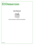
How an Ecovector® fan convector works
Hot water from your central heating system passes through the heat exchanger transferring
its heat to the aluminium fins. Cooler air is drawn in by the fan and heated as it passes
through the heat exchanger before being Expelled gently back into the room. Fan convectors
use around 25% less energy than a radiator to heat up a room, give a more even temperature
spread and achieve the required temperature in much less time.
This heater includes a selectable low
temperature cut out thermostat (set by your
installer dependant on the type of heat
generator) that prevents the fan from operating
until the central heating system water passing
through the heat exchanger reaches 38° for
renewable systems or 52C for boiler systems.
This prevents Ecovector® circulating cooler air
at start up.
Versatile, energy efficient heating
ECOVECTOR® High Level
Fan Convector
Heating
Models
Ensure your central heating system is on, the
heat output switch set to normal l and the fanonly switch set to RED (Heating). Providing the
water temperature in the system is more than
38°C and the thermostat/s controlling your
central heating system is calling for heat your
heater will switch on.
If you require a faster warm up move the heat
output switch to boost ll. moving the heat
output switch to 0 will turn off the heater.
HL 1000, HL 1000-12V
HL2300, HL2900, HL4000
INSTALLATION & USER GUIDE
Dear Installer,
Air Circulation (summer use)
Ensure central heating is off. Set the fan-only switch to BLUE and the heat output switch to
either l or ll. Ecovector® will run to provide a cooling flow of air. If the heater is being used
in conjunction with a room thermostat, the thermostat must be set to maximum.
Fault Finding
This heater is covered by a free five-year parts and labour guarantee. Please refer to the fault
finding section of the installation guide for advice. In the event of difficulty please contact us
on 01245 324560. it will be helpful if you do not disconnect the heater from the central
heating system.
The following items should be included in the carton:
•
•
Product complete with cable
Transformer (HL 1000-12V only)
In the event of items missing or visible damage please
contact us on 01245 324560. We would be most grateful if
you would leave this Installation & User Guide and the
Guarantee Registration Card with the owner of the property.
Thank you for your co-operation.
BRITISH MADE
BRITISH COMPANY
Smith’s Environmental Products Ltd,
Blackall Industrial Estate, South Woodham Ferrers, Chelmsford Essex CM3 5UW
Tel: 01245 324900 After Sales: 01245 324560 Fax: 01245 324422
E-mail: [email protected] Web: www.smiths-env.com
For Ireland (Republic & Northern), contact MT Agencies on 00 353 1 864 3363
Steve Russell
Technical Services Manager
In light of our policy of continuous development Smith’s Environmental Products Ltd reserve the right to
alter specifications without prior notice.
8
Feb 2012
Introduction
This heater is primarily intended for installation onto a wall at high level. The maximum
recommended installation height is 2.1 metres to the underside of the heater. There is no
clearance required above or to the side of the heater.
Electrical installations for these heaters must only be carried out by a suitably qualified person.
Versatile, energy efficient heating
Model HL 1000-12V
This model is designed for use in bathrooms and other high humidity areas. For these
applications it is essential that the heater, transformer and fused spur are installed in line with
current regulations relative to fixed current equipment in high humidity areas, wet rooms
and/or bath and shower rooms.
ECOVECTOR® High Level
Fan Convector
The transformer has been designed to fit into a surface-mounted or recessed pattress box
(not supplied) similar to those used for shaver sockets (47mm deep). The transformer can be
mounted horizontally or vertically however it must not be directly above the heater but should
be accessible after completion of the installation.
Models
HL 1000, HL 1000-12V
HL2300, HL2900, HL4000
Supply to the transformer must be via a 3 amp fused spur. The fused spur must not be
directly above the heater but should be accessible after completion of the installation. Twin
core cable is fitted to the product for connection to transformer. HL 1000-12V should not be
earthed
USER GUIDE
Models HL 1000, HL 2300, HL 2900 & HL 4000
These models must not be installed in bathrooms or other high humidity areas.
Ecovector® is classified as a fixed appliance and electrical connection should be via a 3Afused spur. The fused spur must not be directly above the heater but should be accessible
after completion of the installation. If the pre-wired mains cable is damaged it must be
replaced by the manufacturer, its service agent or similarly qualified persons. This appliance
must be earthed.
For models HL 2900 and HL 4000 we recommended that when securing the product to the
wall two persons should lift the heater into position.
All models
These heaters are designed for use on standard two-pipe pumped central heating systems.
Pipes are 15mm for models HL 1000, HL 1000-12V, HL 2300, HL 2900 and 22mm for model
HL 4000. Either pipe may be used as flow or return. These heaters are not suitable for onepipe systems.
We recommend the use of full flow isolating valves. The valves should be accessible after
completion of the installation. We also advise the fitting of an air vent at the highest point on
either the flow or return pipe to remove any air trapped within the system.
To avoid the possibility of vibration these heaters must be fitted on a flat even surface.
To conform to Building Regulations Part L (Part J in Scotland) these Ecovector® heaters can
be controlled by a remote wall mounted room thermostat (Smith’s Environmental Products
Part No. RT002). For further details please contact us on 01245 324560.
2
Dear Customer,
We are delighted you have chosen one of our products and trust you are
satisfied with the installation. We would ask you to take a few minutes to
read the User Guide to help you gain maximum benefit from your Ecovector®
fan convector. As with all our products your Ecovector® is covered by a
free five-year parts and labour guarantee and we would be grateful if you
complete and return the Guarantee Registration Card to us as soon as
possible. This will ensure that should you require assistance we can deal
with you quickly and efficiently.
Thank you for your co-operation.
Steve Russell
Technical Services Manager
01245 324900
P.s
Your Ecovector® is designed to operate as part of your central
heating system in the same way as a panel radiator. Providing you
leave the heat output switch in either the normal I or boost position
II and the fan-only switch set to RED your Ecovector® will switch
on and off automatically with your central heating system.
7
Heat output performance continued from page 5
Installation
Heat outputs are tested in accordance with BS4856. The temperature of the water in the
Central heating system will affect the heat output of this heaters. ∆t 60°C assumes a
Mean water Temperature of 80°C and a room temperature of 20°C. ∆t 50°C assumes a
mean water temperature of 70°C and a room temperature of 20°C. ∆t 20°C assumes a
Mean water Temperature of 40°C and a room temperature of 20°C.
Please note the guarantee may be invalidated if this product is not installed and used in
accordance with this guide.
1.
Fault Finding
1.
2.
Fan does not run on any switch setting.
a. Check the power supply is turned on.
b. Check the fuse in the fused spur.
c. Check the wiring connections at the fused spur.
No heat output on settings l or ll.
a. Vent any trapped air from the system (with the central heating
system turned OFF).
b. Check the central heating is turned ON.
c. If fitted ensure the room thermostat is calling for heat.
d. Balance the central heating system if installed on the same circuit
as panel radiators and increase the circulating pump speed if
required.
e. Increase the boiler water temperature.
CASING RELEASE SCREWS
2.
In the event of difficulty please contact us on 01245 324560. It will be helpful if
you do not disconnect the heater from the central heating system.
This appliance is not intended for use by persons (including children) with reduced
physical, sensory or mental capabilities, or lack of experience and knowledge,
unless they have been given supervision or instruction concerning use of the
appliance by a person responsible for their safety. Children should be supervised to
ensure that they do not play with the appliance.
Products with this symbol (crossed out wheelie bin) cannot be disposed as household waste.
Old electrical and electronic equipment must be recycled at a facility capable of handling these
products and their waste by-products. If you are purchasing replacement equipment your
retailer may offer a 'take back' scheme, or will be able to give details of the nearest approved
authorised treatment facility. Proper recycling and waste disposal will help conserve resources
whilst preventing detrimental effects on our health and the environment.
WEEE Registered Code: WEE/ED0093VW
Smith’s Environmental Products Ltd,
Blackall Industrial Estate, South Woodham Ferrers, Chelmsford Essex CM3 5UW
Tel: 01245 324900 After Sales: 01245 324560 Fax: 01245 324422
E-mail: [email protected] Web: www.smiths-env.com
For Ireland (Republic & Northern), contact MT Agencies on 00 353 1 864 3363
In light of our policy of continuous development Smith’s Environmental Products Ltd reserve
the right to alter specifications without prior notice.
6
Release the outer casing by
removing the screws on
the underside of the
casing.
Secure heater to the wall
using fixings suitable for
wall and level. If necessary
use packing to compensate
for uneven wall surfaces.
Maximum
recommended
installation height is 2.1
metres to the underside of
the heater. For models
2900
&
4000
we
recommend
that
two
persons should lift the
heater into position.
MAINS IN
SCREW FIXING
POINTS
SCREW FIXING
POINTS
2.1 METRE MAX HEIGHT
FROM FLOOR
3.
Connect
the
heating
system flow and return
pipes to the heater pipe
work. Do not use soldered
fittings to the heater pipe
work as the heat generated
could
damage
internal
wiring and components. We
recommend the use of full
flow isolating valves. The
valves should be accessible
after completion of the
installation. We also advise
the fitting of an air vent at
the highest point on either
the flow or the return pipe
to remove any air trapped
within the system. Check
for water leaks. Vent any
trapped air from the
heating system.
Return
Flow in
Ceiling
3
Full Flow
Service Valves
Installation Continued. – Electrical connection
COMMISSIONING
Models HL 1000, HL 2300, HL 2900, HL4000
1.
Electrical installations for these heaters must only be
carried out by a suitably qualified person. All
FUSED SPUR
electrical installation connections must comply with
BS7671, 1992 and IEE Regulations. Check the
voltage on the heater is correct supply for your supply. If in
doubt, consult a qualified electrician.
2.
3.
4.
5.
6.
4.
7.
Isolate the electrical supply and connect
the heater electric cable to the spur (3A).
The fused spur must not be directly above
the heater but should be accessible after
the installation is complete.
8.
Model HL 1000-12V
This model is designed for use in bathrooms and other high humidity areas. For these
applications it is essential that the heater, transformer and fused spur are installed in line with
current regulations relative to fixed current equipment in high humidity areas, wet rooms
and/or bath and shower rooms. Electrical installations for these heaters must only be carried
out by a suitably qualified person. All electrical installations must comply with BS7671, 1992
and IEE Regulations. Check the voltage on the heater is correct for your supply. If in doubt,
consult a qualified electrician.
The supplied transformer has been designed to fit into a surface-mounted or recessed
pattress box (not supplied) similar to those used for shaver sockets (47mm deep). The
transformer can be mounted horizontally or vertically however it must not be directly above
the heater but should be accessible after completion of installation.
Turn on electrical supply at the fused
spur.
Set the left hand (fan-only) switch to the blue dot and the right hand
(heat output) switch to ll, the fan should run at boost speed.
Turn on the central heating system.
Set the room thermostat (if fitted) to maximum.
Set the left hand (fan-only) switch to the red dot and the right hand
(heat output) switch to l or ll – heat will flow within a few minutes.
Balance the central heating system if the heater is installed on the
same circuit as panel radiators.
If the installation is working correctly remember to reset the room
thermostat (if fitted) to its normal setting.
Please leave this installation & user guide with the property owner for
future reference
Heat Output Performance
It is recommended that the Ecovector® High Level model is capable of maintaining
The calculated heat losses at normal heat output (l) enabling the boost settings (ll) to be
Used for faster heat up.
Heat Output ∆t
60°C
Model
Supply to the transformer must be via a 3 amp fused spur. The fused spur must not be
directly above the heater but should be accessible after completion of the installation. HL
1000-12V should not be earthed.
HL 1000
4.
Isolate the electrical supply and connect the mains side of the transformer to the
fused spur.
HL 2300
5.
Connect between the 12V side of the transformer and the heater using twin core
cable fitted to the product.
HL 2900
Installation Continued. – Final Assembly
6.
Refit the outer casing to the chassis
attaching the earth bonding connector
(not model HL 1000-12V) to the outer
Casing.
EARTH BONDING
4
HL 4000
HL 100012V
Normal
kW
(Btu/h)
1.0
(3500)
2.3
(7800)
2.9
(10000)
4.0
(13500)
1.0
(3500)
50°C
Boost
kW
(Btu/h)
1.4
(4700)
3.1
(10500)
4.2
(14500)
5.3
(18000)
1.4
(4700)
Normal
kW
(Btu/h)
0.9
(3100)
1.9
(6400)
2.5
(8500)
3.3
(11300)
0.9
(3100)
20°C
Boost
kW
(Btu/h)
1.1
(3800)
2.5
(8500)
3.5
(12000)
4.4
(15100)
1.1
(3800)
Normal
kW
(Btu/h)
0.4
(1300)
0.9
(3000)
1.1
(3800)
1.5
(5100)
0.4
(1300)
Boost
kW
(Btu/h)
0.5
(1800)
1.2
(4000)
1.6
(5500)
2.0
(6800)
0.5
(1800)
Heat outputs are tested in accordance with BS4856. The temperature of the water in the
Central heating system will affect the heat output of this heaters. ∆t 60°C assumes a
Mean water Temperature of 80°C and a room temperature of 20°C. ∆t 50°C assumes a
mean water temperature of 70°C and a room temperature of 20°C. ∆t 20°C assumes a
Mean water Temperature of 40°C and a room temperature of 20°C.
5