1
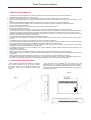
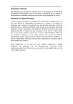
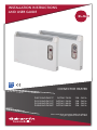
INSTALLATION INSTRUCTIONS AND USER GUIDE IECEE CB SCHEME CONVECTOR HEATER PH075 AND PH075T PH125 AND PH125T PH150 AND PH150T PH200 AND PH200T RATING 750 W RATING 1250 W RATING 1500 W RATING 2000 W 230 – 240 V~ 230 – 240 V~ 230 – 240 V~ 230 – 240 V~ Please read these instructions before installing or using this appliance for the first time Panel Convector Heaters 1.- IMPORTANT INFORMATION • • • • • • • • • • 2. – INSTALLATION INSTRUCTIONS - Open the carton at the indicated side. The screws are in the accessories bag. Turn the carton upside down to allow the heater to stand. Check that it is the correct model and that it is in good condition. - Fix the two square brackets to the back of the heater by using the two small screws (see Fig. 1). - When positioning the heater for installation it is important that a minimum clearance of 50 cm must be allowed between the heater and any combustible materials, such as furniture, curtains etc, to ensure the best heating results. Fig. 2 Fig. 1 41.0 cm 56.0 cm 63.5 cm 78.5 cm ( 750W) (1250W) (1500W) (2000W) 41.0 cm • mi n 20 cm • • • • • • • The warranty of the panel heater will not cover any damage caused by non observance of any of these instructions. This Guide must be kept and given to any new owner. Before connecting this appliance to any power supply, the wall fixing bracket located below has to be detached. Check that the voltage shown on the rating plate on the heater is the same as the voltage of the supply to which connection is to be made. Should the heater be moved and reinstalled it is essential that the work is carried out by a competent electrician. The use of panel heaters is forbidden in any area where there is a presence of gases, explosives or inflammable objects. Do not use this heater to dry clothes. Neither the connecting cable nor any other object must come into contact with the hot unit. Do not cover this heater at any time. The surfaces of this heater can be hot, so young children should not be left unsupervised in the vicinity of the heater. The air outlet grill at the top of the heater cabinet and the air inlet at the bottom of the heater are provided to ensure the most efficient operation of the appliance. They also protect the heater from overheating; therefore, it is essential that at no time are they covered. This heater should be disconnected from the electricity supply before any repair work is carried out. This action should also be taken during the times of the year when heat is not required. The panel heater should not be installed just below an electrical socket. The appliance must be installed in such a way that switches and other control devices cannot be touched by a person using a bath or shower. The installation must be carried out in accordance with the current electrical regulations. The heater is fitted with a flexible cable size 3 x 1.00 mm2 for electrical connection. It may be used to connect the heater to the fixed wiring of the premised through a suitable connection box positioned adjacent to the panel heater. This appliance must be connected to the supply by fixed wiring. The supply circuit to the heater must incorporate a double pole isolating switch having a contact separation of at least 3 mm. If the flexible power cable for this unit is damaged, it may only be replaced by a repair workshop recognised by the manufacturer, as special tools are necessary. This appliance must be earthed. Before carrying out any work inside the appliance, the panel heater must be disconnected from the electricity supply. The presence in the air of particles of smoke, dust and other pollutants could, in time, discolour the walls and surfaces around the panel heater. Please complete the enclosed warranty card and return it to the manufacturer to enable registration to take place. All models are supplied with an electrical interrupt cut-out. This will switch off the heater if, for any reason, it overheats. Should the cutout operate, turn the heater off and remove the cause for the overheating. The cut-out will be reset automatically. mi n 20 cm • • • • 8cm 10cm min 15cm 2 min 15cm Panel Convector Heaters - Position and fix the top bracket at the correct distance from the floor (see Fig. 2) and hang the unit on the hooks of the top bracket. Mark the fixing points on the wall using a pencil. Use the heater fixing holes as a template and mark the wall through the two fixing holes in the square brackets. Fix the heater to the wall. 3.- USING THE PANEL HEATER NON TIMER MODELS Open the hinged controls cover to access the controls. After adjustment the control cover closes automatically. Switch on the heater by setting one of the two switches marked I-O to “ I “. The off position is marked “ O “. You can select half heat or full heat by setting only one of the switches marked I-O to “ I “ or by setting the two ones (this feature is not available on 750W models). When the heater is generating heat the neon indicator on the switch will be illuminated. The heater is fitted with an adjustable thermostat, which enables room temperature to be controlled by adjusting the setting accordingly. Turn the thermostat control to the maximum (fully clockwise) to heat the room rapidly. When the desired temperature has been reached, turn the thermostat control slowly to the left (anti-clockwise) until the luminous indicator switches off. By leaving in this position, the heater will automatically maintain the selected temperature. TIMER MODELS If the slide switch marked I -O- ¹ is set to the position marked “ I “ the heater will be always on, under the control of the thermostat as a non timer model. If the slide switch marked I -O- ¹ heater will be in the off position. is set to the position marked “O “ the If the slide switch marked I -O- ¹ is set to the position marked “ ¹ “ the heater will operate automatically. Set the timer by rotating the dial clockwise until the correct time is indicated opposite the datum mark. Pull the appropriate segments out to set the desired programme. This programme will repeat itself every day. The timer may be set to give as many “on” periods of any length as may be required. The switch marked I – II provides a choice of half heat or full heat. (not available on 750W models). When the heater is generating heat the neon indicator on the switch will be illuminated. 3.- Cleaning and maintenance. Clean and dust with a dry, soft cloth only when the unit is disconnected and cold. Do not use solvents or abrasive products for cleaning. 3 Panel Convector Heaters 4.- WIRING T: E1: E2: S: C: L: Ta: PH-125T PH-150T PH-200T PH-075T PH-125 PH-150 PH-200 PH-075 WARNING: 24h Timer Element 1 Element 2 Safety cut out Switch Luminous indicator Ambient thermostat In order to avoid overheating do not cover the heater. The symbol on the product or in its packaging indicates that this product may not be treated as household waste. Instead it shall be handed over to the applicable collection point for the recycling of electrical and electronic equipment. By ensuring this product is disposed of correctly, you will help prevent potential negative consequences for the environment and human health, which could otherwise be caused by inappropriate waste handling of this product. For more detailed information about recycling of this product, please contact your local city office, your household waste disposal service or the shop where you purchased the product. These instructions are only valid in the EU member states. ELNUR UK Ltd. Unit 1, Brown Street North Leigh, Lancashire WN7 1BU www.elnur.co.uk Customer Service Department: Telephone +44(0)1942 670119 [email protected] Management System International Certifications: Manufactured by: ELNUR, S.A. Madrid, Spain www.elnur-global.com [email protected] As a part of the policy of continuous product improvement Elnur reserves the right to alter specifications without notice. INSTALLATION INSTRUCTIONS AND USER GUIDE WEB VERSION