1
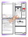
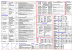
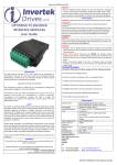
SAFETY NOTICES
OPTIDRIVE
HVAC RELAY
OPTION MODULE
WARNING is given where there
is a hazard that could lead to
injury or death of personnel.
CAUTION is given where there
is a hazard that could lead to
damage to equipment.
It is the responsibility of the
installer to ensure that the
equipment or system into which
the product is incorporated
complies
with
the
EMC
legislation of the country of use.
Within the European Union,
equipment into which this
product is incorporated must
comply
with
89/336/EEC,
Electromagnetic Compatibility.
WARNING
Within the European Union, all
machinery in which this product
is used must comply with the
Directive 89/392/EEC, Safety of
Machinery. In particular, the
equipment should comply with
EN60204-1.
WARRANTY
Complete Warranty Terms and
Conditions are available upon
request
from
your
IDL
Authorised Distributor.
User Guide
All rights reserved. No part of this User Guide may be reproduced or
transmitted in any form or by any means, electrical or mechanical
including photocopying, recording or by any information storage or
retrieval system without permission in writing from the publisher.
CAUTION
• Store the Option in its box until
required. It should be stored in a
clean and dry environment.
Temperature range –40oC to
+60oC.
• Install the Option onto the
Optidrive by inserting the row of
11 pins into the terminal connector
of the Optidrive, ensuring that the
terminals are tightened.
• If the Option is being used with
Size#1 Optidrive, care should be
taken to support the Option when
the terminal screws of the Option
are being tightened or loosened.
WARNING
• Optidrives and the Options
should be installed only by
qualified electrical persons and in
accordance
with
local
and
national regulations and codes of
practice.
• Electric
shock
hazard!
Disconnect and ISOLATE the
Optidrive before attempting any
work on it. High voltages are
present at the terminals and within
the drive for up to 10 minutes after
disconnection of the electrical
supply.
• Where the electrical supply to the
drive is through a plug and socket
connector, do not disconnect until
10 minutes have elapsed after
turning off the supply.
STANDARDS CONFORMITY
An Optidrive fitted with this Option complies with the
following standards:
• CE-marked for Low Voltage Directive.
• IEC 664-1 Insulation Coordination within Low Voltage Systems.
Copyright Invertek Drives Ltd ©2005
• UL 840 Insulation Coordination for electrical equipment.
The manufacturer accepts no liability for any consequences resulting
from inappropriate, negligent or incorrect installation.
The contents of this User Guide are believed to be correct at the time of
printing. In the interests of a commitment to a policy of continuous
improvement, the manufacturer reserves the right to change the
specification of the product or its performance or the contents of the
User Guide without notice.
• EN50081-2 EMC Generic Emissions Standard, Industrial Level.
• EN50082-2 EMC Generic Immunity Standard, Industrial Level.
• Enclosure ingress protection, EN60529 IP00, NEMA 250.
• Flammability rating according to UL 94.
SAFETY
This option is specifically designed to be used with the Optidrive
variable speed drive product and is intended for professional
incorporation into complete equipment or systems. If installed
incorrectly it may present a safety hazard. The Optidrive uses high
voltages and currents, carries a high level of stored electrical energy,
and is used to control mechanical plant that may cause injury. Close
attention is required to system design and electrical installation to avoid
hazards in either normal operation or in the event of equipment
malfunction.
System design, installation, commissioning and maintenance must be
carried out only by personnel who have the necessary training and
experience. They must read carefully this safety information and the
instructions in this Guide and follow all information regarding transport,
storage, installation and use of the Option module, including the
specified environmental limitations.
Invertek Drives Ltd
Offa’s Dyke Business Park
Welshpool
Powys
SY21 8JF
UK
Tel: +44 (0) 1938 556868
Fax: +44 (0) 1938 556 869
Please read the IMPORTANT SAFETY INFORMATION below, and all
Warning and Caution boxes elsewhere.
Part No. 82-HVACO-IN
Iss 1.00
email: [email protected]
Internet:www.invertek.co.uk
EXPLANATION
The HVAC Relay Option Module can be used in applications
where two indicators are required showing “drive running”
and “drive tripped”.
SPECIFICATIONS
Max Relay switching voltage:
250V AC / 220V DC
Max Relay switching current:
1A
Max input voltage :
+/- 50V DC
Environmental :
-10ºC … +50ºC
Conformity :
IP00, UL94V-0
OPTION COMPONENT LAYOUT
+10V O/P
Digital I/P 1
Digital I/P 2
Digital I/P 3
+10V O/P
Analog I/P
0V
Analog O/P
0V
Relay contact
Relay common
Relay 2 contacts
There are 2 variants of this option. The correct variant must be used
with the following products:
Optidrive
OD-HVACO-IN
Optidrive E
ODE-HVACO-IN
OPERATION
5
6
7
8
9 10 11
Optidrive size 2
Relay 1 contacts
4
500 Ω min.
3
0-10V analog O/P
Product Suitability
2
Closed: Enable; Open: Disable
Closed: Preset 1; Open: Analog I/P
Analog I/P - Closed: A; Open :V
1
Option PCB inserted into
Optidrive control terminal
strip.
All 11 terminal screws on
the Optidrive must be
tightened to ensure good
electrical contact and
correct functionality.
OPTION MODULE CONTROL TERMINALS
Programming the first relay output
Relay 2 contacts
P-18 = 3
Relay 1 closed when Optidrive output is at zero speed
P-18 = 4
Relay 1 closed when Optidrive output is not at maximum
P-18 = 5
Relay 1 closed when Optidrive output is not in overload
Digital Input 3
+10V Out
7
8
9 10 11
* Analog inputs should be connected to terminals 6 & 7.
(requested) speed
speed
Programming the second relay output
The second relay output has only one practical setting When P-18 = 1, Relay 2 is closed when Optidrive is running
NOTES
Relay contact
Digital Input 2
6
Relay common
Relay 1 closed when Optidrive output not at set
5
0V
P-18 = 2
4
Analog Output
Relay 1 closed when Optidrive tripped
3
*0V
Relay 1 closed when Optidrive disabled
P-18 = 1
2
* Analog Input 1
P-18 = 0
1
0V
Use the following information to set P-18 for other types of Relay
output:
Since the first relay output (fitted within the Optidrive) is
programmed using P-18 in the Optidrive, two completely
independent relay outputs are available. The following options are
supported for Relay 1 :
Digital Input 1
For typical operation set P-18 = 1, eg Relay 2 closed on enable
(Drive running – Green Light), Relay 1 closed when drive tripped
(Red Light).