1
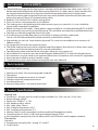
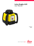
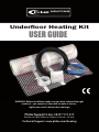
HEATING
Underfloor Heating Kit
USER GUIDE
WARNING: Before installation make sure you have selected the right
sized mat - you cannot cut the cable to make it shorter slightly too small is better than too large.
Philex Support Line: 08457 573 479
Monday to Friday 9.00am to 5.00pm (Local rate - UK only)
Technical Support: www.philex.com/heating
1
Introduction
Congratulations on the purchase of this Philex Heating product. The Philex Heating Kit is manufactured
from high quality materials and should give you many years of service.
To guarantee that your product functions correctly there are some key points described in these
installation instructions which must be followed closely.
The 10 year mat guarantee is valid only if the Philex Heating Kit is correctly installed in accordance with
the installation instructions in this guide and all other conditions detailed in the Warranty. Carefully
read this guide prior to installation, and ensure that you have the correct tools and materials to hand.
The electrical installation must be carried out by a qualified electrician in accordance with IEE
Regulations and conform to BS7671 and Part P of the Building Regulations.
If you have any questions or require more information then contact the
Philex Support Line: on 08457 573 479 - Monday to Friday 9.00am to 5.00pm
(Local rate - UK only)
or visit: Technical Support: www.philex.com/heating
Contents
Important - Do’s & Don’’ts.......................................................................................................3
Pack Contents.............................................................................................................................3
Product Specifications.............................................................................................................3
Preparation..................................................................................................................................4
Installation...................................................................................................................................4
Tools and Materials Needed..................................................................................................4
Floor Types...................................................................................................................................4
Installation Steps.......................................................................................................................5
Prepare the Subfloor................................................................................................................5
Orient the Floor Heating Mat................................................................................................5
Route the “Cold Tail” Connecting Lead..............................................................................6
Place the Temperature Sensor . ...........................................................................................6
Final Heating Mat Layout.......................................................................................................6
Embed the Heating Mat in Mortar......................................................................................6
Laying Ceramic or Quarry tiles.............................................................................................7
Installing the Thermostat ....................................................................................................7-8
Warranty....................................................................................................................................9-10
Resistance Readings Table....................................................................................................11
2
1. IMPORTANT - DO’s & DON’Ts
o Confirm before starting that the heating mat is the right size for the floor area- allow a min. 10cm (4”)
border around the full perimeter of the room and any fixed units (i.e. baths, basins, toilets, kitchen units etc.) or permanent furniture not on legs and calculate the remaining floor area in square metres.
You will also need to take into account that mats must not be laid over each other and that there must always be a space of 76mm (3”) between heating cables.
o Read this User Guide IN FULL before starting work.
o Don’t cut corners with preparation or installation.
o This heating mat is designed to be laid under ceramic, quarry or stone tiles. It is not suitable for
laying under carpeted or wood floors.
o Before starting you will need a 13Amp power supply wired from a suitable dedicated RCCD or RCBO
in the consumer unit running to the thermostat. This should be connected by a qualified electrician.
o The floor must be fully prepared, clean & dust free
o If installing on to a timber floor you must install an insulating sub-floor underneath.
You can use XPS thermal board insulation material available from retailers.
o Alternatively you can use 18mm exterior plywood. This must be screwed down at a minimum of
200mm centres.
o Do not position the mat over expansion joints.
o The Philex heating mat must not be installed under fixed objects like wall units, kitchen units, baths,
or showers and must be able to give off its warmth unhindered.
o The red heating cable, attached to the white glass fibre net, must not be cut.
o All installations in wet areas must be wired through a dedicated RCCD in line with the thermostat.
o All connections must be made by an approved electrician in accordance with current IEE regulations.
o Never connect a rolled up mat to a power supply.
o Check that the system works before covering the mats with adhesive.
2. Pack Contents
Please check before starting.
1.Heating mat with 2.25m connecting cable (cold tail)
2.Thermostat
3.Flexible floor temperature sensor, 3m length
4.Flexible conduit for temperature sensor
5.Installation Manual
6.Warranty Registration / resistance record card
Sensor Conduit
Heating Mat
Cold Tail
Thermostat
Temperature Sensor
3. Product Specifications
Heating mat
o Dimensions - all mats are 0.5m wide. Lengths available: 2m, 2.5m, 4m, 8m, 12m & 16m.
o Rating voltage: 230VAC
o Power unit: 150W/m2 +/-10%
o Min. bending radius: 30mm
o Min. cable space: 76mm
o Max. ambient temperature: 30°C
o Min. installation temperature: 5°C
o Heating Cable: 2 wires, grounded, insulation jacket by fluoropolymer plastic
o Connecting lead: 2 wires 17 AWG with ground braid, length 2.25m
o All components comply fully with all relevant EMC and LVD British and European standards
Thermostat
Functions:
o Temperature control by dial - setting: 5°C to 40°C
o On/off switch
3
Technical data:
o Voltage : AC 230V
o Power consumption : 5W
o Setting range : 5°C to 40°C
o Switching differential : 0.5K
o Ambient temperature : -5°C to +50°C
o Protective housing : IP20
o Housing material : anti-flammable PVC
o Floor sensor : rubber-thermoplastic NTC sensor, cable length 3m
4. Preparation
TAKE RESISTANCE READINGS before starting installation and note the results on your
warranty registration card and in the table on page 11.
o Plan your floor mat layout on paper before starting work.
o Determine where the thermostat is to be placed. Note that for bathroom installations the thermostat
must be located OUTSIDE the room.
o Place a standard mounting box with a min. depth of 35mm, at a convenient height (1.3 -1.5m).
o Cut out the necessary recess & channels and mount the back box and electrical conduit.
o You need to install two separate conduits, use the one supplied to hold the temperature sensor and
the other (not supplied) for the “cold tail” connecting cable.
o Do not run the power cable and sensor cable through the same conduit.
o Cut a channel in the floor for the floor sensor conduit (1cm deep).
o Ensure that the surface where the mat is being worked on is flat, clean, and free of dust and dirt.
PLEASE NOTE:
Make sure the sensor is not placed near to a radiator or hot water pipe running under the floor. Also
ensure it doesn’t pass under a heating cable.
5. Installation
5.1 Tools and Materials Needed
You will need the following items to install and test your Philex Heating Kit:
1. Scissors
2. Sharp knife
3. Wire stripper
4. Tape measure
5. Screwdriver
6. Multimeter
7. Room thermometer
8. Flexible tile adhesive or self-levelling mortar & flexible grout suitable for floor heating.
9. Flexible cement and cement gun for expansion joints along the walls.
10. 2m (approx) flexible electrical conduit (16mm) for “cold tail” cable run from floor to thermostat.
11. (Plastic) adhesive comb with approx. 6 mm teeth.
12. Mounting box for thermostat (min 35mm deep, preferably with Earth terminal).
13. 13Amp power supply wired from a dedicated RCCD in the consumer unit to the thermostat.
In addition you will need the appropriate tools and materials to install the particular floor, including
items like thin-set mortar, plywood or thermal backing board, notched trowel, and anything else for
your specific floor.
5.1.1 Sub-floor Types
This heating mat is primarily designed for installation on concrete floors. If laying onto a wooden floor,
it must be sheeted with a thermal board kit or similar cement covered board that is compatible with
heated floor systems.
Alternatively sheet the floor with 15mm WBP (Weather and Boil Proof plywood) or marine plywood,
fix with screws at 200mm centres and skim with 2-3mm of flexible tile adhesive and allow to dry.
5.1.2 Over- floor Types
This heating mat is designed to be laid under ceramic, quarry or stone tiles. It is not suitable for
laying under carpeted or wood floors.
4
5.2 Installation Steps
Follow these steps for a successful installation.
5.2.1 Prepare the Sub-floor
o Make sure that the floor area to be heated is clean (as dust free as possible), dry, flat and free of any
protruding objects that can damage the mat, like nails or staples.
o Drill or cut a hole through the wall sill plate under the position of the thermostat. You will use
this hole to route the connecting lead and the temperature sensor wire to the box.
Typical layout for a bathroom floor using 4m mat
PLEASE NOTE:
For bathroom installations
the thermostat must be
mounted outside the
bathroom
5.2.2 Orient the Floor Heating Mat
o Sketch out your room (see diagram) to decide how best to lay the mat.
o Lay out the mat according to your design with the red heating element uppermost, using as few
turns as possible and ensuring that the cold tail connecting lead is close enough to connect to
the thermostat.
o To make a turn in the direction the mat is being installed, cut the mesh WITH SCISSORS ONLY,
being careful not to damage the heating cable.
o If it is necessary to remove the heating cable from the mesh to route around an obstacle, be sure to
maintain at least 76mm space between heating cables. Also leave a space of at least 40mm
between heating cables and any conductive materials such as pipes.
5
5.2.3 Route the “Cold Tail” Connecting Lead
o Run the “cold tail” connecting lead as close as possible to
the wall en route to the thermostat.
o The “cold tail” must be routed outside of the heating mat,
never under or over the heating cable and it must not
protrude higher than the heating mat. Cut a groove in the
floor for the area of the join between the heating cable
and the “cold tail”.
o Run the “cold tail” inside a conduit inside the wall to the
thermostat mounting box.
Note: The rating label stuck to the end of the “cold tail”
should be visible in the thermostat mounting box. If it’s
necessary to shorten the connecting lead, be sure to peel
off the label and reattach so that it is visible in the
thermostat mounting box.
5.2.4 Place the Temperature Sensor
The Floor sensor must be placed in the sensor conduit
which must be embedded in a shallow channel in the floor,
making sure it reaches the end of the conduit but does not
protrude. (If required the sensor cable may be extended up
to 50m using 2 core 5A mains cable. DO NOT use 2 strands
of a multi-core cable as any voltage signals will disturb the
function of the thermostat.) The installation MUST USE a separate cable for the sensor mounted in a
separate conduit.
Centre the sensor between two runs of the heating cable, 100mm from the end of the heating
cable loop (see image 4). Run the sensor inside the wall to the thermostat box location.
Note: Don’t allow heating cable, connecting lead or temperature sensor to cross themselves or each
other. Sensor must be placed at least 50cm away from radiator/water pipes, drains and electrical wiring.
5.2.3 Final Heating Mat Layout
o Turn the mats over and remove the white plastic backing to the adhesive tapes on the back of the
heating mat then carefully reposition in the planned position and stick to the floor.
5.2.6 Perform Resistance Tests Before Embedding in Mortar.
TAKE RESISTANCE READINGS before embedding in mortar and note the results on your
warranty registration card and in the table on page 11.
Note: You must perform these tests before embedding the mat in mortar to confirm that the mat,
heating cable or sensor cable haven’t been damaged. This will support your guarantee.
Readings need to be taken with an ordinary Multimeter. Please also make a note of the
resistance readings on your inspection card.
5.2.7 Embed the Heating Mat in Mortar
After laying out the heating mat and routing the
connecting lead and the temperature sensor to the
electrical junction box, apply a thin coat of selflevelling mortar over the mat. Be sure to use the flat
side of the trowel to avoid any damage to the mat.
Spread the mortar evenly over the mat filling in all
voids between the floor, mesh and heating cable.
Once the surface is smooth and even, allow it to set
to a hard surface before installing the tile or stone.
6
5.2.9 Laying Ceramic or Quarry tiles
To lay ceramic or quarry tiles apply a layer of acrylic or latex modified thin-set using the ridged side of
your trowel. Tile and grout the floor using best industry practice and in accordance with instructions
provided by the manufacturer of the tiles. Ensure the grout has a flexible additive mixed in.
Don’t power the floor warming system until the thin-set and grout are fully cured (at least 14 days).
5.2.11 Repeat the Resistance Tests again after Completing Mat Installation.
TAKE RESISTANCE READINGS after all flooring is finished and prior to connecting up the thermostat
note the results on your warranty registration card and in the table on page 11.
Note: This will confirm that neither the mat, heating cable nor sensor cable have been damaged.
6.1 Installing the Thermostat
6.1.1 Electronic Heating Thermostat - General
This electronic thermostat is for mounting in a standard
wall box, and is adjustable to the required temperature
from +5°C to +40°C. The built-in red LED shows that the
heat is On.
6.1.2 Placement of the Thermostat
The thermostat must be mounted on the
wall with free air circulation around it.
It must be located where it is not influenced
by any other heating sources (e.g. the sun
shining through a window), draughts from
doors or windows, or by the temperature
of an exterior wall.
6.1.4 Wiring the Thermostat
The thermostat and mat require a 13 Amp dedicated power
supply from the consumer unit to power them and should be
wired as shown opposite. Connections should be
made by a qualified electrician. The Earth wires from
the cold tail should be connected to the mains Earth using the
Earth terminal in the mounting box or with a connector.
Mains
Lead
L
N
Sensor
Cold Tail - Mat
Connecting Lead
7
6.1.4 Mounting the Thermostat
Disassemble the thermostat as shown below. A 35mm deep or deeper wall mounting box should be
used and the thermostat fitted using the two screws provided.
6.1.5 Temperature Setting
The thermostat has a scale range of +5°C
to +40°C. To assist the adjustment, the
thermostat has a LED which will glow RED
when the heating is ON.
The thermostat should be set to the
maximum temperature setting until the
desired temperature of the room or floor
is achieved. The control knob should then
be turned back until the LED goes out.
Fine adjustments can be made over the
next 1 to 2 days to suit
individual requirements.
6.1.6 Thermostat Calibration
When the room temperature has been stabilized, the
thermostat set position may be adjusted to match
actual room temperature.
Measure the temperature of the room with an
accurate thermometer. Carefully remove the control
knob (1), without changing the setting, align the
knob to match the temperature measured and push
back onto the spindle (D).
NOTE: The temperature control is calibrated at the
factory, please do not move the control knob when
carrying out the installation.
6.1.7 Max./Min. Temperature Setting
A locking mechanism is positioned behind the control knob to limit the amount of adjustment
possible. By loosening the small screw C the scale range can be locked, e.g. between 20°C and 25°C.
The red ring limits the maximum temperature and the green ring limits the minimum temperature.
8
Warranty
o The Philex Heating mat is guaranteed to be free of manufacturing defects for a period of 10 years
from date of purchase.
o The thermostat is guaranteed to be free of manufacturing defects for a period of 2 years from date of
purchase.
o This warranty is subject to confirmation that all electrical work and connections have been
undertaken by a qualified electrician in accordance with IEE regulations and in accordance with these
installation instructions. Your mat must also be protected by a suitable RCCD.
Ensure that all installation work is compliant with current IEE wiring regulations and installations must
comply with Part ‘P’ of the Building Regulations. You should retain your Part ‘P’ certificate as proof of this
and send a copy with your registration card.
NOTE - These instructions have a section which must be completed with the name, company, address
and signature of the installation electrician.
o This warranty does not cover faults caused by incorrect installation or accidental damage. Statutory
rights are not affected.
This warranty applies:
1. Only to the original homeowner(s) from the date of purchase 2. Only if the unit is registered with
Philex within seventy five (75) days after purchase. Filling out the card accompanying this warranty in
its entirety will complete registration. In the event of a claim, proof of purchase is required, i.e. invoice
and receipt. Such invoice and receipt should state the exact model that was purchased; and 3. Only for
the duration of the Lifetime of the floor covering under which it was originally installed if the purchaser
of the heater remains the owner of the residence in which it was installed. If the original purchaser sells
such residence, the warranty will transfer and continue for the duration of the 10 years from date of
purchase. 4. Only if the heater has been grounded and protected by a RCCD (residual current circuit
breaker) at all times.
COVERAGE 1) The warranty period begins on the date of purchase. Registration is effective only when
a letter of confirmation is sent by Philex. 2) Philex’ Underfloor Heater is guaranteed by Philex Electronic
Ltd. to be free from defects in materials and workmanship under normal use and maintenance for
ten(10) years, provided the Product is installed in accordance with these instructions, and all
applicable local building and electrical codes; and 3) Provided Philex heaters are installed under
ceramic tile, marble and natural stone surfaces. 4) During the period of Warranty, Philex will arrange for
the heater to be repaired or (at its discretion) have parts replaced free of charge. The costs of repair or
replacements are your only remedy under this Warranty. Such cost does not extend to any cost other
than direct cost of repair or replacement by Philex and does not extend to costs of relaying, replacing
or repairing any floor covering or floor. 5) If Philex determines the repair of the product is not feasible;
we will replace the product with equal or similar features and functionality at Philex’ sole discretion.
PHILEX’ MAXIMUM LIABILITY IS LIMITED TO THE ORIGINAL PURCHASE PRICE OF THE HEATER .
EXCLUSIONS Philex Electronic Ltd. shall in no event be liable for incidental or consequential damages,
including but not limited to extra utility expenses or damages to property. This Warranty is null and
void if 1) The floor covering over the heater(s) is damaged, lifted, replaced, repaired or covered with
subsequent layers of flooring. 2) The heater fails due to damage caused during installation or tiling.
It is therefore essential to check that the heater is working (as specified in the installation manual) prior
to tiling. 3) Damage as a result of floods, fires, winds, lightning, accidents, corrosive atmosphere or
other conditions beyond the control of Philex. 4) Use of components or accessories not compatible
with the heater S) Philex products installed outside the United Kingdom. 6) Parts not supplied or
designated by Philex 7) Damage or repair required as a result of any improper use, maintenance,
operation or servicing. 8) Failure to start due to interruption and/or inadequate electrical service.
9
Warranty - continued
9) Any damage caused by frozen or broken water pipes in the event of equipment failure.
10) Changes in the appearance of the product that does not affect its performance. 11) The owner, or
his/her designated representative, attempts to repair the product without receiving prior
authorization from Philex. Upon notification of a repair problem, Philex Electronic Ltd. will issue an
Authorization to Proceed under the terms of this Warranty.
If Philex is required to inspect or repair any defects caused by any exclusions referenced above, all work
will be fully chargeable at Philex’ inspection and repair rates then in effect.
Philex Electronic Ltd. DISCLAIMS ANY WARRANTY NOT PROVIDED HEREIN, INCLUDING ANY
IMPLIED WARRANTY OF THE MERCHANTABLE OR IMPLIED WARRANTY OF FITNESS FOR A
PARTICULAR PURPOSE. Philex Electronic Ltd. FURTHER DISCLAIMS ANY RESPONSIBILITY FOR
SPECIAL, INDIRECT, SECONDARY, INCIDENTAL, OR CONSEQUENTIAL DAMAGES ARISING FROM
OWNERSHIP OR USE OF THIS PRODUCT, INCLUDING INCONVENIENCE OR LOSS OF USE. THERE ARE NO
WARRANTIES THAT EXTEND BEYOND THE FACE OF THIS DOCUMENT.
DUE TO DIFFERENCES IN BUILDING AND FLOOR INSULATION, CLIMATE AND FLOOR COVERINGS, Philex
MAKES NO REPRESENTATION THAT THE FLOOR TEMPERATURE WILL ACHIEVE ANY PARTICULAR
TEMPERATURE OR TEMPERATURE RISE. USERS MAY OR MAY NOT BE SATISFIED WITH THE FLOOR
WARMTH THAT IS PRODUCED.Philex Electronic Ltd. DOES WARRANT THAT ALL HEATERS WILL
PRODUCE THE RATED WATT OUTPUT LISTED ON THE HEATER NAMEPLATE, WHEN OPERATED AT THE
RATED VOLTAGE.
TERMS AND CONDITIONS Shipping Discrepancies: Incoming materials should be inventoried for
completeness and for possible shipping damage. Any visible damages or shortages must be noted
prior to accepting the material. Any discrepancy concerning type or quantity of material shipped, must
be brought to the attention of your Philex reseller within 15 days of the shipping date entered on the
packing slip for the order.
Miscellaneous: The terms of this limited Warranty are exclusive and supercede any other warranty or
terms and conditions relating to the subject matter whether included in a purchase order for this
product or in any other document or statement.
Making A Claim
Upon receiving a valid Warranty Registration Card, Philex Electronic Ltd. will issue a Warranty
Certificate and Reference Number which is to be quoted in any further warranty related
communications. To make a warranty claim contact :
The Warranty Department
Philex Electronic Ltd.
Philex House
Kingfisher Wharf
London Road
Bedford MK42 0NX
Tel:. 08457 573 479 (local rate number in the UK) Email: [email protected]
10
Resistance Readings TEST RESULTS
Please make a note of your resistance readings in the table below. This will support your guarantee.
Readings need to be taken with an ordinary Multimeter. Please also make a note of the
resistance readings on your registration card.
Readings 1., 2. and 3. are performed on the mat “cold tail” connecting lead and reading 4. on the
two wires of the floor temperature sensor.
Note: Your Mat Rating is marked on the label attached to the end of the blue mat “cold tail”
connecting lead.
Mat Rating:
W
Initial Test
Mat Laid
Completion
1. Live & Neutral
Ω
Ω
Ω
2. Live & Earth*
Ω
Ω
Ω
3. Neutral & Earth*
Ω
Ω
Ω
4. Floor Temperature
Sensor
Ω
Ω
Ω
* This should always read open circuit. If not, STOP immediately and call
Philex Support Line: 08457 573 479 (local rate number in the UK) Email: [email protected]
or visit: Technical Support: www.philex.com/heating
11