1
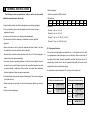
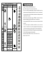
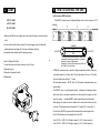
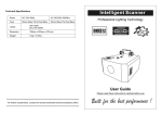
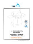
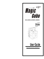
User Guide
Please read these instructions carefully before use
EC Declaration of Conformity
We declare that our products (lighting equipments) comply with the following
specification and bears CE mark in accordance with the provision of the
Electromagnetic Compatibility (EMC) Directive 89/336/EEC.
EN55014-2: 1997 A1:2001, EN61000-4-2: 1995; EN61000-4-3:2002;
EN61000-4-4: 1995; EN61000-4-5: 1995, EN61000-4-6:1996,
2C
EN61000-4-11: 1994.
&
Harmonized Standard
EN60598-1: 2000+ALL:2000+A12:2002
Safety of household and similar electrical appliances
Part 1 : General requirements
(3). By easy controller
The easy remote control is used only in master/slave mode. By connecting to
the 1/4” microphone jack of the first unit, you will find that the remote control on the
first unit will control all the other units for Stand by, Strobe/Next
and Fast/Slow function.
INDEX
1. STAND BY : stand by and blackout all the unit.
2. STROBE/NEXT : press the button and keep pressed up ,
when the unit is in fast mode, it will strobe by sound. If the
A. GENERAL INSTRUCTIONS
unit in slow mode, you can select the next color and gobo. It
will change ten colors and then change one gobo.
B. MAIN FEATURES
3. FAST/SLOW : when the led light off, it is in FAST mode. The unit movement by
sound activation. If the led light on, it is in SLOW mode, the unit movement
slowly.
E.
FIXTURE CLEANING
The cleaning of internal and external optical lenses and/or mirrors must be
3C
C. LAMP
D. HOW TO CONTROL THE UNIT
-----(1) By universal DMX controller
-----(2) Preprogrammed function
-----(3) By easy controller
carried out periodically to optimize light output. Cleaning frequency depends on the
environment in which the fixture operates: damp, smoky or particularly dirty
surrounding can cause greater accumulation of dirt on the unit’s optics.
• Clean with a soft cloth using normal glass cleaning products.
• Always dry the parts carefully.
• Clean the external optics at least once every 20 days. Clean the internal optics at
least every 30/60 days.
For further requirements, contact the nearest authorized technical assistance center.
E. FIXTURE CLEANING
A.
GENERAL INSTRUCTIONS
• Start the address
The following points are important for safety as well as for the smooth
1. Select the channels of DMX controller
installation and performance of the unit.
2. Dip switches
Dip
#1
Value
1
• Unpack carefully and be sure that no damage has occurred during shipping.
#2
2
#3
4
#4
8
#5
16
#6
32
#7
64
#8
128
#9
256
• Examples:
• It is very important to ground the yellow/green conductor in order to meet
Channel 1 : dip / on : #1 (=1)
regulations for safety.
Channel 4 : dip / on : #3 (=4)
• Do not connect the device to any dimmer pack or power pack.
Channel 7 : dip / on : #1, #2, #3 (1+2+3=7)
• The electrical work that is necessary for installation must do by qualified
Channel 10 : dip / on : #2, #4 (2+8=10)
personnel.
• Be sure to locate the unit in a place with adequate ventilation at least 15 cm from
(2). Preprogram functions
the walls. Be sure that no ventilation slots are blocked.
• Be careful that no liquids or other objects can enter the unit. If this ever happens,
disconnect the main power immediately.
• In the event of serious operating problems, turn off the unit immediately. Never try
to repair the unit yourself. Repairs carried out by non-qualified personnel can lead
to serious damage or malfunction. Please contact your dealer about authorized
•The unit can be linked together as master/slave in 2 or 4 channels and run by built
4C
in preprogrammed chase sequences by sound activation. When sound stops, all
the lights will shut down (blackout) immediately and then the bulb will turn off 15
seconds later. Please refer to the unit dipswitch-setting table for how to set the
dipswitches to achieve master/slave linking.
•In master/slave mode, the dipswitch 10 must be on of the master unit.
technical assistance. Always use genuine spare parts.
• Occasional breaks are necessary to prevent breakdowns. This unit is not designed
to be used non-stop.
2-Channels dip switches setting
4-Channels dip switches setting
Master
Master
Slave 1
Slave 1
• Always remember to unplug the unit from the mains power before any service is
done.
• Please recycle the packaging.
Slave 2
Slave 3
Gobos
DMX512 CONFIGURATION
DMX Channel 1
values
Shutter
255
Fast strobe
246
245
Channel 2
Gobo / Color
Fastest speed
B.
Channel 3
Reflector mirror
Stop
MAIN FEATURES
• Voltage : 120V 60Hz or 230/240/250V 50/60 Hz AC
14
• Bulb : EFP 12V 100W / JCR 15V 150W / ELC 24V 250W
• The unit is a DMX512 compatible lighting. It features full DMX512 control. One
13
gobo/color wheel with15 gobos plus shutter and 12 one color, 1 two colors and 1
four colors plus white, accurate focusable optics system and stepper motor with
12
blackout feature. Fan cooled.
• When the light receives blackout signal of DMX512, the bulb will shut down
11
(blackout) immediately and then the bulb will turn off 15 seconds later.
10
• It can be operated by DMX512 control or can be used as an individual unit without
a controller.
9
136
128
120
112
104
96
88
80
72
64
56
48
40
32
24
16
11
8
0
Slow strobe
Fast shaking
8
Slowest speed
Gobo 14 / Green +
Pink
Gobo 13 / White
Gobo 12 / Blue
Gobo 11 / Orange
Gobo 10 / Magenta
Gobo 9 / Pink
Gobo 8 / Light Blue
Gobo 7 / Magenta
Gobo 6 / Red
Gobo 5 / Orange
Gobo 4 / Green
Gobo 3 / Yellow
Gobo 2 / Blue
Slow shaking Gobo 1 / Multicolor
Stop
Open
Blackout
Stop
5C
required in 4 channels and run by built-in preprogrammed chase sequences by
sound activation through an internal microphone to create an intelligent effect.
7
6
5
4
3
2
1
Stop
• It can be linked together in master/slave combination, as many units as are
• Please use a quality 3 pin DMX cable / XLR plug when connecting them together.
• It features different preprogrammed chase patterns.
• Dimensions : 262mm x 240mm x 130 mm / 10.31in x 9.45in x 5.12in
• Weight : 5.8 kg / 12.76 lbs
C.
LAMP
D.
HOW TO CONTROL THE UNIT
(1). By universal DMX controller
EFP 12V 100W
The DMX512 is widely used in intelligent lighting control, with a maximum of 512
JCR 15V 150W
channels.
ELC 24V 250W
• Always switch off the main supply and never handle the lamp or luminaire when it
is hot.
• Do not touch the bulb with bare hands. If this does happen, clean the lamp with
COMMON
denatured alcohol and wipe with a lint free cloth before installing.
1
DMX INPUT
• Remember always replace with the same type lamp.
• How to change the lamp
2
3. Remove and replace the bulb.
4. Reassemble.
1
DMX +
3
DMX OUTPUT
2
DMX -
Termination reduces signal errors and to avoid signal
transmission problems and interference. It is always
advisable to connect a DMX terminal.
(Resistance 120 ohm 1/4W) between pin2 (DMX-) and
pin3 (DMX+) of the last fixture.
6C
1. Loosen the screw on the door located on font of the unit
2. Remove the door.
3
1
3
2
• A DMX512 system requires a controller, lighting equipment and cable. These are
connected together in a “daisy chain” with the terminator at the end. The cable
cannot be branched or split to a “Y” cable.
• The terminator requires a 90-120 Ohm 1/4 Watt resistor soldered between two
signal cables.
• The DMX512 uses a very high-speed signal.
Inadequate or damaged cables,
bad solder joints or corroded connectors can easily distort the signal and shut
down the system.
A reliable DMX512 system starts with good quality cables.
• Each lighting unit needs to have an address set to receive the data sent by the
controller. The address number is between 0-511 (usually 0 & 1 are equal to 1).
• The end of the DMX512 system should be terminated to reduce signal errors.
• 3 pin XLR connectors are more popular than 5 pin XLR.
3 pin XLR: Pin 1: GND, Pin 2: Negative signal (-), Pin 3: Positive signal (+)
5 pin XLR: Pin 1: GND, Pin 2: Negative signal (-), Pin 3: Positive signal (+)