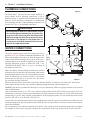
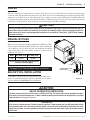
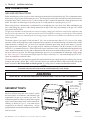
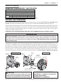
1
40
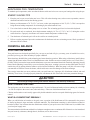
Section 5. Troubleshooting
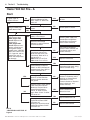
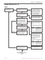
Heater Will Not Fire - C
Start
NO
Is “SERVICE HEATER” LED
“on”?
YES
If any red diagnostic LED’s
(AGS, AFS, SFS, HLS, PS, or
THERMISTOR) come “on”, go
to to Pages 42 and 43.
NO
Go to “INITIAL
TROUBLESHOOTING”
Turn off power to
heater for 5 seconds,
and turn back on.
Make sure temperature setting is above
water temperature.
Wait one minute.
YES
Does heater fire and
stay on?
CONTINUE
NO
NO
Did burner fire at all?
Did Blower come on?
YES
YES
Verify that gas is flowing to burner during
ignition try. Observe
gas meter for movement during ignition
try (wait for about 30
seconds after calling
for heat).
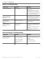
Go to “BURNER
TROUBLESHOOTING”
(Page 44)
Go to “HEATER WILL NOT
FIRE-D” (Page 41)
YES
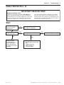
Replace Ignition Control
Module.
YES
NO
Check for 24 VAC between
VAL and GND terminals on
Ignition Control Module.
SEE NOTE 2.
Check for 24 VAC between
VAL and GND terminals on
Control Board. SEE NOTE 2.
NO
Fix wiring between VAL and
GND terminals of Ignition
Control Module and Control
Board.
YES
Replace Control Board.
NO
NO
Check for 24 VAC
between TH and GND
terminals on Ignition
Control Module.
SEE NOTE 1.
NO
YES
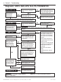
Continue to observe heater
for several minutes. Cycle
heater on and off several
times. Observe for delayed or
rough ignition, poor combustion, premature extinction of
flame, evidence of boiling, or
operation of any diagnostic
LED. Go to pertinent troubleshooting section if any
malfunction is observed.
Check for 24 VAC
between TH and GND
terminals on Control
Board. SEE NOTE 1.
Verify that gas supply is open
all the way to Gas Valve, and
Gas Valve is set at “on”
position.
Check for 24 VAC to Gas
Valve terminals during ignition
try. (Voltage appears about 24
seconds after call for heat).
SEE NOTE 2.
YES
Replace Gas Valve with
identical part.
YES
NO
Fix wiring between TH and
GND terminals of Ignition
Control Module and Control
Board.
Replace Control Board.
Check for 24 VAC
between GAS terminals on Control
Board. SEE NOTE 2.
YES
Fix wiring between GAS terminals on Control Board and
Gas Valve.
NO
Replace Control
Board.
NOTE 1: Voltage appears immediately after call for heat, and may be
on for only about 30 seconds.
NOTE 2: Voltage appears about 24
seconds after call for heat, and may
be on for only about 7 seconds.
MASTERTEMP® 125 Pool and Spa Heater Installation and User’s Guide
Rev. B 8/14