Transcript
MA00207
Dear Customer,
50652
50662
50672
50682
50692
50702
50712
50722
8.5T
7.5T
6.5T
5.5T
4.5T
4.0T
3.5T
3.0T
Precisensor™ system
12.5mm Sintered magnet
BRUSHLESS MODIFIED
easysolder design
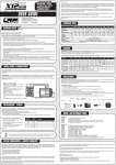
X12 - user guide
!
Please read the following instructions carefully before you start using your LRP VECTOR X12 Brushless Modified motor.
This user guide contains important notes for the installation, the safety, the use and the maintenance of this product.
Thus protecting yourself and avoid damages of the product.
This user manual shall be kept in a safe place. If another customer is using this product, this manual has to be handed
out together with it.
LRP electronic GmbH
Wilhelm-Enssle-Str. 132-134
73630 Remshalden
Germany
[email protected] www.LRP.cc
1.
thank you for your trust in this LRP product. By purchasing a LRP VECTOR X12 Brushless Modified motor, you have chosen
the highest developed competition brushless motor. LRPs R&D team took all the experience and testing results from the
last 4 years of practical tests and racinig with the LRP brushless motors on the highest levels of competition and started
with a clean sheet of paper for the all new X12 motors.
Proceed according to the user guide in order to understand your LRP VECTOR X12 Brushless Modified motor better. Please
take your time as you will have much more joy with your product if you know it exactly.
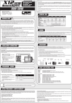
4. specification
warning notes
No toy. Not suitable for children under 14 years.
Keep the product out of the reach of children.
Pay close attention to the following points, as they can destroy the product and void your warranty. Non-observance of these points can lead to property damage, personal and severe injuries!
• Never leave the product unsupervised while it is switched on, in use or connected with a power source. If a defect
occurs, it could set fire to the product or the surroundings.
• Avoid incorrect connections or connections with reversed polarity of the product.
• All wires and connections have to be well insulated. Short-circuits can possibly destroy the product.
• Never allow this product or other electronic components to come in contact with water, oil or fuels or other electroconductive liquids, as these could contain minerals, which are harmful for electronic circuits. If this happens, stop the
use of your product immediately and let it dry carefully.
• Never open the product and never solder on the PCB or other components.
• Avoid overtightening the motor screws. Damaged threads are not covered under warranty!
• Avoid overloading the motor due to wrong or too long gear ratios.
• Never apply full throttle if the motor is not installed. Due to the extremely high RPMs without load, the motor
can get damaged.
• Always wire up all the parts of the equipment carefully. If any of the connections come loose as a result of vibration,
you could loose control over your model.
• Avoid soldering longer then 5 seconds per soldering joint when replacing the power wires to prevent possible damage to the
product due to overheating of the components. Use a high power soldering station with at least 60W for soldering.
The manufacturer can not be held responsible for damages, which are a result of non-observance of the warning
notes and security advices.
2. INSTALLATION / Connections
HALL-SENSOR WIRE: This bi-directional multipole wire, which is supplied with all LRP Sensored speed-controls, connects the speedo and the motor. Do not alter or modify this cable! Make sure, that the plugs have a proper and tight fit
and are always clean.
X12 VECTOR
8.5T
7.5T
Order No.
Voltage input
[V]
RPM1
Specific RPM/V [kV]
Power 1
[W]
Efficiency 1
[%]
Magnet material
Winding
Sensor assignment
50652
50662
6.5T
5.5T
4.5T
4.0T
3.5T
3.0T
50672
50682
50692
50702
50712
50722
4.8 - 7.4
4.8 - 6.0
30.240
33.840
38.800
45.360
56.880
63.360
72.000
83.520
4.200
4.700
5.400
6.300
7.900
8.800
10.000
11.600
307
340
394
463
565
621
698
797
93
92
92
91
91
90
89
88
Sintered 12.5mm (#50633)
Star (Multistrand Copper Winding)
Compliant to IFMAR/EFRA/ROAR/FEMCA/JMRCA/BRCA/DMC rules
Minimum speedo
requirement
SPX Super Reverse (#80400)
Sphere Comp. (#80700)
SPX Comp. StockSpec (#80710)
Sph.Co. TC-Spec 80750
SPX Bullet
Reverse 80450
Specifications subject to change without notice. 1Measured at 7.2V
5. gearing
Please pay special attention to our gear ratio recommendations! A wrong gear-ratio causes excessive heating and
may result in motor damage or thermal shutdown of your speed-control. Take your kits manual to find the correct pinion.
Please note, that following gear ratios are only a recommendation and a good starting point. The actual gearing may
vary due to different tracks, models, track conditions and/or batteries:
USAGE
Volts
8.5T
7.5T
6.5T
5.5T
4.5T
TC (small track)
6.0
6.8:1
7.4:1
7.8:1
8.2:1
8.6:1
TC (big track)
6.0
5.2:1
5.8:1
6.2:1
6.6:1
7.0:1
TC (small track) 7.2/7.4
7.5:1
8.0:1
8.5:1
9.0:1
9.5:1
TC (big track)
7.2/7.4
5.7:1
6.2:1
6.7:1
7.2:1
8.0:1
1:12
4.8
39.5mm 38.0mm 36.5mm 35.0mm 33.5mm
2wd Off-Road
7.2/7.4
10.2:1
--8.5:1
9.4:1
Truck Off-Road
7.2/7.4
9.5:1
12.2:1
-10.4:1
11.2:1
4wd Off-Road
7.2/7.4
7.0:1
8.0:1
10.0:1
11.0:1
9.0:1
Bold/Italic marked types are the LRP factory-team‘s recommendations for each class!
4.0T
3.5T
3.0T
9.0:1
7.7:1
9.6:1
8.2:1
10.0:1
-------
11.0:1
9.5:1
-------
8.7:1
-----
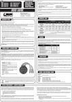
POWER WIRES: The unique splitted solder-tabs allow easy and convenient replacement of the power wires. Nevertheless some soldering skills are required. Talk to your local hobbyshop if you are concerned about soldering the wires
yourself.
Caution: Avoid soldering longer then 5sec per soldering joint to prevent possible damage to the motor due to overheating
of the inner components!
• Install the motor in the model.
Caution: The maximum length of the motor
screws shall not exceed 8mm.
• Connect the power wires of the speed-control to the motor.
Make sure, that the sequence is correct by
checking the color code and the letters:
- MOT.A = blue wire
- MOT.B = yellow wire
- MOT.C = orange wire
• If you‘re using a sensored speed-control:
attach the hall-sensor wire to motor and
speedo now.
• Finally check all the connections before using the motor.
blue
yellow
orange
Order No.:
Hall-Sensor wire
6. disassembly
Due to the maintenance free design of the LRP Vector X12, it is not necessary to open the motor frequently under normal
conditions. It is just recommended to check that all screws are still securely fastened.
Nevertheless, if you intend to check the ball bearings and oil them from time to time or want to change to another rotor
type, you can of course disassemble the motor.
Disassemble the motor:
1. Loosen the center endcover screw and remove screw, plastic endcover and timing insert.
2. Remove PreciSensor™ Assembly
3. Loosen and remove the long/outer 3 screws and gently slide off the front aluminium housing.
4. Remove the o-ring and shim from the shaft.
5. Carefully pull the rotor out of the housing and place it in clean towel or designated rotor container.
5. You have now access to both ball bearings for cleaning, maintenance and replacement. You may also use compressed
air to clean the inside of the motor after you have removed the bearings.
Be careful with correct shim/o-ring position during re-assembly and avoid overtightening the screws!
Endcover
3. precisensor™ System
M2.2 x 43
M2x6
Timing
Insert
PreciSensor
Assembly
Stack
Rotor
Shim O-Ring Front Housing
LRP‘s world exclusive PreciSensor™ System allows precise control for best and most efficient performace. Fast, simple
and super-accurate timing adjustment using the supplied timing inserts. By altering the timing, you move the powerband
and alter the characteristics of the motor.
Three important things to remember about timing adjustments:
1. Higher timing results in higher rpm but worse efficency/torque and vice versa.
2. Higher timing requires shorter gearing!
3. Timing adjustments should be done by experienced racers only, others please leave timing on standard setting!
To alter the timing, proceed as following:
1.Loosen the center endcover screw and remove screw and plastic endcover.
2.change to desired timing insert and rotate
sensor assembly slightly.
3.re-attach endcover and tighten M2 screw
carefully (do not overtighten this screw!
Finished!
Insert
Marking
Sensor
Timing
Comment
oooo
ooo
oo
o
-
X-10°
X-5°
X (Std.)
X+5°
X+10°
Standard insert, factory recommendation
The crossed-out wheeled bin means that within the European Union the product must be taken to seperate
collection at the product end-of-life. Do not dispose of these products as unsorted municipal waste.
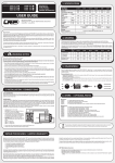
7. Spare- + optional parts
Spare parts:
#50620
#50633
#50622
#50623
#50624
X12 MR104ZZ ABEC5 Ball Bearings (2pcs)
X12 12.5mm Sintered Rotor
X12 Small Parts Set (includes: screws, endcover, timing inserts, shims, o-ring)
X12 PreciSensor Assembly (complete replacement sensor assembly, ready to use)
X12 Aluminium Front Housing
Optional parts:
#50621
X12 MR104ZZ Ceramic Ball Bearings (2pcs), for lowest friction
#50632
X12 Tuning Rotor Sintered - 12.0mm, for highest topspeed
#50634
X12 Tuning Rotor Sintered - 13.0mm, for maximum torque
#81910
Hall-Sensor Wire 20cm
#81920
Hall-Sensor Wire 10cm (shorter wire for 1/12, TC, etc)
#82505
Power-Wire Set Brushless 2.6mm² (red, black, blue, orange, yellow)
#82506
Power-Wire Set Brushless 3.3mm² (red, black, blue, orange, yellow)
#82510
Brushless+Brushed Cooling Set (specially made heatsink and high-performance fan)
repair procedures / limited warranty
All products from LRP electronic GmbH (hereinafter called “LRP”) are manufactured according to the highest quality standards.
LRP guarantees this product to be free from defects in materials or workmanship for 90 days (non-european countris only) from
the original date of purchase verified by sales receipt. This limited warranty doesn’t cover defects, which are a result of misuse,
improper maintenance, outside interference or mechanical damage. „This applies among other things on:
a fee at the customers expense according to our price list. A proof of purchase including date of purchase needs to be included.
Otherwise, no warranty can be granted. For quick repair- and return service, add your address and detailed description of the
malfunction.
• Overload (for example: unsoldered Star-ring)
• Excessive amounts of dirt inside the motor
• Rotor damage due to debris inside motor
• Mechanical damage due to external causes
• Rust“
The specifications like weight, size and others should be seen as guide values. Due to ongoing technical improvements, which are
done in the interest of the product, LRP does not take any responsibility for the accuracy of these specs.
To eliminate all other possibilities or improper handling, first check all other components in your model and the trouble shooting
guide, if available, before you send in this product for repair. If products are sent in for repair, which do operate perfectly, we
have to charge a service fee according to our pricelist.
With sending in this product, the customer has to advise LRP if the product should be repaired in either case. If there is neither
a warranty nor guarantee claim, the inspection of the product and the repairs, if necessary, in either case will be charged with
If LRP no longer manufactures a returned defective product and we are unable to service it, we shall provide you with a product that
has at least the same value from one of the successor series.
LRP-Distributor-Service:
• Package your product carefully and include sales receipt and detailed description of malfunction. • Send parcel to your national LRP distributor. • Distributor repairs or exchanges the product. • Shipment back to you usually by COD (cash on delivery), but this is subject to your national LRP distributor‘s general
policy.