1
6304 5016 – 05/2006 GB
For the user
Operating instructions
Logano GE615 boiler
Buderus
Logano GE 615
Buderus
Logano GE 615
Please read thoroughly before use.
Contents
Contents
Contents
1
2
1.1
1.2
Safety information and explanation
of symbols
For your safety
Explanation of symbols
3
3
3
2
2.1
2.2
2.3
Information about the Product
Product overview
EU Declaration of Conformity
Correct use
4
4
4
4
3
3.1
3.2
3.3
3.4
Regulations
Boiler room
Quality of heating water
The correct fuel
Maintenance interval
5
5
5
6
6
4
4.1
4.2
4.2.1
Commissioning and operation
Before switching on
Checking the operating pressure
When should you check the operating
pressure?
4.2.2 Checking the operating pressure
(sealed systems)
4.2.3 Checking the water level (open systems)
4.2.4 Topping up with heating water and
bleeding the system
4.3
Starting the heating system via the control panel
5
5.1
5.2
7
7
7
7
7
7
8
9
5.3
Shutting down the boiler
Shutting down the heating system
Shutting down the heating system because
of a risk of frost
Emergency measures
10
10
10
10
6
Faults
11
We reserve the right to make any changes due to technical modifications.
2
Operating instructions Logano GE615 boiler • Issue 05/2006
Safety information and explanation of symbols
1
1
Safety information and explanation of symbols
1.1
For your safety
Installation and operation
Warning: frost
z Installation and commissioning must only be carried
out by qualified installation engineers.
The heating system can freeze up in very cold weather
if it has been switched off:
z Observe all instructions to ensure correct operation.
z Leave the heating system switched on all the time.
z Only use the boiler for its intended purpose.
z If there is a fault: Reset the fault immediately or call
an installer.
Maintenance
z Customers are advised to sign an inspection/
maintenance contract with an authorised
contractor and to have the heating system
serviced annually.
z The operator is responsible for ensuring that the
heating system is safe and environmentally
compliant (legislation on emissions or requirements
applicable in respective country).
Caution: system damage
z Keep the combustion air free from aggressive
substances (halogenated hydrocarbons, for
example, contained in spray cans, solvents or
cleaning agents, paints and adhesives). This
prevents corrosion.
z Prevent heavy contamination of the combustion air
by dust, airborne seed, etc.
z Do not hang up any washing to dry in the boiler room.
Read and observe the safety information and
codes of conduct:
If you can smell gas, there is a risk of an explosion
z Close the gas shut-off valve.
Caution: environmental damage from oil leaks
z If using oil as a fuel: Arrange immediately for an
installer to investigate and rectify the cause of any oil
leaks.
z Open window(s).
z Do not operate electrical switches and mobile
phones.
1.2
z Extinguish all naked flames.
Explanation of symbols
Safety information throughout the
document is signalled by a warning triangle
contained within a frame.
z From outside the building: call gas supplier,
authorised installer and emergency services.
If you can smell flue gases, there is a risk of poisoning
z Switch off the heating system (page 10).
z Open windows and doors.
Signal terms indicate the seriousness of the ensuing
risk if measures for minimising damage are not taken.
z Inform an authorised installer or gas supplier.
– Caution means that slight material damage may
occur.
Risk of poisoning due to insufficient ventilation
during open flue operation
– Warning means that minor injury or severe
material damage may occur.
z Do not cover or reduce the size of ventilation
openings in doors, windows and walls. If you do, the
heating system must not be operated.
– Danger means that severe injury may occur. Very
serious cases may result in death
Notes are identified in the text by this
symbol. They are bounded by horizontal
lines above and below the text.
Risk of fire from explosive and inflammable
materials
z Inflammable materials or liquids (paper, thinners,
paints, etc.) must not be used or stored in the boiler
room.
Notes are included with important information for
situations in which there is no danger for persons or
equipment.
We reserve the right to make any changes due to technical modifications.
Operating instructions Logano GE615 boiler • Issue 05/2006
3
2
Information about the Product
2
Information about the Product
2.1
Product overview
This boiler is a low temperature boiler that complies
with DIN EN 303 for oil or gas combustion with
modulating boiler water temperature control and no
minimum return temperature.
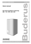
The main components of the Logano GE615 are:
– The boiler block transfers the heat generated by the
burner to the heating water.
– The boiler shell and insulation prevent energy loss.
– The control panel monitors and controls all electrical
boiler components.
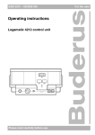
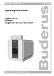
Fig. 1
2.2
Logano GE615 boiler
1
Boiler shell (casing)
2
Insulation
3
Boiler block
4
Control panel
EU Declaration of Conformity
The design and operation of this product
conform to the applicable European
directives and supplementary national
requirements. Its conformity has been
verified.
The Declaration of Conformity can be
viewed at www.heiztechnik.buderus.de or
alternatively can be requested from your
nearest Buderus sales office.
2.3
Correct use
The Logano GE615 boiler is intended for generating
heating water. You may use any type-tested oil or gas
fired burners to EN 267 or EN 676 provided their
operating range meets the boiler specification.
Using the boiler for any other purpose will be
considered improper use. Buderus accepts no liability
for any damage resulting as a consequence of such
use.
We reserve the right to make any changes due to technical modifications.
4
Operating instructions Logano GE615 boiler • Issue 05/2006
Regulations
3
Regulations
3.1
Boiler room
3
Caution: Boiler damage
Caution: System damage
Through contaminated combustion air.
through corrosion or scale formation as the
result of using fill and top-up water that
does not conform to the system-specific
requirements.
z Never use chlorinated cleaning agents
or halogenated hydrocarbons (as, for
example, contained in spray cans,
solvents or cleaning agents, paints
adhesives and thinners).
z Prevent heavy build ups of dust.
Caution: System damage
through water.
z In case of an acute risk of flooding,
disconnect the boiler from its power
supply and shut off the fuel supply
before water enters the boiler room.
z After a flood, have the heating system
checked by a installer before recommissioning.
z Ask your installer or water company for
details of the Ca(HCO3)2 concentration
(calcium hydrogen carbonate) in your
supply area.
z The fill and top-up water will have to be
treated if it does not meet systemspecific requirements. Consult your
installer if this is the case.
Your installer will enter the fill water level
and quality in the operator's log book,
which is maintained by the installer and
included in the technical documentation.
z Ask your installer to replace any valves
and control/regulating equipment that
have come into contact with water.
3.2
Quality of heating water
Water is used as the heat transfer medium in your
heating system. Water is given a different term
depending on its function in the system.
– Heating water:
Water contained within your heating system.
– Fill water:
Water used for the first filling of your system before
commissioning.
– Top-up water:
Water used to top-up your system in the event of
water loss.
All water contains substances, e.g. Ca (HCO3)2 (calcium hydrogencarbonate) that could affect the
operation of your heating system. These can cause
corrosion, scale formation or deposits.
We recommend that you regularly monitor the quality of
the fill and top-up water and treat it accordingly as and
when necessary to ensure correct operation of the
product.
We reserve the right to make any changes due to technical modifications.
Operating instructions Logano GE615 boiler • Issue 05/2006
5
3
3.3
Regulations
Correct fuel
This heating system requires fuel of the correct type
and grade to ensure its correct operation.
Follow the advice of your installer if you
want to convert your heating system to
another type of fuel or use fuel with a
different specification.
Your installer will enter in Table 2 (below)
which fuel is used in your heating system.
Caution: System damage
through unsuitable fuels.
z Use the specified fuel only.
System
Suitable fuels
EL heating oil
(to DIN 51603)
for Austria:
L heating oil
("Schwechat 2000"
light oil)1)
Natural gas,
LPG
Type:
Fuel used
Date/
signature
Tab. 1
3.4
Suitable fuels and fuel used
Maintenance interval
Heating systems should be regularly maintained for the
following reasons:
– to achieve a high level of efficiency and to operate
the system economically (low fuel consumption),
– to achieve a high level of operational reliability,
– to maintain the cleanest possible combustion.
Caution: System damage
through a lack of, or unsatisfactory,
cleaning and maintenance.
z Have your heating system inspected,
cleaned and maintained by your installer
once a year for gas and 2 for oil1.
z We recommend you sign a contract
covering an annual inspection and
maintenance on an as-required basis.
1.
If L heating oil ("Schwechat 2000" light oil) is being
used, cleaning and maintenance must be carried out
twice a year.
We reserve the right to make any changes due to technical modifications.
6
Operating instructions Logano GE615 boiler • Issue 05/2006
Commissioning and operation
4
Commissioning and operation
4.1
Before switching on
4
Before switching on, ensure that
– the operating pressure and fill level are correct,
– the fuel supply is open and
– the heating system emergency stop switch is
switched ON.
4.2
Checking the operating pressure
4.2.1 When should you check the operating pressure?
Recently topped-up heating water loses much of its
volume in the first few days because it releases gases.
This causes air pockets, and the heating system will
start to make a noise.
z After installing a new heating system, check the
operating pressure daily for the first few days. If
necessary top up with heating water and bleed the
radiators.
z After a while the operating pressure will only need to
be checked monthly. If necessary top up with heating
water and bleed the radiators.
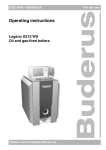
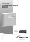
4.2.2 Checking the operating pressure (sealed
systems)
The registered installer will have set the red needle on
the pressure gauge to the required operating pressure
(at least 1 bar overpressure).
z Check that the pressure gauge needle is within the
green field.
z Top up with heating water if the pressure gauge
needle is below the green field.
6304 4901-04.0K
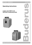
Fig. 2
Pressure gauge for sealed systems
1
Red needle
2
Pressure gauge needle
3
Green field
We reserve the right to make any changes due to technical modifications.
Operating instructions Logano GE615 boiler • Issue 05/2006
7
4
Commissioning and operation
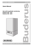
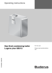
4.2.3 Checking the fill level (open system)
The installer has set the needle on the pressure gauge
to the required level.
z Check that the pressure gauge needle is within the
red field.
z Top up with heating water if the pressure gauge
needle is below the red field.
6304 4901-04.0K
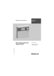
Fig. 3
Pressure gauge for open systems
1
Pressure gauge needle
2
Greenneedle
3
Red field
4.2.4 Filling the heating system
Filling and refilling of the heating circuit must been
carried out by a method that has been approved by the
Water Regulation Advisory Scheme (WRAS), for the
type of heating appliances, i.e. Domestic (in-house)
Fluid Category 3. Non-Domestic (other than in-house)
Fluid Category 4. Depending on the Fluid Category the
approved method should comprise of the following:
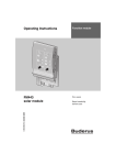
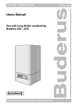
1. Requirements Fluid Category 3 systems (fig see
right)
z Control valve (stop valve) including a double check
valve on the mains cold water supply pipe
Fig. 4
Requirements Fluid Category 3 systems
Fig. 5
Requirements Fluid Category 4 systems
z Temporary connection to e removed after filling
(filling loop)
z Control valve (stop valve) on the heating system
pipework
2. Requirements Fluid Category 4 systems
(fig see right)
z Control valve (stop valve) on the mains cold water
supply pipe
z Strainer
z Verifiable Backflow Prevention Device with reduced
pressure Zone(RPZ valve assembly) incorporating
a Type BA air gap
z Tundish
z Control valve (stop valve) on the heating system
pipework
We reserve the right to make any changes due to technical modifications.
8
Operating instructions Logano GE615 boiler • Issue 05/2006
Commissioning and operation
4.3
4
Starting the heating system via the control panel
z Switch the boiler water thermostat to "AUT".
z Switch the ON/OFF switch on (position "I").
The entire heating system is switched ON.
z Check/adjust the following settings on the control
panel:
–
–
–
–
Automatic operating mode
Required room temperature
Required DHW temperature when required
Required heating program when required
Operating information can be found in the
control panel documentation.
Fig. 6
Switching on the heating system
1
Boiler water thermostat
2
ON/OFF switch
We reserve the right to make any changes due to technical modifications.
Operating instructions Logano GE615 boiler • Issue 05/2006
9
5
Shutting down the boiler
5
Shutting down the boiler
5.1
Shutting down the heating system
z Switch the ON/OFF switch on the control panel OFF
(position "0").
This switches the boiler and all its components OFF
(for example the burner).
z Close the main fuel shut-off valve.
Caution: System damage caused by frost
The heating system can freeze up in very
cold weather if it has been switched off.
z Leave the heating system switched on
all the time.
z Drain the heating system and DHW
pipework at the lowest possible point to
protect the heating system against
freezing whilst it is switched off.
Fig. 7
1
5.2
Switching off the heating system
ON/OFF switch
Shutting down the heating system
because of a risk of frost
If you need to shut down the heating system for a
lengthy period, during which frost might occur, the
heating system must be drained.
z Switch the ON/OFF switch on the control panel OFF
(position "0").
This switches the boiler and all its components OFF
(for example the burner).
z Close the main fuel shut-off valve.
z Drain the heating system and DHW pipework at the
lowest point. The automatic air vent at the highest
point of the heating system or the air vent valve on
the highest radiator must be open during draining.
5.3
Emergency measures
In the event of an emergency, e.g. a fire, proceed as
follows:
z Never risk your own life. Your own safety is
paramount.
z Close the main fuel shut-off valve.
z Isolate the heating system from the mains power
supply using the heating system emergency stop
switch or the corresponding domestic fuse.
z Contact the emergency services
We reserve the right to make any changes due to technical modifications.
10
Operating instructions Logano GE615 boiler • Issue 05/2006
Faults
6
6
Faults
Faults in the heating system are displayed on the
control panel display. For further information on the
fault displays please refer to the service instructions of
the control panel concerned.
Caution: System damage caused by frost
The heating system can freeze up in very
cold weather if it has been switched OFF
through a fault shutdown.
z Rectify the fault immediately and restart
the heating system.
z If this is not possible: Drain the heating
system and DHW pipework at the lowest
point.
Burner faults
A burner fault is also indicated by the fault lamp on the
burner.
Caution: System damage
Repeated pressing of the reset button can
damage the ignition transformer on the
burner.
z Do not press the reset button more than
three times in a row (for oil Burners
only).
z If the fault does not reset after the third
attempt: Try to identify the fault using the
burner documentation. Contact an
installer if necessary.
To reset burner faults:
z Press burner reset button.
We reserve the right to make any changes due to technical modifications.
Operating instructions Logano GE615 boiler • Issue 05/2006
11
Your installer:
Buderus
Cotswold Way, Warndon, Worcester WR4 9SW
Tel.: 01905 752794, Fax: 01905 753130
www.buderus-commercial.co.uk
In the UK, Buderus is a trading name of
BBT Thermotechnology Ltd.
BBT Thermotechnik GmbH
D-35573 Wetzlar
www.heiztechnik.buderus.de
[email protected]