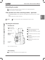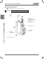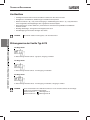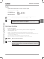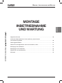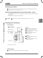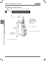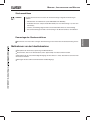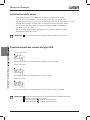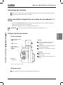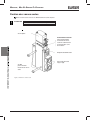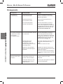
1
Operating Instructions
Bedienungsanleitung
Instructions de Service
c
V
or 24
V
2
ge 1
with ly
Volta R valid
n
U
ply o
UL / wer sup
2 po
lass
Type 5470
Block Assembly and Modular Pneumatic
Basic Rail MP05
Mehrfachblock und modulare, pneumatische
Grundschiene Type MP05
Bloc multiple et Profil pneumatique modulaire
Type MP05
We reserve the right to make technical changes without notice.
Technische Änderungen vorbehalten.
Sous resérve de modification techniques.
© 2000 Bürkert Werke GmbH & Co. KG
Operating Instructions 0606/10_EU-ML_00803136
CONTENTS
english
Contents of the
operating instructions for the
block assemblies
type 5470
modulare, pneumatic basic rail
type MP05
GENERAL NOTES ............................................................................................................................................................................................................................. 3
Symbols ................................................................................................................................................................................................................................................... 4
24V
r
o
V
4
Safety notes .....................................................................................................................................................................................................................................
2
ge 1 lid with
a
t
l
o
y
V
a
nl
Warranty conditions ................................................................................................................................................................................................................
5
UR v upply o
/
L
s
U
r
e
pow
2
s
clas
TECHNICAL DESCRIPTION ............................................................................................................................................................................................
7
Valve construction .................................................................................................................................................................................................................... 8
Valve operations of the type 5470 .......................................................................................................................................................................... 8
Media ......................................................................................................................................................................................................................................................... 9
Electrical connections ........................................................................................................................................................................................................... 9
INSTALLATION, INITIALISATION AND SERVICE ..................................................................................................................... 11
General Notes .............................................................................................................................................................................................................................. 12
Setting up block assemblies using the modular pneumatic
basic rails type MP05 .......................................................................................................................................................................................................... 12
Dismantling the module ................................................................................................................................................................................................... 13
Other possible uses of the connecting module, - right-hand - ...................................................................................... 13
Mounting the valve block ................................................................................................................................................................................................ 13
Mounting of single valves ............................................................................................................................................................................................... 14
Measures to be taken before putting into service ......................................................................................................................... 15
Faults ...................................................................................................................................................................................................................................................... 16
5470 / MP05 - 1
english
CONTENTS
2 - 5470 / MP05
english
GENERAL NOTES
GENERAL NOTES
Symbols ................................................................................................................................................................................................................................................. 4
Safety notes ..................................................................................................................................................................................................................................... 4
Warranty conditions ................................................................................................................................................................................................................ 5
5470 / MP05 - 3
GENERAL NOTES
Symbols
In these Operating Instructions, the following symbols are used:
indicates a working step that you will have to carry out.
english
ATTENTION!
NOTE
Indicates information which must be followed. Failure to do this could endanger your
health or the functionality of the device
Indicates important additional information, tips and recommendations.
Safety notes
To ensure that the device will function correctly, and have a long service life, please comply with the
information in these Operating Instructions, as well as with the application conditions and additional data
given in the Type 5470 data sheet:
• When planning the application of the device, and during its operation, observe the general technical
rules!
• Observe the relevant accident prevention and safety regulations applicable for electrical equipment
throughout the operation, maintenance and repair of the device; always switch off the voltage supply
before working on the system!
• Note that lines and valves must not be unscrewed from systems that are under pressure!
• Take suitable measures to prevent unintentional operation or impermissible impairment!
• If these instructions are ignored, no liability will be accepted from our side, and the guarantee on the
device and on accessories will become invalid!
NOTE
Approvals such as Ex, UL, UR, CSA, DVGW etc., will be indicated on the rating plate, or
by a special label.
If there are discrepancies, please contact immediately your Bürkert subsidiary or our customer service:
Bürkert Steuer- und Regelungstechnik, Service-department
Chr.-Bürkert-Str. 13-17, D-76453 Ingelfingen
Tel.: (07940) 10-111
Fax: (07940) 10-448
eMail: [email protected]
4 - 5470 / MP05
GENERAL NOTES
Warranty conditions
This document contains no warranty statements. In this connection we refer to our general sales and
business conditions. A prerequisite for validity of the warranty is use of the device as intended with
observance of the specified conditions of use.
The warranty covers only faultless condition of the Block Assemblies Type 5470
and Modular Pneumatic Basic Rails Type MP 05. No liability will be accepted for
consequent damage of any kind that max arise form failure or malfunctioning of
the device.
5470 / MP05 - 5
english
ATTENTION!
english
GENERAL NOTES
6 - 5470 / MP05
english
english
TECHNICAL DESCRIPTION
TECHNICAL
DESCRIPTION
Valve construction .................................................................................................................................................................................................................... 8
Valve operations of the Type 5470 ....................................................................................................................................................................... 8
Media ......................................................................................................................................................................................................................................................... 9
Electrical connections ......................................................................................................................................................................................................... 9
5470 / MP05 - 7
TECHNICAL DESCRIPTION
Valve construction
english
english
• 3/2 way pilot valve with various electrical connection possibilities.
• Valve body with diaphragm, seat seal and A/B manifolds.
• 2 (B) / 4 (A) service ports plus supply and venting ports 1 (P) / 3 (R), as option with internal thread.
Plug-in connectors or pointed hose nipples.
• The valve can be mounted on the modular pneumatic basic rail Type MP05 to form valve banks.
• Can be mounted in any position, preferably with the magnetic system at the top.
• Manual override for hand operation of the valve
NOTE
The valves require no maintenance, even for dry-air operation.
Valve operations of the Type 5470 valves
3/2 way valve
In de-energised position, pressure inlet 1 closed, outlet port 2 exhausted
3/2 way valve
In de-energised position, pressure inlet 1 connected to outlet port 2
4/2 way valve
In de-energised psotion, pressure inlet 1 connceted to outlet 2, outlet port 4 exhauseted.
NOTE
8 - 5470 / MP05
A simple conversion of the 4/2 way valve to a 3/2 way valve is
possible by closing off one of the service ports:
valve operation C;
Service port 2
Service port 4
valve operation D.
TECHNICAL DESCRIPTION
Media
• Filtered compressed air (max. particle size 10 µm), preferably non-oiled
• Seal material:
NBR
• Perissible medium temperature:
max. + 50 ° C
• Perissible ambient temperature:
max. + 55 ° C
• Operational pressure range:
2 - 8 bar
NOTE
ATTENTION!
The pilot pressure of the pneumatic controller is dependent on the pressure of the flow
of medium: it must not exceed a maximum of 8 bar!
Observe the permissible pressure range given on the rating plate!
Pressure difference between Ports 1 and 3 ³ 2 bar
For temperatures below 0 °C, operation is limited to dry-air operation.
Electrical connections
Pilot valve Type 6106
• Read the voltage, electrical power, type of protection and current from the rating plate!
• Voltage tolerance ±10 %;
• Ensure a long service life of the pilot valve by using a 10µ filter!
• Electrical connection: Instrument socket type 2506 to the tag connection on the coil (tigthening torque:
1 Nm);
• Proctection level IP 65 (only in combination with appliance socket type 2506);
• To match the cable run, the instrument socket can be mounted rotated by 180°.
NOTE
ATTENTION!
The coil heats up during opeation!
Take note of the voltage used; with alternating current, always
use the instrument socket Type 2506, or connect a rectifier into the circuit!
When screwing down the instrument socket onto the coil, ensure that the flat
seal is well seated!
5470 / MP05 - 9
english
english
• Operation is possible with oiled air
english
english
TECHNICAL DESCRIPTION
10 - 5470 / MP05
INSTALLATION , INITIALISATION AND SERVICE
english
english
INSTALLATION
INITIALISATION
AND SERVICE
General Notes ............................................................................................................................................................................................................................ 12
Setting up block assemblies using te modular pneumatic
rails Type MP05 ........................................................................................................................................................................................................................ 12
Dismantling the module ................................................................................................................................................................................................... 13
Other possible uses of the connecting module, - right-hand - ........................................................................................ 13
Mounting the valve block .............................................................................................................................................................................................. 13
Mounting the single valve ............................................................................................................................................................................................. 14
Measures to be taken before putting into service ........................................................................................................................... 15
Faults ...................................................................................................................................................................................................................................................... 16
5470 / MP05 - 11
INSTALLATION , INITIALISATION AND SERVICE
General Notes
Work on the valve should only be carried out by specialist staff and with the correct tools!
Before working on the system, always turn off the supply voltage!
Clean the piping system before installing the valve!
Where necessary, connect a strainer upstream to protect against faults.
When tightening the connections, never use the coil as a lever!
english
english
Ensure that the operational conditions agree with the performance data of the unit!
Avoid back-pressures in the exhaust channels by the use of large-volume silencers!
ATTENTION!
Lines or valves must never be loosened while the system is under pressure!
MANUAL OVERRIDE:
To operate the valve manually, turn the manual override by 90° in the direction of the arrow.
Setting up block assemblies using the modular
pneumatic rail MP05
With combination of two-way and three-way base modules, you can assemble valve blocks of any size.
NOTE
It is advisable to start the assembly with the left-most connector module (Fig. 1).
Check that each module is fitted with 2 O-rings!
Before locking together, lightly grease or oil the fitted O-rings.
Insert the lower hook of the module being added into the slot on the previous.
Lightly press te module being fitted upwards and latch in the upper locking hook.
Lay the 3 O-rings into the recess in the rear side of the valve. Ensure that the
seals are seated exactly!
ATTENTION!
Squashed O-rings sause leackages in the block!
Secure te valves to the base module using 2 screws each. (Tightening torque max. 0.5 Nm).
Mount the complete valve block onto the wall or the standard rail.
Connect the supply and working lines.
Make the electrical connections to the pilot valves: in doing this, observe the values given
on the rating plate!
12 - 5470 / MP05
INSTALLATION , INITIALISATION AND SERVICE
Dismantling the module
Unlatch the upper locking hook by using a screwdriver on the end dismantling-groove.
Remove the block part / module sideways.
• As a separation module for special applications when building up several pressure levels in a single
block.
• Additional supply lines for larger valve blocks.
NOTE
Where necessary, break out the rated break-points of ports 1 and 3.
Mounting the valve block
Standard rails
Electrical connection
can be rotated by 180 °
Wall mounting
Standard rail 35 x 15
or 35 x 7,5
EN 50022
Installation
Hang the valve block onto the upper
groove of the standard rail.
Latch the lower clamp into the standard
rail.
Firmly tighten the screws on the clamp.
Dismounting
Loosen the clamping screws (by about
4 revolutions).
Remove the block upwards from the
standard rail.
Connecting
module
Figure 2: Mounting the valve block
Wall mounting
Fix the module system directly to the wall using M4 screws.
5470 / MP05 - 13
english
english
Other possible uses of the connecting module, - right-hand -
INSTALLATION , INITIALISATION AND SERVICE
Mounting single valves
Fix the single valve directly to the wall using M4 screws.
english
english
ATTENTION!
When mounting, do not distort the valve body!
Pilot valve
Manual override
To operate the valve
manually, turn the manual
override by 90 °
in the direction of the
arrow
Designation plate
M4-screws
for wall mounting
the single valve
Fig. 3: Mounting single valve
14 - 5470 / MP05
Service ports
2(B) und 4(A)
INSTALLATION , INITIALISATION AND SERVICE
Plug-in connections
NOTE
For plug-in connections, the hose lines must meet the following requirements:
• Minimum rigidity of 40 Shore D (to DIN 53505 or ISO 868);
• External diameter corresponding to DIN 73378 (max. permissible deviation
± 0,1 mm from nominal dimension);
• Without burr, cut at right-angles ad with undamaged circumference;
english
english
• The hose lines must be pusched into the plug-in connectors up to the stop.
Dismantling the plug-in connections
To release the line, press in the pressure ring and pull out the hose line.
Measures to be taken before putting into service
Check all connections, voltages and the operational pressure!
Ensure that the max. operational conditions (see rating plate) will not be exceeded!
Check that ports 1 and 3 are correctly connected according to the regulations. These connections
must not be interchanged for any reason!
When operating electrically, unlock the manual override!
5470 / MP05 - 15
INSTALLATION , INITIALISATION AND SERVICE
Faults
Possible cause
Correction
Valve does not switch:
Operational voltage too low or
not present;
Check the electrical supply connections.
Ensure that the electrical power supply
is the same as that specified on the
rating plate.
Manual override not in neutral
position;
Set the manual override to the zero
position.
Compressed air supply not
available or insufficient.
Carry out the dimensioning of the
compressed air connection with
volumes as large as possible (including
that of upstream pressure regulators,
service units, cut-off valves etc.)
Minimum operational pressure ≥ 2
bar
english
english
Faults
Valve switch with a delay,
or exhaust through the
venting ports:
Compressed air supply not
available or insufficient;
Insufficient venting of the
exhaust channels due to
silencers that are too small or
are soiled (back-pressure);
Carry out the dimensioning of the
compressed air connection with
volumes as large as possible (including
that of upstream pressure regulators,
service units, cut-off valves etc.)
Minimum operational pressure ≥ 2
bar
Use silencers or expansion channels
with sufficient dimensions.
Clean soiled silencers.
Impurities or foreign matter in
the pilot valve or main valve.
Blast through the exhaust channels with
pulsed compressed air, to blow out
impurities.
Install a new pilot or main valve if these
measures bring no improvement.
Leaking valve block:
O-rings between the modules
missing or damaged;
Check for leaks and for missing seals.
Missing or incorrectly
positioned flat seals between
the valve and the baseplate.
16 - 5470 / MP05
Install the missing seals and replace
damaged seals.
INSTALLATION , INITIALISATION AND SERVICE
english
english
Notes
5470 / MP05 - 17
english
english
INSTALLATION , INITIALISATION AND SERVICE
18 - 5470 / MP05
INHALT
ALLGEMEINE HINWEISE .................................................................................................................................................................................................. 21
Darstellungsmittel ...................................................................................................................................................................................................................
22
r 24V
o
12V with
e
g
Sicherheitshinweise ............................................................................................................................................................................................................
ly
Volta R valid
y on
l
U
p
/
p
Garantiebestimmungen ...................................................................................................................................................................................................
su
UL
wer
o
p
s2
clas
22
23
TECHNISCHE BESCHREIBUNG ......................................................................................................................................................................... 25
Ventilaufbau .................................................................................................................................................................................................................................... 26
Wirkungsweise der Ventile Typ 5470 ............................................................................................................................................................. 26
Medien .................................................................................................................................................................................................................................................... 27
Elektrischer Anschluss ................................................................................................................................................................................................... 27
MONTAGE, INBETRIEBNAHME UND WARTUNG ..................................................................................................................... 29
Allgemeine Hinweise ............................................................................................................................................................................................................ 30
Aufbau des Mehrfachblocks mit der modularen, pneumatischen
Grundschiene Typ MP05 ............................................................................................................................................................................................... 30
Demontage der Module ................................................................................................................................................................................................... 31
Weitere Einsatzmöglichkeiten der Anschlussmodule, rechts ....................................................................................... 31
Befestigung des Ventilblocks ................................................................................................................................................................................... 31
Befestigung von Einzelventilen ............................................................................................................................................................................... 32
Maßnahmen vor Inbetriebnahme .......................................................................................................................................................................... 33
Störungen ........................................................................................................................................................................................................................................... 34
5470 / MP05 - 19
deutsch
deutsch
Inhaltsverzeichnis
der Betriebsanleitung
Mehrfachblock Typ 5470
Modulare, pneumatische Grundschiene
Typ MP05
deutsch
deutsch
INHALT
20 - 5470 / MP05
ALLGEMEINE HINWEISE
Darstellungsmittel ..................................................................................................................................................................................................................... 22
Sicherheitshinweise ............................................................................................................................................................................................................ 22
Garantiebestimmungen ................................................................................................................................................................................................... 23
5470 / MP05 - 21
deutsch
deutsch
ALLGEMEINE HINWEISE
ALLGEMEINE HINWEISE
Darstellungsmittel
In dieser Betriebsanleitung werden folgende Darstellungsmittel verwendet:
markiert einen Arbeitsschritt, den Sie ausführen müssen.
ACHTUNG
deutsch
deutsch
HINWEIS
kennzeichnet Hinweise, bei deren Nichtbeachtung Ihre Gesundheit oder
die Funktionsfähigkeit des Gerätes gefährdet ist.
kennzeichnet wichtige Zusatzinformationen, Tipps und Empfehlungen.
Sicherheitshinweise
Bitte beachten Sie die Hinweise dieser Betriebsanleitung sowie die Einsatzbedingungen und zulässigen
Daten gemäß Datenblatt Typ 5470, damit das Gerät einwandfrei funktioniert und lange einsatzfähig
bleibt.
• Halten Sie sich bei der Einsatzplanung und dem Betrieb des Gerätes an die allgemeinen Regeln der
Technik!
• Beachten Sie, dass in Systemen, die unter Druck stehen, Leitungen und Ventile nicht gelöst werden
dürfen.
• Beachten Sie die geltenden Unfallverhütungs- und Sicherheitsbestimmungen für elektrische Geräte
während des Betriebes, der Wartung und der Reparatur!
• Schalten Sie vor Eingriffen in das System in jedem Fall die Spannung ab!
• Treffen Sie geeignete Maßnahmen, um unbeabsichtigtes Betätigen oder unzulässige Beeinträchtigung
auszuschließen!
• Bei Nichtbeachtung dieser Hinweise und unzulässigen Eingriffen in das Gerät entfällt jegliche Haftung
unsererseits, ebenso erlischt die Garantie auf Geräte und Zubehörteile!
HINWEIS
Zulassungen wie Ex, UL, UR, CSA, DVGW usw. werden auf dem Typenschild oder durch
einen besonderen Aufkleber gekennzeichnet.
Bei Unstimmigkeiten wenden Sie sich bitte umgehend an Ihre Bürkert-Niederlassung oder an unseren
Kundenservice:
Bürkert Steuer- und Regelungstechnik, Service-Abteilung
Chr.-Bürkert-Str. 13-17, D-76453 Ingelfingen
Tel.: (07940) 10-111
Fax: (07940) 10-448
eMail: [email protected]
22 - 5470 / MP05
ALLGEMEINE HINWEISE
Garantiebestimmungen
Diese Druckschrift enthält keine Garantiezusagen. Wir verweisen hierzu auf unsere allgemeinen Verkaufs- und Geschäftsbedingungen. Voraussetzung für die Garantie ist der bestimmungsgemäße Gebrauch des Gerätes unter Beachtung der spezifizierten Einsatzbedingungen.
ACHTUNG
deutsch
deutsch
Die Gewährleistung erstreckt sich nur auf die Fehlerfreiheit des Mehrfachblocks Typ
5470 sowie der modularen, pneumatischen Grundschiene Typ MP05. Es wird keine
Haftung übernommen für Folgeschäden jeglicher Art, die durch Ausfall oder Fehlfunktion des Gerätes entstehen könnten.
5470 / MP05 - 23
deutsch
deutsch
ALLGEMEINE HINWEISE
24 - 5470 / MP05
TECHNISCHE BESCHREIBUNG
deutsch
deutsch
TECHNISCHE
BESCHREIBUNG
Ventilaufbau .................................................................................................................................................................................................................................... 26
Wirkungsweise der Ventile Typ 5470 ............................................................................................................................................................. 26
Medien .................................................................................................................................................................................................................................................. 27
Elektrischer Anschluss ................................................................................................................................................................................................... 27
5470 / MP05 - 25
TECHNISCHE BESCHREIBUNG
Ventilaufbau
• 3/2-Wege-Vorsteuerventil mit unterschiedlichen elektrischen Anschlussvarianten
• Ventilgehäuse mit Membran, Sitzdichtungen und A/B-Anschlussplatten
• Arbeitsanschlüsse 2 (B) / 4 (A) sowie Versorgungs- und Entlüftungsanschluss 1 (P) / 3 (R) wahlweise
mit Innengewinde, Steckkupplungen oder angespitzten Schlauchnippeln
• Die Ventile können auf der modularen, pneumatischen Grundschiene Typ MP05 zu Ventilblöcken
montiert werden.
• Beliebige Einbaulage, vorzugsweise mit Magnetsystem oben
• Handbetätigung für manuelles Betätigen des Ventils
des
u
ch
t
deutsch
HINWEIS
Die Ventile arbeiten wartungsfrei, auch bei Trockenlauf.
Wirkungsweise der Ventile Typ 5470
3/2-Wege-Ventil
In Ruhestellung Druckanschluss 1 gesperrt, Ausgang 2 entlüftet
3/2-Wege-Ventil
In Ruhestellung Druckanschluss 1 mit Ausgang 2 verbunden
4/2-Wege-Ventil
In Ruhestellung Druckanschluss 1 mit Ausgang 2 verbunden, Ausgang 4 entlüftet
HINWEIS
26 - 5470 / MP05
Durch Verschließen eines Arbeitsanschlusses ist ein einfacher Umbau des 4/2-Wegeventils in ein 3/2-Wegeventil möglich:
Arbeitsanschluss 2
Wirkungsweise C
Arbeitsanschluss 4
Wirkungsweise D
TECHNISCHE BESCHREIBUNG
Medien
• gefilterte Druckluft (Partikelgröße max. 10 µm), vorzugsweise ungeölt
• Betrieb mit geölter Luft ist möglich
• Dichtwerkstoff
NBR
• zulässige Temperatur
Medium
max. + 50 ° C
Umgebung max. + 55 ° C
HINWEIS
ACHTUNG!
2 - 8 bar
Der Steuerdruck bei pneumatischer Ansteuerung ist abhängig vom Druck des
Durchflussmediums; er darf maximal 8 bar betragen!
Beachten Sie den zulässigen Druckbereich auf dem Typenschild!
Druckdifferenz zwischen Anschluss 1 und 3 ≥ 2 bar
Bei Temperaturen unter 0 °C ist der Betrieb auf getrocknete Luft beschränkt!
Elektrischer Anschluss
Vorsteuerventil Typ 6106
• Entnehmen Sie Spannung, elektrische Leistung, Schutz- und Stromart dem Typenschild!
• Spannungstoleranz ±10 %
• Sorgen Sie durch 10 µ-Filterung für eine lange Lebensdauer des Vorsteuerventils!
• Elektrischer Anschluss: Gerätesteckdose Typ 2506 an den Anschlusssteckerfahnen der Spule (Drehmoment zur Befestigung: 1 Nm)
• Schutzart IP65 (nur in Verbindung mit der Gerätesteckdose Typ 2506)
• Die Gerätesteckdose ist zur Wahl der Kabelganges um 180° versetzt montierbar.
HINWEIS
ACHTUNG!
Die Spule erwärmt sich im Betrieb!
Beachten Sie die Spannung, verwenden Sie bei Wechselspannung unbedingt die
Gerätesteckdose Typ 2506 oder schalten Sie einen Gleichrichter vor!
Achten Sie beim Verschrauben der Gerätesteckdose mit der Spule auf einwandfreien
Sitz der Flachdichtung!
5470 / MP05 - 27
deutsch
deutsch
• Betriebsdruckbereich
des
u
ch
t
deutsch
TECHNISCHE BESCHREIBUNG
28 - 5470 / MP05
MONTAGE , INBETRIEBNAHME UND WARTUNG
deutsch
deutsch
MONTAGE
INBETRIEBNAHME
UND WARTUNG
Allgemeine Hinweise ............................................................................................................................................................................................................ 30
Aufbau des Mehrfachblocks mit der modularen, pneumatischen
Grundschiene Typ MP05 ............................................................................................................................................................................................... 30
Demontage der Module ................................................................................................................................................................................................... 31
Weitere Einsatzmöglichkeiten der Anschlussmodule, rechts ....................................................................................... 31
Befestigung des Ventilblocks ................................................................................................................................................................................. 31
Befestigung von Einzelventilen ............................................................................................................................................................................. 32
Maßnahmen vor Inbetriebnahme ........................................................................................................................................................................... 33
Störungen ......................................................................................................................................................................................................................................... 34
5470 / MP05 - 29
MONTAGE , INBETRIEBNAHME UND WARTUNG
Allgemeine Hinweise
Eingriffe dürfen nur durch Fachpersonal und mit geeignetem Werkzeug erfolgen.
Schalten Sie vor Eingriffen in das System in jedem Fall die Spannung ab.
Säubern Sie vor Montage des Ventils die Rohrleitungen.
Schalten Sie gegebenenfalls zum Schutz vor Störungen einen Schmutzfänger vor.
Verwenden Sie die Spule in keinem Fall als Hebel, wenn Sie die Anschlüsse einschrauben.
Achten Sie auf Übereinstimmung der Betriebsbedingungen mit den Leistungsdaten des Gerätes.
Vermeiden Sie Staudrücke in den Abluftkanälen durch großvolumige Schalldämpfer
deutsch
ACHTUNG!
In Systemen, die unter Druck stehen, dürfen Leitungen oder Ventile nicht gelöst werden!
HANDBETÄTIGUNG
Drehen Sie zur manuellen Betätigung des Ventils die Handbetätigung um 90° in Pfeilrichtung.
Aufbau des Mehrfachblocks mit der modularen, pneumatischen
Grundschiene Typ MP05
Sie erhalten durch die Kombination von 2fach- und 3fach-Grundmodulen beliebig große Ventilblöcke.
HINWEIS
Beginnen Sie die Montage zweckmäßig mit dem linken Anschlussmodul.
Kontrollieren Sie die Module auf vollständige Bestückung mit je 2 O-Ringen!
Ölen oder fetten Sie die aufgezogenen O-Ringe vor dem Rasten leicht ein.
Setzen Sie den unteren Haken des anzubauenden Moduls in die Nut des vorgehenden Moduls ein.
Drücken Sie das anzurastende Modul leicht nach oben und rasten Sie den oberen Rasthaken ein.
Legen Sie die 3 O-Ringe in die Aussparung auf der Rückseite des Ventils. Achten Sie dabei auf
exakten Sitz der Dichtungen!
ACHTUNG!
Gequetschte O-Ringe und Flachdichtungen haben Undichtheit des Blocks zur Folge.
Befestigen Sie die Ventile mit je 2 Schrauben auf dem Grundmodul (Anzugsmoment max. 0,5 Nm).
Montieren Sie den kompletten Ventilblock auf der Wand oder Normschiene.
Schließen Sie Versorgungs- und Arbeitsleitungen an.
Stellen Sie die elektrischen Anschlüsse zu den Pilotventilen her; beachten Sie dabei die Werte auf
dem Typenschild!
30 - 5470 / MP05
MONTAGE , INBETRIEBNAHME UND WARTUNG
Demontage der Module
Rasten Sie den oberen Rasthaken mittels Schraubendreher an der stirnseitigen Demontagenut aus.
Nehmen Sie den Teilblock / das Modul seitlich ab.
Weitere Einsatzmöglichkeiten der Anschlussmodule - rechts • Als Teilermodule bei besonderen Anwendungsfällen zum Aufbau von mehreren Betriebs-Druckstufen
in einem Block
HINWEIS
Durchstoßen Sie bei Bedarf die Sollbruchstellen der Anschlüsse 1 und 3.
Befestigung des Ventilblocks
Normschiene
Elektrischer Anschluss
um 180 ° drehbar
Wandbefestigung
Normschiene 35x15
oder 35x7,5
EN50022
Montage
Hängen Sie den Ventilblock mit der
oberen Nut in die Normschiene ein.
Rasten Sie die unteren Klemmstücke in
die Normschiene ein.
Ziehen Sie die Schrauben an den
Klemmstücken fest.
Demontage
Lösen Sie die Klemmschrauben (ca. 4
Umdrehungen).
Entnehmen Sie den Block nach oben
von der Normschiene.
Anschlussmodul
Bild: Befestigung des Ventilblocks
Wandmontage
Befestigen Sie den Ventilblock mit M4-Schrauben direkt an der Wand.
5470 / MP05 - 31
deutsch
deutsch
• Zusätzliche Einspeisung bei größeren Ventilblöcken
MONTAGE , INBETRIEBNAHME UND WARTUNG
Befestigung von Einzelventilen
Befestigen Sie das Einzelventil mit M4-Schrauben direkt an der Wand.
ACHTUNG!
Verspannen Sie das Ventilgehäuse beim Einbau nicht!
Vorsteuerventil
deutsch
Handbetätigung
Manuelle Betätigung:
Drücken Sie die Handbetätigung ein und drehen Sie sie um 90° in
Pfeilrichtung
Kennzeichnungsschild
Arbeitsanschlüsse 2(B) und 4(A)
M4-Schrauben
zur Wandmontage
des Einzelventils
Bild: Befestigung des Einzelventils
32 - 5470 / MP05
MONTAGE , INBETRIEBNAHME UND WARTUNG
Steckanschlüsse
HINWEIS
Für die Steckanschlüsse müssen die Schlauchleitungen folgende Anforderungen
erfüllen:
• Mindesthärte von 40 Shore D (nach DIN 53505 bzw. ISO 868);
• Außendurchmesser entsprechend DIN 73378 (max. zul. Abweichung ± 0,1 mm vom
Nennmaß);
• Gratfrei, rechtwinklig abgeschnitten und am Außendurchmesser unbeschädigt;
Demontage der Steckanschlüsse
Drücken Sie zum Lösen der Leitungen den Druckring ein und ziehen Sie die Schlauchleitung heraus.
Maßnahmen vor der Inbetriebnahme
Überprüfen Sie Anschlüsse, Spannung und Betriebsdruck!
Beachten Sie, dass max. Betriebsdaten (siehe Typenschild) nicht überschritten werden!
Überprüfen Sie die vorschriftsmäßige Belegung der Anschlüsse 1 und 3, diese dürfen auf keinen Fall
vertauscht werden!
Entriegeln Sie bei elektrischem Betrieb die Handbetätigung!
5470 / MP05 - 33
deutsch
deutsch
• die Schlauchleitungen sind bis zum Anschlag in die Steckanschlüsse einzudrücken.
MONTAGE , INBETRIEBNAHME UND WARTUNG
Störungen
mögliche Ursache
Behebung
Ventile schalten nicht:
keine oder nicht ausreichende
Betriebsspannung;
Überprüfen Sie den elektrischen
Anschluss.
Stellen Sie die Betriebsspannung laut
Typenschild sicher.
Handbetätigung nicht in neutraler Stellung;
Bringen Sie die Handbetätigung in NullStellung.
Druckversorgung nicht ausreichend oder nicht vorhanden.
Führen Sie die Druckversorgung möglichst großvolumig aus (auch bei vorgeschalteten Geräten wie Druckreglern,
Wartungseinheiten, Absperrventilen
usw.)
Mindestbetriebsdruck > 2 bar
Druckversorgung nicht ausreichend oder nicht vorhanden;
Führen Sie die Druckversorgung möglichst großvolumig aus (auch bei vorgeschalteten Geräten wie Druckreglern,
Wartungseinheiten, Absperrventilen
usw.)
Mindestbetriebsdruck > 2 bar
Keine ausreichende Entlüftung
der Abluftkanäle durch zu kleine oder verschmutzte
Geräuschdämpfer (Rückdrücke);
Verwenden Sie entsprechend groß dimensionierte Geräuschdämpfer bzw.
Expansionsgefäße.
Reinigen Sie verschmutzte Geräuschdämpfer.
Verunreinigungen bzw. Fremdkörper im Vorsteuer- oder
Hauptventil.
Beaufschlagen Sie die Abluftkanäle mit
impulsartigem Druck, um die Verunreinigungen auszublasen.
Bauen Sie ein neues Vorsteuer- bzw.
Hauptventil ein, wenn diese Maßnahme
keinen Erfolg bringt
Fehlende oder gequetschte ORinge zwischen den Modulen;
Ermitteln Sie die Leckstelle oder fehlende Dichtungen.
Fehlende oder falsch positionierte Flachdichtungen zwischen Ventil und Grundplatte.
Setzen Sie fehlende Dichtungen ein
oder erneuern Sie beschädigte Dichtungen.
deutsch
Störung
Ventile schalten verzögert oder blasen an den
Entlüftungsanschlüssen
ab:
undichte Ventilblöcke:
34 - 5470 / MP05
MONTAGE , INBETRIEBNAHME UND WARTUNG
deutsch
deutsch
Notizen
5470 / MP05 - 35
deutsch
MONTAGE , INBETRIEBNAHME UND WARTUNG
36 - 5470 / MP05
SOMMAIRE
REMARQUES GENERALES ........................................................................................................................................................................................... 33
Représentation ..........................................................................................................................................................................................................................
34
24V
34
35
DESCRIPTION TECHNIQUES ..................................................................................................................................................................................... 37
Construction de la vanne .............................................................................................................................................................................................. 38
Fonctionnement des vannes du type 5470 ............................................................................................................................................ 38
Fluides .................................................................................................................................................................................................................................................. 39
Raccordement électrique ............................................................................................................................................................................................. 39
MONTAGE, MISE EN SERVICE ET ENTRETIEN .......................................................................................................................... 41
Remarque générales .......................................................................................................................................................................................................... 42
Montage de blocs multiples avec les modules de base
pneumatiques MP05 .......................................................................................................................................................................................................... 42
Démontage des modules ............................................................................................................................................................................................. 43
Autres possibilitiés d’application du module de raccordement - à droite - ..................................................... 43
Fixation du bloc de vannes ........................................................................................................................................................................................ 43
Fixation des vannes seules ....................................................................................................................................................................................... 44
Précautions á prendre avant la mise en service ............................................................................................................................ 45
Dérangements ............................................................................................................................................................................................................................ 46
5470 / MP05 - 37
français
V or
2
1
e
Consignes générales de sécurité ......................................................................................................................................................................
g
with ly
Volta R valid
y on
l
U
p
/
p
Clauses de garantie ............................................................................................................................................................................................................
u
s
UL
wer
o
p
s2
clas
français
Table des matieres
Instructions de service
Blocs multiples et profils pneumatiques
modulaires Type 5470 et
Type MP05
français
SOMMAIRE
38 - 5470 / MP05
Représentation .......................................................................................................................................................................................................................... 40
Consignes générales de sécurité ...................................................................................................................................................................... 40
Clauses de garantie ............................................................................................................................................................................................................ 41
5470 / MP05 - 39
français
REMARQUES GENERALES
français
REMARQUES GENERALES
REMARQUES GENERALES
Représentation
On utilise dans ces instructions de service les modes de représentation suivants:
marque une phase de travail que vous devez exécuter;
ATTENTION!
REMARQUE
Caractérise des indications dont l’observation peut mettre en danger votre santé
ou la fonctionnalité de l’appareil;
Caractérise des indications supplémentaires, des conseils et des
recommandations;
français
Consignes générales de sécurité
Observez les indications de ces instructions de service ainsi que les conditions d’utilisation et les
caractéristiques admissibles selon la fiche technique du type 5470, afin que l’appareil fonctionne
parfaitement et reste longtemps en état de fonctionnement:
• respectez lors du projet d’utilisation et de l’exploitation de l’appareil les règles générales reconnues
de la technique;
• observez les dispositions en vigueur sur la prévention des accidents et la sécurité pour les
appareils électriques, pendant l’exploitation, l’entretien et la réparation de l’appareil; déclenchez dans
tous es cas la tension électrique avant toute intervention dans le système
• prenez les mesures appropriées afin d’exclure un actionnement involontaire ou un préjudice
inadmissible;
• observer que les conduites et les vannes des systèmes se trouvant sous pression ne doivent
pas être démontées;
• en cas d’inobservation de cette indication, toute responsabilité de notre part sera exclue, de
même la garantie sur l’appareil et les accessoires sera supprimée.
REMARQUE
Des homologations telles que Ex, UL, UR, CSA, DVGW, etc. sont indiquées sur la
plaquette signalétique ou sur une étiquette collante spéciale.
En cas de non concordance, s’adresser immédiatement à votre succursuale Bürkert ou `notre service
aprés ventre
Bürkert Steuer- und Regelungstechnik, Service-Abteilung
Chr.-Bürkert-Str. 13-17, D-76453 Ingelfingen
Tel.: (07940) 10-111
Fax: (07940) 10-448
eMail: [email protected]
40 - 5470 / MP05
REMARQUES GENERALES
Clauses de garantie
Ce document ne constitue aucun assentiment de 4 garantie. Nous vous renvoyons à cet effet à nos
conditions générales de vente et commerciales.La condition préalable au consentement de la garantie
est l’utilisation conforme de l’appareil à l’usage auquel il est destiné, compte tenu de l’observation des
conditions d’emploi spécifiées.
ATTENTION!
français
français
Les prestations de garantie ne s’étendent qu’à l’absence de défaut de la bloc
multiples et Profils pneumatiques modulaires Type MP05. Nous déclions,
par contre, toute responsabilité pour des dégâts consécutifs de toute nature
susceptibles de survenir par suite de défaillance ou défaut de fonctionnement
de l’appareil.
5470 / MP05 - 41
français
REMARQUES GENERALES
42 - 5470 / MP05
DESCRIPTION TECHNIQUES
Construction de la vanne .............................................................................................................................................................................................. 44
Fonctionnement des vannes du type 5470 ........................................................................................................................................... 44
Fluides .................................................................................................................................................................................................................................................. 45
Raccordement électrique ............................................................................................................................................................................................. 45
5470 / MP05 - 43
français
français
DESCRIPTION
TECHNIQUES
DESCRIPTION TECHNIQUES
Construction de la vanne
français
français
• Vanne pilote à 3/2 voies, avec différentes variantes de raccordement électrique.
• Corps de vanne avec membrane, joints du siège et plaque de raccordement A/B.
• Raccords de travail 2 (B) / 4 (A) ainsi que raccords d’alimentation et de purge d’air 1 (P) / 3 (R)
au choix avec taraudage, raccords à fiche ou raccords biseautés pour tuyaux souples.
• Les vannes peuvent être montées au choix sur le profil pneumatique modulaire du
type MP05 en bloc de vannes.
• Position de montage quelconque, de préférence avec système magnétique en haut.
• Actionnement manuel de la vanne.
REMARQUE
Les vannes travaillent sans exiger d’entretien, même en marche à sec.
Fonctionnement des vannes du type 5470
Vanne à 3/2 voies:
En position de repos, raccord de pression 1 bloqué, sortie 2 à l’air libre.
Vanne à 3/2 voies:
En position de repos, raccord de pression 1 relié à la sortie 2.
Vanne à 4/2 voies:
En position de repos, raccord de pression 1 relié à la sortie 2, sortie 4 à l’air libre.
REMARQUE
44 - 5470 / MP05
En fermant un raccord de travail, on peut transformer simplement la vanne à
4/2 voies en une vanne à 3/2 voies:
raccord de travail 2
mode de fonctionnement C
raccord de travail 4
mode de fonctionnement D
DESCRIPTION TECHNIQUES
Fluides
• Air comprimé filtré (grandeur max. des particules 10 µm), de préférence sans huile.
• Matière du joint:
NBR
• Température admissible du fluide:
max. + 50 ° C
• Température ambiante admissible:
max. + 55 ° C
• Domaine de pression de service:
2 - 8 bars
ATTENTION!
La pression de commande en pilotage pneumatique dépend de la pression du fluide
traversant; elle doit se monter au maximum à 8 bars!
Observez le domaine de pression admissible sur la plaquette signalétique!
Différence de pression entre raccords 1 et 3 ≥ 2 bars
Pour des températures inférieures à 0°C, le fonctionnement est limité à l’air sec.
français
REMARQUE
Raccordement électrique
Vanne pilote type 6106:
• Lisez sur la plaquette signalétique la tension, la puissance électrique, le genre de protection et de
courant!
• Tolérance de tension ± 10%;
• Assurez par un filtrage à 10 µm une grande longévité de la vanne pilote!
• Raccordement électrique: prise d’appareil type 2506 sur les fiches de raccordement de la bobine
(couple de serrage de la fixation: 1 Nm);
• Mode de protection IP 65 (seulement en relation avec la prise d’appareil type 2506;
• La prise d’appareil peut être montée inversée de 180° pour le choix du passage du câble.
REMARQUE
ATTENTION!
français
• Le fonctionnement avec de l’air huilé est possible.
La bobine s’échauffe en fonctionnement!
Observez la tension; utilisez en cas de tension alternative absolument
la prise d’appareil type 2506 ou placez un redresseur en amont!
5470 / MP05 - 45
français
français
DESCRIPTION TECHNIQUES
46 - 5470 / MP05
Remarque générales ........................................................................................................................................................................................................... 48
Montage de blocs multiples avec les modules de base
pneumatiques MP05 ........................................................................................................................................................................................................... 48
Démontage des modules ................................................................................................................................................................................................. 49
Autres possibilitiés d’application du module de raccordement - à droite - ..................................................... 49
Fixation du bloc de vannes ........................................................................................................................................................................................ 49
Fixation des vannes seules ...................................................................................................................................................................................... 50
Précautions á prendre avant la mise en service .............................................................................................................................. 51
Dérangements ............................................................................................................................................................................................................................ 52
5470 / MP05 - 47
français
MONTAGE,
MISE EN SERVICE ET
ENTRETIEN
français
MONTAGE , MISE EN SERVICE ET ENTRETIEN
MONTAGE , MISE EN SERVICE ET ENTRETIEN
Remarque générales
Des interventions ne doivent être effectuées que par un personnel qualifié équipé de l’outillage
approprié!
Déclencher dans tous les cas la tension avant toute intervention sur le système!
Nettoyer les conduites avant le montage de la vanne!
Monter éventuellement un filtre en amont pour prévenir des dérangements.
N’utiliser en aucun cas la bobine comme levier lors du vissage des raccordements!
Veiller à la concordance des conditions d’exploitation avec les caractéristiques de débit de l’appareil!
français
français
Eviter les accumulations de pression dans les canaux d’échappement d’air en employant des
silencieux de grand volume!
ATTENTION!
Ne pas démonter des conduites ou des vannes dans des systèmes se trouvant sous
pression!
ACTIONNEMENT MANUEL:
Pour l’actionnement manuel de la vanne, tourner l’actionnement manuel de 90° dans le sens de la
flèche.
Montage de blocs multiples avec le profil modulaire
pneumatique type MP05
On obtient en combinant des modules de base doubles ou triples des blocs de vannes de dimensions
illimitées.
REMARQUE
Commencer de préférence le montage par le module de raccordement
- à gauche - (figure 1)
Contrôler si les modules sont équipés de 2 joints toriques chacun!
Huiler ou graisser légèrement les joints toriques posés avant d’emboîter.
Introduire le crochet inférieur du module à ajouter dans la rainure du module précédent.
Presser le module à emboîter légèrement vers le haut et emboîter le crochet supérieur.
ATTENTION!
Les joint toriques écrasés ont pour conséquence des fuites dans le bloc!
Introduire les 3 joints toriques dans l’évidement à l’arrière de la vanne. Veiller alors à la tenue
exacte des joints!
Fixer les vannes sur le module de base avec 2 vis pour chacune (couple de serrage max. 0,5 Nm).
Monter le bloc de vannes complet sur la paroi ou le profil normalisé.
Raccorder les conduites d’alimentation et de travail.
Etablir les raccordements électriques aux vannes pilotes, en observant les valeurs sur la plaquette
signalétique!
48 - 5470 / MP05
MONTAGE , MISE EN SERVICE ET ENTRETIEN
Démontage des modules
Décrocher avec un tournevis le crochet d’emboîtement supérieur sur la rainure frontale de démontage
Extraire latéralement le bloc partiel / le module
Autres possibilités d’application du module de raccordement - à
droite français
• En tant que module diviseur pour des cas particuliers d’application, pour la réalisation de plusieurs
étages de pression de service en un seul bloc:
• Alimentation supplémentaire en cas de grands blocs de vannes
REMARQUE
Briser si nécessaire les points de passage des raccordements 1 et 3.
français
Fixation du bloc de vannes
Profil normalisé
Raccordement électrique
turnant de 180 °
Fixation murale
Profil normalisé
35 x 15 ou 35 x 7,5
EN 50022
Montage
Accrocher le bloc de vannes avec la
rainure supérieure dans le profil
normalisé.
Emboîter la pièce de serrage inférieure
dans le profil normalisé.
Serrer les vis sur les pièce de serrage.
Démontage
Dévisser les vis de serrage
(env. 4 tours).
Enlever le bloc du profil normalisé, vers
le haut.
Module de
raccordement
Figure 2: Fixation du bloc de vannes
Montage mural
Fixer le bloc de vannes avec 4 vis M4 directement contre la paroi.
5470 / MP05 - 49
MONTAGE , MISE EN SERVICE ET ENTRETIEN
Fixation des vannes seules
Fixer la vanne seule avec les vis M4 directement contre la paroi.
ATTENTION!
Ne pas déformer le boîter de vanne au montage!
français
Vanne pilote
français
Actionnement manuel
Tour l’actionnement
manuel de la vanne,
tourner l’actionnement
manuel de 90 ° sens
de la flèche
Etiquette d’identification
Raccords de travail
2(B) et 4(A)
Vis M4
pour la fixation
murale de la vanne
seule
Figure 3: Fixation de vanne seule
50 - 5470 / MP05
MONTAGE , MISE EN SERVICE ET ENTRETIEN
Raccords à fiches
REMARQUE
Pour les raccords à fiches, les conduites souples doivent remplir les exigences
suivantes:
• Dureté minimale de 40 Shore D (selon DIN 53505, resp. ISO 868)
• Diamètre extérieur selon DIN 73378 (écart max. adm. ± 0,1 mm de la cote nominale
• Exempt de bavures, coupé d’équerre et sans dommages sur le diamètre extérieur
Presser la bague de pression pour détacher les conduites et retirer les conduites souples.
Précautions à prendre avant la mise en service
Vérifier les raccordements, la tension et la pression de service!
Veiller à ce que les données de service maximales (voir plaquette signalétique) ne soient pas
dépassées!
Vérifier le raccordement conforme aux prescriptions des raccords 1 et 3, qui ne doivent en aucun cas
être permutés!
En cas de fonctionnement électrique, déverrouiller l’actionnement manuel!
5470 / MP05 - 51
français
Démontage des raccords à fiches
français
• Les conduites souples doivent être enfoncées jusqu’à la butée dans les raccords à
fiche
MONTAGE , MISE EN SERVICE ET ENTRETIEN
Dérangements
Cause possible
Remède
Les vannes ne
commutent pas:
Tension de service absente ou insuffisante;
Vérifier le raccordement électrique.
Assurer la tension de service selon la
plaquette signalétique.
Actionnement manuel
pas en position neutre;
Placer l’actionnement manuel en
position neutre.
Pression d’alimentation
absente ou insuffisante.
Exécuter l’alimentation en pression
avec le plus grand volume possible
(aussi avec les appareils en amont tels
que régulateurs de pression, unités de
conditionnement, vannes d’arrêt, etc.)
pression de service ≥ 2 bar
Pression d’alimentation absente
ou insuffisante.
Exécuter l’alimentation en pression
avec le plus grand volume possible
(aussi avec les appareils en amont tels
que régulateurs de pression, unités de
conditionnement, vannes d’arrêt, etc.)
pression de service ≥ 2 bar
Aération des canaux
d’échappement d’air
insuffisantes à cause de
silencieux trop petits ou sales
(contre-pressions).
Utiliser des silenci2eux resp. des vases
d’expansion dimensionnés assez
grands.
Nettoyer les silencieux sales.
Saletés ou corps étrangers
dans la vanne de pilotage ou
principale.
Appliquer des impulsions de pression
sur les canaux d’échappement d’air pour
expulser les saletés.
Monter une nouvelle vanne de pilotage
ou principale si cette mesure n’a pas de
succès.
Joints toriques absents ou
écrasés entre les modules;
Localiser la fuite ou les joints
manquants.
Joints plats absents ou mal
positionnés entre vanne et
plaque de base.
Poser les joints manquants ou remplacer
les joints endommagés.
français
français
Dérangement
Les vannes commutent à
retardement ou sifflent
aux raccords
d’échappement d’air:
Blocs de vannes pas
étanches:
52 - 5470 / MP05
Contact addresses / Kontaktadressen
Germany / Deutschland / Allemange
Bürkert Fluid Control System
Sales Centre
Chr.-Bürkert-Str. 13-17
D-74653 Ingelfingen
Tel. + 49 (0) 7940 - 10 91 111
Fax + 49 (0) 7940 - 10 91 448
E-mail: [email protected]
International
Contact addresses can be found on the internet at:
Die Kontaktadressen finden Sie im Internet unter:
Les adresses se trouvent sur internet sous :
www.burkert.com
Bürkert
Company
Locations
The smart choice
of Fluid Control Systems
www.buerkert.com