1
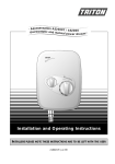
. T90si pumped e lectric shower . Installation and Operating Instructions INSTALLERS PLEASE NOTE THESE INSTRUCTIONS ARE TO BE LEFT WITH THE USER 2180285A Dec 99 T90si CONTENTS Page Important safety information 1 Introduction 2 Advice to users 2 Key to main components 3 Electrical requirements 4-5 Water requirements 6 Siting of the shower 6 Fitting the shower to the wall 8 Plumbing connections 8-9 Electrical connections 10 Commissioning 11 - 12 Fitting the riser rail 13 Fitting the hose and sprayhead 14 Operating the shower 15 - 16 Operating functions 16 Adjusting the sprayhead 17 Sprayhead maintenance 18 Filter maintenance 19 Fault finding 20 - 21 Spare parts 22 - 23 Temperature / flow rate graph 24 Guarantee, service policy, etc. rear cover This shower is designed for domestic use and is not vandal resistant. To ensure the product suitability for commercial and multiple installations, please contact Triton’s specification advisory service prior to installation. Telephone: (024) 7632 5491 Facsimile: (024) 7632 4564 E mail: [email protected] T90si PLEASE READ THIS IMPORTANT SAFETY INFORMATION ◆ Products manufactured by Triton are safe and without risk provided they are installed, used and maintained in good working order in accordance with our instructions and recommendations. ◆ DO NOT connect this shower directly to the mains water supply. ◆ DO NOT operate shower if frozen, or suspected of being frozen. It must thaw out before using. ◆ DO NOT operate the unit if the sprayhead or spray hose becomes damaged. ◆ DO NOT restrict flow out of the shower by placing sprayhead in direct contact with your body. ◆ DO NOT operate the shower if water ceases to flow during use or if water has entered inside the unit because of an incorrectly fitted cover. ◆ WARNING: If re-starting the shower immediately after stopping, be aware that a slug of hot water will be expelled for the first few seconds. 1 GENERAL 1.1 Isolate the electrical and water supplies before removing the cover. 1.2 Read all of these instructions and retain them for later use. 1.3 DO NOT take risks with plumbing or electrical equipment. 1.4 Isolate electrical and water supplies BEFORE proceeding with the installation. 1.5 The unit must be mounted onto the finished wall surface (on top of the tiles). DO NOT tile up to unit after fixing to wall. 1.6 Contact Customer Service (see back page), if any of the following occur; a) If it is intended to operate the shower at pressures above the maximum or below the minimum stated. b) If the unit shows a distinct change in performance. c) If the shower is frozen. 1.7 If it is intended to operate the shower in areas of hard water (above 200 ppm temporary hardness), a scale inhibitor may have to be fitted. 1.8 The sprayplate and cartridge must be cleaned regularly with descalent to remove scale and debris, otherwise restrictions to the flow on the outlet of the unit will result in higher temperatures and could also cause the Pressure Relief Device in unit to operate. 1.9 This product is not suitable for mounting into steam rooms or steam cubicles. 2 PLUMBING 2.1 The plumbing installation must comply with Water Regulations, Building Regulations or any particular regulations as specified by Local Water Company or Water Undertakers and should be in accordance with BS 6700. 2.2 The supply pipe must be flushed to clear debris before connecting to shower unit. 2.3 DO NOT solder pipes or fittings within 300mm of the shower appliance, as heat transfer can damage components. 2.4 DO NOT fit any form of outlet flow control as the outlet acts as a vent for the heater can. 2.5 DO NOT use excessive force when making connections to the flexible hose or sprayhead, finger tightness is sufficient. 2.6 All plumbing connections MUST be completed BEFORE making the electrical connections. 3 ELECTRICAL 3.1 The installation must comply with BS 7671 ‘Requirements for electrical installations’ (IEE wiring regulations) or any particular regulations as specified by the local Electrical Supply Company. 3.2 This appliance MUST be earthed. 3.3 In accordance with ‘The Plugs and Sockets etc. (Safety) Regulations 1994’, this appliance is intended to be permanently connected to the fixed wiring of the electrical mains system. 3.4 Ensure all electrical connections are tight to prevent overheating. 3.5 Fuses do not give personal protection against electric shock. 3.6 To enhance electrical safety a 30mA residual current device (RCD) should be installed in all UK electric and pumped shower circuits. This may be part of the consumer unit or a separate unit. 3.7 Switch off immediately at isolating switch if water ceases to flow during use. 3.8 Other electrical equipment i.e. extractor fans, pumps must not be connected to the circuits within the unit. 3.9 Switch off at isolating switch when not in use. This is a safety procedure recommended with all electrical appliances. 3.10 As with all electrical appliances it is recommended to have the shower and installation checked at least every two years by a competent electrician to ensure there is no deterioration due to age and usage. 1 T90si ADVICE TO USERS INTRODUCTION The following points will help you understand how the shower operates: This book contains all the necessary fitting and operating instructions for your T90si pumped electric shower – please read them carefully. The shower installation must be carried out by a competent person and in the sequence of this instruction book. 1 The electric heating elements operate at a constant rate at your chosen power setting. It is the flow rate of the water passing through the heater unit which determines the shower temperature at any given setting. (The slower the flow the hotter the water becomes, and the faster the flow the cooler the water). Do not attempt any electrical or plumbing work necessary to install this product unless you have good practical experience and adequate understanding of the IEE regulations and water regulations 2 During the Winter the cold water supply will be cooler than in the Summer months. Therefore, the temperature of the water will vary from season to season on any one setting of the temperature control, e.g. if you have chosen 'Medium' power for your preferred shower temperature in the Summer, you may have to increase that to 'Full' power during the Winter months (refer to temperature/flow rate graph on page 24). Care taken during the installation will ensure a long, trouble-free life from your shower. SPECIFICATIONS Electrical Nominal power rating at 240V Nominal power rating at 230V 8.5kW – (40A MCB rating) 9.5kW – (40A MCB rating) 7.9kW – (40A MCB rating) 8.8kW – (40A MCB rating) 3 If for any reason there is a sudden rise in water temperature, the T90si has thermal cut-out devices built-in (see items 2 and 3 under ‘Fault Finding’). Pump motor rating 120 Watt - single phase. Water Inlet connection – 15mm diameter. Outlet connection – 1/2” BSP male thread. 4 Switch off immediately at the isolating switch if water ceases to flow. Press the start/stop button and contact Triton Customer Service for advice. Entry Points Water – top, bottom or back. Cable – top, bottom or back. If ever the water becomes too hot and you cannot obtain cooler water, first check that the sprayplate in the sprayhead is not blocked. Materials Backplate, cover, controls, sprayhead – ABS. Elements – Minerally insulated corrosion resistant metal sheathing. Replacement parts can be ordered from Customer Service. See 'spare parts' for details and part numbers. Dimensions Height - 261 mm Width - 330 mm Depth - 104 mm Standards and Approvals Product conforms to EN 60335-2-35 and splashproof rating IPX4. Complies with the requirements of current British and European safety standards for household and similar electrical appliances. Complies with requirements of the British Electrotechnical Approvals Board (BEAB). Meets with Compliance with European Community Directives (CE). Due to continuous improvement and updating, specification may be altered without prior notice. 2 T90si Fig.1 1 5 7 6 2 122 mm 261 mm 14 9 8 11 4 12 3 5 13 44 mm 16 40 mm 15 5 10 17 18 330 mm MAIN COMPONENTS (Inside unit - fig.1) 1 2 3 4 5 6 7 8 9 10 11 12 13 14 15 16 17 18 PACK CONTENTS Top pipe / cable entry Motor assembly Pump assembly Bleed screw Wall screw fixing Power selector assembly Thermal cut-out (main) Terminal block Can and element assembly Area for bottom and back pipe/cable entry Pressure switch Temperature valve Solenoid valve Earth connection Inlet pipe Filter Thermal cut-out (outlet) Outlet pipe Shower unit Riser rail Sprayhead Sprayhead holder Riser rail brackets Hose Soap dish Fixing screws and plugs One year and extended guarantee options 3 T90si ELECTRICAL REQUIREMENTS WARNING THIS APPLIANCE MUST BE EARTHED The installation, supply cable and circuit protection must conform with IEE wiring regulations and be sufficient for the amperage required. The following notes are for guidance only: 1 The shower must only be connected to a 230/240V ac supply. If you are installing a shower with a kilowatt rating above 9kW, it is advisable to contact the local electricity supply company. 1.1 The electrical rating of the shower is shown on the rating label within the unit. 2 Before making any sort of electrical connection within the installation, ensure that no terminal is live. If in any doubt, switch off the whole installation at the consumer unit. 3 The shower must be connected to its own independent electrical circuit. IT MUST NOT be connected to a ring main, spur, socket outlet, lighting circuit or cooker circuit. Fig.2 schematic of installation circuit 3.1 The electrical supply must be adequate for the loading of the unit and existing circuits. 4 Check your consumer unit (main fuse box) has a main switch rating of 80A or above and that it has a spare fuse way which will take the fuse or mcb necessary for the shower (fig.2). 4.1 If your consumer unit has a rating below 80A or if there is no spare fuse way, then the installation will not be straight forward and may require a new consumer unit serving the house or just the shower. 4.2 You will need to contact the local electricity company. They will check the circuit and carry out what is necessary. They will also check the main bonding. 5 The earth continuity conductor of the electrical installation must be effectively connected electrically to all exposed metal parts of other appliances and services in the room in which the shower is to be installed, to conform to current IEE regulations. 5.1 All exposed metallic parts in the bathroom must be bonded together using a cable of at least 4mm2 cross sectional area. These parts include metal baths, radiators, water pipes, taps and waste fittings. Pull cord isolating switch Table A Shower unit RCD (can be part of consumer unit) Fuse or mcb CIRCUIT PROTECTION Consumer unit Meter Incoming supply fuse 80A or 100A main switch Meter tails 4 unit rating mcb cartridge fuse 7.0kW 30/32A 30A 7.5kW 32A 35A 8.0kW 40A 35A 8.5kW 40A 45A 9.0kW 40A 45A 9.5kW 40/45A 45A 10.5kW 45A 45A T90si ELECTRICAL REQUIREMENTS 6 For close circuit protection DO NOT use a rewireable fuse. Instead use a suitably rated miniature circuit breaker (MCB) or cartridge fuse (see table A). 6.1 To enhance electrical safety a 30mA residual current device (RCD) should be installed in all UK electric and pumped shower circuits. This may be part of the consumer unit or a separate unit. 7 A 45 amp double pole isolating switch with a minimum contact gap of 3mm in both poles must be incorporated in the circuit. 7.1 It must have a mechanical indicator showing when the switch is in the OFF position. 7.2 The wiring must be connected to that switch without the use of a plug or socket outlet. 7.3 The switch must be readily accessible and clearly identifiable, but out of reach of a person using a fixed bath or shower. 7.4 If the isolating switch is to be fitted in the bathroom, then it must be a cord operated type and should be placed so that it is not possible to touch the switch body when standing in a bath or shower cubicle. Twin and earth PVC insulated cable clipped direct or buried in a non insulated wall 6mm2 6mm2 6mm2 32A 38A 46A 10mm2 10mm2 10mm2 43A 52A 63A 16mm2 16mm2 16mm2 57A 69A 85A 8 Where shower cubicles are located in rooms other than bathrooms, any socket outlet in that room must be situated at least 2.5 metres from the shower cubicle. 9 The current carrying capacity of the cable must be at least that of the shower circuit protection (see table B). 9.1 To obtain full advantage of the power provided by the shower, use the shortest cable route possible from the consumer unit to the shower. 9.2 It is also necessary to satisfy the disconnection time and thermal constraints which mean that for any given combination of current demand, voltage drop and cable size, there is a maximum permissible circuit length. 10 The shower circuit should be separated from other circuits by at least twice the diameter of the cable or conduit. 10.2 In the majority of installations, the cable will unavoidably be placed in one or more of the above conditions. This being so, it is strongly recommended to use a minimum of 10mm cabling throughout the shower installation. CURRENT CARRYING CAPACITY in conduit or trunking Preferably it should be outside the shower enclosure and be readily accessible in order to switch off after using the shower. 10.1 The current rating will be reduced if the cabling is bunched with others, surrounded by thermal loft or wall insulation or placed in areas where the ambient temperature is above 30°C. Under these conditions, derating factors apply and it is necessary to select a larger cable size. Table B installed in a insulated wall 7.5 10.3 In any event, it is essential that individual site conditions are assessed by a competent electrician in order to determine correct cable size and permissible circuit length. Note: Cable selection is dependent on de-rating factors 5 T90si WATER REQUIREMENTS Fig.3 The installation must be in accordance with the Water Regulations / Byelaws. Minimum capacity 114 litres (25 gallons) WARNING: Under no circumstances must this T90si shower be connected directly to the mains water supply. Cold water cistern Gate valve Stop valve Mains electric supply (via double pole switch) 8cm (3") minimum To ensure activation of the heating elements, the shower must be connected to a cold water supply which is gravity fed from a static cold water storage cistern with a minimum capacity of 114 litres (25 galls). Double pole isolating switch There must be a maximum head of water of 10 metres (33ft) and a minimum head of 8 cm (3") as measured between the bottom of the cistern and the top of the shower unit. There must be no other cold water draw offs between the cistern and the unit and the pipe must not supply water to any other tap or fitting at a lower level. NOTE: The supply pipe from the cistern should be on the opposite side to the float operated valve to prevent air being drawn into the pipe when the cistern is filling. Shower unit Mains water supply If it is intended to operate the shower in hard water areas (above 200 ppm temporary hardness) a scale inhibitor should be fitted. Separate permanently connected supply from consumer unit Diagrammatic view (not to scale) Fig.3 shows a typical system layout. Do not use jointing compounds on any pipe fittings for the installation. SITING OF THE SHOWER WARNING: The shower must not be positioned where it will be subjected to freezing conditions. FOR EASE OF SERVICING, THE UNIT MUST ALWAYS BE MOUNTED ON THE SURFACE OF TILED WALLS. NEVER TILE UP TO THE UNIT. Refer to figure 4 for correct siting of the shower. This product is splash-proof rated and is approved for use in shower cubicles and over baths. However, do not install the unit in a position where the sprayhead will consistently direct water over it. The shower unit MUST be positioned vertically. Allow sufficient room between the ceiling and the shower to access the cover top screws. 6 T90si Pressure relief safety device Cold water supply from cistern (top, bottom or back) A pressure relief device (PRD) is designed into the shower unit which complies with European standards. The PRD provides a level of appliance protection should an excessive build up of pressure occur within the shower. DO NOT operate the shower with a damaged or kinked shower hose, or a blocked sprayhead which can cause the PRD to operate. Fig.4 Ceiling When commissioning, the sprayhead must be removed from the flexible hose. Failure to follow this procedure may also result in causing the PRD to operate. Ensure the shower is positioned over a bath or shower tray because if the PRD operates, then water will eject from the bottom of the unit. Should this happen, turn off the electricity and water supplies to the shower at the isolating switch and stopvalve. Contact Customer Service for advice on replacing the PRD. Height of sprayhead and shower to suit user’s requirement Shower can be mounted either side of the riser rail Outline of bath, shower tray or cubicle The PRD is situated behind the outlet pipe (fig.5). To gain access to it, FIRST ISOLATE THE ELECTRICITY SUPPLY, unscrew the hose then remove the cover. Remove the two screws holding the outlet pipe to the base of the can. Carefully pull away from the can and then unscrew the two screws holding the PRD to the outlet pipe. Shower unit must not be within an area 1 metre from base Diagrammatic view (not to scale) CAUTION: Do not attempt to replace the PRD unless competent to do so. NOTE: Before replacing the cover, it is strongly advised to prime the unit (see ‘commissioning’). Fig.5 Two outlet pipe screws Two PRD screws Outlet pipe PRD 7 T90si FITTING THE SHOWER TO THE WALL Fig.6 Important: The shower must be mounted on a flat surface which covers the full width and length of the backplate. It is important that the wall surface is flat otherwise difficulty may be encountered when fitting the cover and subsequent operation of the unit may be impaired. NOTE: The control knobs are an integral part of the cover – do not attempt to remove them. Unscrew the two top and two bottom retaining screws (fig.6) and lift the cover from the backplate. After choosing the site for the shower, use the backplate as a template and mark the three fixing holes (fig.7). Drill and plug to suit the fixing screws supplied. Screw the two upper fixing screws into position leaving the base of the screw heads protruding 6mm (0.25in) out from the wall. Hook the backplate over the top screws and fit the lower fixing screw into position. DO NOT fully tighten the screws at this stage, as the fixing holes are elongated to allow for out of square adjustment after the plumbing connections have been completed. NOTE: A temporary factory fitted locking screw is fitted to the power selector spindle (fig.15). This is to ensure the spindle is held in ‘COLD’ whilst the commissioning procedure is carried out. DO NOT remove before this procedure is completed. Fig.7 PLUMBING CONNECTIONS Plumbing to precede wiring. WARNING: The outlet of the shower acts as a vent and must not be connected to any tap or fitting not recommended by Triton Plc. DO NOT use jointing compounds on any pipe fittings for the installation. DO NOT use soldered fittings within the vicinity of the shower unit. NOTE: An additional gate valve or fullway lever valve must be fitted in the water supply to the shower as an independent means of isolating the water supply should maintenance or servicing be necessary. 8 T90si If a top entry is required for the water pipe, then remove the top cut-out in the backplate (fig.8). Fig.8 If a bottom entry is required for the cold water pipe, then a hole will need to be cut out of the cover (fig.9). If entry is from the back, the nut of the compression fitting will be partially behind the surface of the wall (fig.10). This area must be left clear when plastering over the pipework in order to make the nut accessible for future adjustments. Deviations from the designated entry points will invalidate product approvals. NOTE: Ensure the hole in which the pipe enters through the wall is filled in completely in order to prevent any possible ingress of water into the cavity area (fig.10). CONNECTION PROCEDURE: Turn off water supply either at the mains stopvalve or the isolating stopvalve to the cistern. Drain the cistern. Important: The pipework must be brought direct from the cold water storage cistern with no other cold water draw-offs between the shower and the cistern. Important: Before completing the connection of the water supply to the inlet of the shower, flush out the pipework to remove all swarf and system debris. This can be achieved by connecting a hose to the pipework and turning on the water supply long enough to clear the debris to waste. Connect the water supply to the inlet of the shower via 15mm copper, stainless steel or plastic pipe using a 15mm x 15mm elbow compression fitting. Do not use excessive force when making these connections. Although the pipework connection to the shower is via 15mm diameter pipework, on long runs use 22mm diameter piping as far as possible to avoid restricting the flow to the shower. Ensure that the backplate of the unit is flat on the wall and positioned squarely. Tighten the fixing screws. Fig.9 yy A @@ Á ÀÀ ,, z C BB Ã ÂÂ | {{ leave clear fill in 20 mm Turn on the water supply and check for leaks in the pipework connection to the shower. NOTE: At this stage no water can flow through the unit. 9 Fig.10 T90si ELECTRICAL CONNECTIONS Fig.11 WARNING: THIS UNIT MUST BE EARTHED. 4 L SWITCH OFF THE ELECTRICITY SUPPLY. 3 1 Figure 11 shows a schematic wiring diagram. N E 5 2 6 The cable entry points are shown in figure 1. The cable can be surface clipped, hidden or via 20mm conduit. NOTE: Metal conduit entry can only be from rear. 6 Route the cable into the shower unit and connect to the terminal block (fig.12) as follows:- 8 7 Earth cable to terminal marked E 9 Neutral cable to terminal marked N 9 Live cable to terminal marked L 10 inlet 11 12 outlet 1 2 3 4 5 6 Terminal block Earth post Thermal cut-out (main) Start/stop button pumped Pump and T80si motor assy. T90si pumped Selector microswitches Fig.12 Terminal block 7 8 9 10 11 12 Microswitch (9.5kW) Neon indicator Elements (8.5kW) Element (9.5kW) Thermal cut-out Solenoid valve IMPORTANT: Fully tighten the terminal block screws and ensure that no cable insulation is trapped under the screws. Loose connections can result in cabling overheating. NOTE: The supply cable earth conductor must be sleeved. The outer sheath of the supply cable must be stripped back to the minimum. If a cable larger than 10 mm2 is used, the cable must be secured either by routing through conduit or in trunking or by embedding in the wall, in accordance with current IEE regulations. The use of connections within the unit, or other points in the shower circuit, to supply power to other equipment i.e. extractor fans, pumps etc. will invalidate the guarantee. DO NOT switch on the electricity supply until the cover has been fitted. 10 T90si COMMISSIONING Fig.13 DO NOT switch on the electricity supply until the following procedure has been completed and the cover has been fitted. Failure to do so could cause the pump to run dry and invalidate the guarantee. The first operation of the shower is intended to flush out any remaining unit debris, and to ensure the heater unit contains water before the elements are switched on. This operation must be carried out with the flexible hose screwed to the outlet but without the sprayhead attached. Ensure the outlet of the flexible hose is directed to waste. The ‘COLD’ position must be used. Fig.14 To ensure the temperature control is correctly positioned on the stabilising valve, temporarily place the cover in position so that the splines engage then rotate the temperature control fully anti-clockwise. Remove the cover and position the temperature control so that it points towards ‘1’ (fig.13). Position the power selector to the 'COLD' position (fig.14). COMMISSIONING PROCEDURE HAS BEEN CARRIED OUT REFER TO FITTING INSTRUCTIONS DO NOT remove the locking screw fitted to the power selector spindle (fig.15) – it can be removed only when the commissioning procedure has been completed. Fig.15 Locking screw Ensure the water supply is still turned on to the shower. Open the bleed screw on the pump unit (fig.16) by rotating one revolution. When water flows from the opening, this indicates that any trapped air is vented and that the pump unit is primed. The bleed valve must now be closed by rotating in the opposite direction. Offer the cover to the backplate unit. Ensure the power selector is still at the 'COLD' position and the temperature control is at ‘1’. NOTE: Ensure the ‘START/STOP’ button is not depressed in the cover which indicates ‘start’. The button should be flush with the cover, otherwise water will flow as soon as the electricity is switched on. Bleed screw Attached to the stop/start switch inside the cover is a two wire lead. The socket on the end of this lead must be connected to the plug that is Fig.16 11 T90si Fig.17 situated at the bottom of the right hand side of the backplate unit (fig.17). NOTE: The plug and socket can only fit one way. Replace the cover squarely to the backplate and guide into position so that the controls locate correctly into the spindles while at the same time, ensuring wires are not trapped. Should any difficulty arise, re-check the points above. Secure the cover temporarily in position with two retaining screws. DO NOT OVERTIGHTEN. Switch on the mains electric supply to the shower at the isolating switch. Press the ‘START/STOP’ button (fig.18). The power indicator will light and the pump starts to operate. It will take approximately 30 seconds for a smooth flow of water to be obtained whilst air and any debris is being dispersed from the shower. Fig.18 When a smooth flow of water is obtained, rotate the temperature control from ‘1’ to ‘10’ several times (fig.19) to release any trapped air within the unit. Once flushing out has been completed, stop the water flow by pressing the ‘start/stop’ button. SWITCH OFF THE ELECTRICITY SUPPLY TO THE SHOWER AT THE ISOLATING SWITCH. Unscrew the cover retaining screws again and lift the cover from the backplate. Remove the locking screw from the power selector spindle (fig.15) and store for future use. Ensure the selector spindle is left in the same attitude. Fig.19 Re-place the cover as described above and permanently secure with the four retaining screws. DO NOT OVERTIGHTEN. Switch the mains electric supply back on to the shower at the isolating switch. Once the riser rail is fitted, the shower is ready for normal use 12 T90si FITTING THE RISER RAIL Fig.20 WARNING: Check there are no hidden cables or pipes before drilling holes for wall plugs. Use great care when using power tools near water. The use of a residual current device (RCD) is recommended. Decide the position for the rail on the wall within the shower area. Proceed as follows: Fig.21 A Offer one of the two brackets to the wall for the lower position only. Note there are three holes in the brackets but two screws will usually be sufficient. However, the centre hole must be used so mark this and either of the other two. Drill and plug the wall. Replace the bracket to the wall and secure to the wall with the screws supplied (fig.20). Locate the rail onto this lower bracket ensuring the rail engages fully on the bracket. Ensure the indent in the riser rail engages into the cut-out on the bracket end (fig.21). Fig.22 Fig.23 Lever Lever Saddle Spacer Saddle B Locate the second bracket on top of the rail. Again mark the centre hole plus one of the other two holes. Ensure the rail is vertical. Remove the bracket and rail. Drill and plug the wall. Slider/holder assembly Fig.24 C With the saddle, spacer and lever parts to hand, screw the saddle 2 or 3 turns into the lever (fig.22). Place the saddle and lever into the slider/holder assembly (fig.23) so that the holes align, then slide onto the rail (fig.24). Tighten to the rail by turning the lever. When tight, the lever should be facing forwards and not pointing to the wall. If not, slacken off and remove from the rail. Rotate the saddle and lever 180° within the slider/holder assembly then replace onto the rail and tighten. Ensure the tapered thin end of the spray head holder is in the uppermost position. Tapered thin end Fig.25 Fig.26 D Place the rail onto the installed lower bracket. Replace the upper bracket onto the rail and secure the bracket to the wall with the screws supplied (fig.25). E Place a trim cover onto each bracket ensuring the large protrusion at the narrow end of the trim cover, engages into the slot between the rail and bracket (fig.26) before pushing and clicking the other end into place (fig.27). Should the need arise, the trim covers can be removed by inserting Fig.27 13 T90si Fig.28 Fig.29 Thin section at top a screwdriver into the slot and carefully levering off the trim. F Snap the soap dish onto the rail (fig.28) below the holder assembly. Prise open the soap dish collar and fit onto the rail (fig.29) below the dish. Note the collar is slightly tapered and should be fitted ‘thinner section’ uppermost. Ensure it locates firmly in the soap dish (fig.30) so that it holds the dish at the required height on the rail. FITTING THE HOSE AND SPRAYHEAD Fig.30 Fig.31 Feed the flexible hose through the appropriate soap dish aperture (fig.31) in order that the dish acts as a retaining ring. Screw the flexible hose to the shower outlet and sprayhead (fig.32) ensuring the supplied washers are in place at both ends of the flexible hose. Place the sprayhead into the holder (fig.33) and check that it fits correctly. NOTE: The holder is slightly tapered and the sprayhead and hose will only fit from one direction. Important: It is the conical end of the hose which grips into the holder. The sprayhead will not fit in the holder without the hose attached. Collar Fig.33 Fig.32 Sprayhead Shower Washers Sprayhead Holder 14 T90si OPERATING THE SHOWER Fig.34 Important: Ensure the commissioning procedure has been carried out. To start the shower Pressing the start/stop button (fig.34) switches on the pump allowing water to immediately flow through the unit. Cold To stop the shower Press the start/stop button. This switches off the pump and the water flow will cease. WARNING: If re-starting immediately after stopping, be aware that a slug of hot water will be expelled for the first few seconds. Low Full Power selector To use the power selector The power selector (fig.34) has four settings – cold, low, medium and full power. Blue symbol is cold water only. Adjustment at the temperature control at this setting will only increase or decrease the force of the water from the sprayhead. It will not alter the water temperature. Red outline symbol is the low setting for extra economy during hot months. Temperature adjustment at this setting is via the temperature control. Single red symbol is the medium setting for economy during warmer months and any temperature adjustment at this setting is via the temperature control. Double red symbol is maximum power setting which allows the highest flow achievable for your preferred temperature. Temperature adjustment at this setting is via the temperature control. Medium Temperature control Start/Stop button To adjust the shower temperature The shower temperature is altered by increasing or decreasing the flow rate of the water through the shower via the temperature control. After obtaining your preferred shower temperature, the number can be remembered as the normal setting and should only need to be altered to compensate for seasonal changes in ambient water temperatures. To decrease the shower temperature Turn the temperature control anti-clockwise towards the lower numbers; this will increase the water flow. 15 T90si To increase the shower temperature Turn the temperature control clockwise towards the higher numbers; this will decrease the water flow. Fig.35 Power on indicator CAUTION: Be certain the showering temperature is satisfactory by testing with your hand before stepping under the sprayhead. There will always be a time delay of 10 to 15 seconds between selecting a flow rate and the water reaching the stable temperature for that flow rate. It is recommended that persons who may have difficulty understanding or operating the shower controls should not be left unattended whilst showering. Special consideration should be given to young children and the less able bodied. OPERATING FUNCTIONS Power on indicator (fig.35) The power neon will light when the start/stop button is pressed. This indicates that power is on to the pump and power selector. Low water pressure cut-out Should the water pressure fall below the minimum required to operate the shower, power will be switched off to the heating elements preventing any maintained temperature rises. NOTE: IN NORMAL USE, IT IS IN ORDER TO LEAVE THE WATER SUPPLY PERMANENTLY ON TO THE SHOWER UNIT, BUT AS WITH MOST ELECTRICAL APPLIANCES, THE UNIT MUST BE SWITCHED OFF AT THE ISOLATING SWITCH WHEN NOT IN USE. Overheat cut-out During normal operation if an overheat temperature is sensed, power to the elements will be reduced. Water will continue to flow. When the temperature has cooled sufficiently, power to the elements will be automatically restored to the previous setting at the time of interruption. Safety cut-out The unit is fitted with a non re-settable over-temperature safety device. In the event of abnormal operation which could cause unsafe temperatures within the unit, the device will disconnect the heating elements. It will require a visit from a qualified engineer to determine the nature of the fault and replace the safety device, once the unit has been repaired. 16 T90si ADJUSTING THE SPRAYHEAD Fig.36 Three sprayhead patterns are available (fig.36). Adjustment is by turning the bezel on the sprayhead in either direction until the desired pattern is obtained. MAXI A full spray perfect for a relaxing shower. MAXI ULTRA A focused spray for a refreshing, satisfying shower. JET A concentrated spray for an exhilarating shower. ULTRA JET 17 T90si Fig.37 USER MAINTENANCE Removal tool Cartridge It is recommended that the shower unit, riser rail, hose etc. be cleaned using a soft cloth and that the use of abrasive or solvent cleaning fluids be avoided. It is advised before cleaning, that the isolation switch be turned off, thus avoiding accidental switching on of the shower. IT IS MOST IMPORTANT TO KEEP THE SPRAYHEAD CLEAN IN ORDER TO MAINTAIN THE PERFORMANCE OF THE SHOWER. The hardness of the water will determine the frequency of cleaning. Sprayplate Sprayplate and cartridge removal There is no need to remove the sprayhead from the hose. Fig.38 Using the removal tool supplied (fig.37), locate the three raised ’bosses’ into the three recesses in the sprayplate. Hold in firmly and twist anticlockwise (fig.38). This movement may turn the cartridge assembly as well until it reaches a ‘stop’. Hold the cartridge firmly and continue to twist anti-clockwise. Having loosened the sprayplate sufficiently, it can be unscrewed and removed completely (fig.39). To remove the cartridge, hold firmly and turn anti-clockwise until it unscrews from the sprayhead (fig.40). Fig.39 Sprayplate Clean the sprayplate and cartridge with a suitable brush or preferably leave them to soak overnight in a mild proprietary descalent. Ensure all traces of scale are removed and thoroughly rinse in clean water afterwards. Before replacing the sprayhead and cartridge, it is advisable to direct the hose to waste and switch the power selector to the COLD position and turn the temperature control fully anti-clockwise. Ensure the electricity supply is back on at the isolating switch and press the start/stop button. This operation will flush out any loose scale deposits in the unit. Stop after approximately 30 seconds. Fig.40 Cartridge WARNING Do not use ‘powerful’ abrasive or solvent cleaning fluids when cleaning the shower as they may damage the plastic fittings Refit the sprayplate and cartridge by screwing both in clockwise. Use the tool to screw in the sprayplate tight. 18 T90si FILTER MAINTENANCE Instructions for installers and service engineers It is recommended that the filter is periodically cleaned in order to maintain the performance of the shower. It is essential that this operation is carried out by a competent person. ISOLATE THE ELECTRICITY SUPPLY. Remove the cover and disconnect the plug. There is no need to turn off the water supply – the act of removing the filter unit automatically isolates the water supply. NOTE: Should debris be trapped on the shut off seat inside the valve, water will continue to flow out as the filter is removed. It is therefore advisable to locate the main isolating valve prior to removing the filter in the event that the unit needs isolating. Fig.41 Do not rely on the filter shut off valve when carrying out repairs or service to other areas of the shower unit. Unscrew the filter (fig.41) by turning anticlockwise. Remove the unit complete with the filter and wash under running water. Ensure all debris etc. is removed. Replace by pushing the unit back into its housing until the threads engage and then turn fully clockwise until tight. DO NOT OVERTIGHTEN. Before replacing the cover, it is strongly advised to prime the unit by opening the bleed screw until water drains from it. Close the bleed screw and connect the plug to the cover. Replace the cover and secure with the fixing screws. Switch on the electric supply and start the shower on the COLD SETTING ONLY and with the temperature control rotated fully anti-clockwise. When a smooth flow of water is obtained, the shower can then be used in the normal manner. 19 T90si FAULT FINDING Problem/Symptom Cause 1 Shower 1.1 Interrupted power inoperable, no water supply. flow when the start/stop button is pressed. 2 Water too hot. 3 Water temperature cycling hot/cool at intervals. Action/cure 1.1.1 Check if a general power cut. Check other appliances and if necessary, contact the local Electricity Supply Company. 1.1.2 If the power neon does not illuminate when the start/stop button is pressed, check the consumer unit fuse or circuit breaker or isolating switch. If blown or faulty, renew or reset as applicable. If it fails again, consult a competent electrician. 1.2 Plug not connected to socket inside the cover. 1.2.1 Remove the cover and ensure the plug and socket are firmly connected. 1.3 Safety cut-out operated. 1.3.1 Have the shower unit checked. Contact Customer Service. 1.4 Solenoid valve malfunction. 1.4.1 Have solenoid checked by a competent electrician or contact Customer Service. 1.5 Pump motor faulty. 1.5.1 If the power neon is lit when the start/stop button is pressed, have the pump checked by a competent person or contact Customer Service. 2.1 Not enough water flowing through the shower. 2.1.1 Increase the flow rate via temp. control. 2.1.2 Blocked sprayhead - clean or replace sprayhead. 2.1.3 Blocked filter – see ‘filter maintenance’. 2.2 Increase in ambient water temperature. 2.2.1 Switch to reduced power setting and readjust flow rate (via temperature control) to give the required temperature. 3.1 Heater cycling on outlet thermal cut-out. 3.1.1 See 'Water too hot' causes 2.1 and 2.2 and their appropriate action/cures. If it continues, contact Triton Customer Service. 4 Water too cool or 4.1 Too much flow. cold. 4.1.1 Reduce the flow rate via the temperature control. 4.2 Reduction in the ambient water temperature. 4.2.1 Switch to full power setting and re-adjust the flow rate via the temperature control to give the required temperature. 4.3 Electrical malfunction. 4.3.1 Have the shower unit checked by a competent electrician or contact Customer Service. 20 T90si FAULT FINDING (CONTINUED) Problem/Symptom Cause Action/cure 5 During use, the water flow ceases abruptly. 5.1 Interrupted power supply. 5.1.1 See 1.1.1 and 1.1.2. 5.2 Safety cut-out has operated. 5.2.1 Have the shower unit checked. Contact Customer Service. 5.3 Solenoid valve malfunction (pump still operates). 5.3.1 Switch off immediately. Have solenoid checked by a competent electrician or contact Customer Service. 5.4 Pump motor faulty. 5.4.1 See 1.5.1. 6 Shower performance drops indicated by a gradual reduction in water flow. 6.1 Water starvation to the unit. 6.1.1 Check the filter is not blocked. First, isolate the electricity supply and then remove the cover. 6.1.2 Check the cold water cistern is full. 6.1.3 Ensure the water supply pipe is not blocked or air locked. 6.1.4 Check there is no simultaneous demand from the cistern during showering. 6.1.5 Re-prime the unit without electricity switched on to the unit (see ‘commissioning’ section). 7 Pressure relief device has operated (water ejected from PRD tube). 7.1 Blocked sprayhead. 7.1.1 Clean or replace the sprayhead and then fit a new PRD. 7.2 Twisted/blocked flexible shower hose. 7.2.1 Check for free passage through the hose. Replace the hose if necessary and then fit a new PRD. 7.3 Sprayhead not removed whilst commissioning. 7.3.1 Fit a new PRD. Commission the unit with sprayhead removed. Note: Identify cause of operation before fitting new PRD unit. When fitting a new PRD, follow the commissioning procedure. It is advised all electrical maintenance/repairs to the shower be carried out by a suitably competent person. 21 T90si SPARE PARTS Ref. Description 1 1 3 mode sprayhead white 22008290 2 Sprayhead holder white 83306190 3 Brackets (pr.) white 83306160 Riser rail chrome effect 7042409 Flexible hose chrome effect 22007500 6 Soap dish (white) 22008960 7 Cover assembly 85300010 2 4 5 3 5 4 6 7 22 Part No. T90si SPARE PARTS 10 12 8 9 11 13 16 15 14 17 Ref. Description Part No. 8 Pump and motor assembly 84000070 9 Terminal block & wires 8.5kW 9.5kW 82200820 82200810 10 Thermal cut-out 22008310 11 Can assembly 8.5kW – 8.5kW – 9.5kW – 9.5kW – 84500570 84500590 84500560 84500580 230V 240V 230V 240V Ref. Description 12 Selector switch assembly 82500180 13 Flow valve assembly 82100310 14 Inlet pipe assembly 83306460 15 Filter assembly 83306470 16 Solenoid 22009110 17 Outlet pipe assembly 85000190 – Start/stop switch 23 Part No. 82300510 T90si Temperature / flow rate graph (0° C ambient) 60 9.5kW 8.5kW Economy 40 20 10.6 10.2 9.8 9.4 9 8.6 8.2 7.8 7.4 7 6.6 6.2 24 5.8 5.4 5 4.6 4.2 3.8 3.4 3 2.6 2.2 1.8 1.4 1 0.6 0 T R I T O N S TA N D A R D G U A R A N T E E Triton Plc guarantee this product against all mechanical and electrical defects arising from faulty workmanship or materials for a period of 12 months for domestic use only, from the date of purchase, provided that it has been installed by a competent person in full accordance with the fitting instructions. Any part found to be defective during this guarantee period we undertake to repair or replace at our option without charge so long as it has been properly maintained and operated in accordance with the operating instructions, and has not been subject to misuse or damage. This product must not be taken apart, modified or repaired except by a person authorised by Triton Plc. This guarantee applies only to products installed within the United Kingdom and does not apply to products used commercially. This guarantee does not affect your statutory rights. What is not covered: 1 Breakdown due to: a) use other than domestic use; b) wilful act or neglect; c) any malfunction resulting from the incorrect use or quality of electricity, gas or water or incorrect setting of controls; d) faulty installation. 2 Repair costs for damage caused by foreign objects or substances. 3 Call out charges where no fault has been found with the appliance. 4 The cost of repair or replacement of pressure relief devices, sprayheads, hoses, riser rails and/or wall brackets, isolating switches, electrical cable, fuses and/or circuit breakers or any other accessories installed at the same time as these do not form the mechanical and electrical components contained within the unit.. 5 The cost of routine maintenance, adjustments, overhaul modifications or loss or damage arising therefrom, including the cost of repairing damage, breakdown, malfunction caused by corrosion, furring, pipe scaling, lime scale, system debris or frost. Service Policy Replacement Parts Policy In the event of a complaint occurring, the following procedure should be followed: 1 Telephone Customer Service on (024) 7637 2222 (0345 626591 in Scotland and in Northern Ireland), having available the model number and power rating of the product, together with the date of purchase. 2 Triton Customer Service will be able to confirm whether the fault can be rectified by either the provision of a replacement part or a site visit from a qualified Triton service engineer. 3 If a service call is required it will be booked and the date of call confirmed. In order to expedite your request, please have your postcode available when booking a service call. 4 It is essential that you or an appointed representative (who must be a person of 18 years of age or more) is present during the service engineer's visit and receipt of purchase is shown. 5 A charge will be made in the event of an aborted service call by you but not by us, or where a call under the terms of guarantee has been booked and the failure is not product related (i.e. scaling and furring, incorrect water pressure, pressure relief device operation, electrical installation faults). 6 If the product is no longer covered by the guarantee, a charge will be made for the site visit and for any parts supplied. 7 Service charges are based on the account being settled when work is complete, the engineer will then request payment for the invoice. If this is not made to the service engineer or settled within 10 working days, a £10 administration charge will be added. Availability: It is the policy of Triton to maintain availability of parts for the current range of products for supply after the guarantee has expired. Stocks of spare parts will be maintained for the duration of the product’s manufacture and for a period of five years thereafter. In the event of a spare part not being available a substitute part will be supplied. Payment: The following payment methods can be used to obtain spare parts: 1 By post, pre-payment of pro forma invoice by cheque or money order. 2 By telephone, quoting credit card (MasterCard or Visa) details. 3 By website order, www.tritonshowers.co.uk Triton Plc, Shepperton Park, Caldwell Road, Nuneaton, Warwickshire. CV11 4NR Customer Service ☎ (024) 7637 2222 Scottish and Northern Ireland Customer Service 0345 626591 Trade Installer Hotline (024) 7632 5491 Fax: (024) 7632 4564 E mail: [email protected] ☎ ☎