1
2.9 Holding the jack with one hand, turn the
jack handle in a clockwise direction until the
base plate reaches the ground.
NOTE: Wear gloves when winding up the jack
(protection against hand injury).
2.9.1 Before operating jack, please check jack
components are not catching on side overhang
of caravan.
CAUTION:
The base plate must sit flat on ground, vertical
to chassis member. See fig 4.
4. TECHNICAL DATA
Min.
Ground Clearance
A (mm) Fig 6a
85
Max.
Lifting Ht.
B (mm) Fig 6b
Static
Load
(Kg)
375
800
PLEASE ENSURE YOU READ THESE INSTRUCTIONS CAREFULLY,
BEFORE COMMENCING TO OPERATE THIS PRODUCT.
Fig 6a
WARNINGS:
1) Never lie underneath a jacked-up vehicle, as this is highly dangerous and could result in
serious injury or even death!
If these precautions are not observed; there is
danger of damage to the vehicle jack or
caravan.
2.10 Lift caravan by continuing to turn the
handle in a clockwise direction (only lift the
vehicle until the wheel is no longer in contact
with the ground (Max. 375mm)).
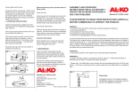
ASSEMBLY AND OPERATING
INSTRUCTIONS FOR AL-KO
SIDE LIFT JACK
2) The caravan MUST be attached to the towing vehicle and the handbrake on both the towing
vehicle and caravan MUST be applied.
3) The AL-KO Caravan Jack is not designed to be used as a permanent steady, but it can be
used as an aid to levelling the caravan, in additional to changing the wheel.
Fig 6b
4) In the case of manual towing vehicles, select 1st or reverse gear; with automatic towing
vehicles, place the selector lever in the ‘P’ position.
3. WARNING
5) As an additional safety measure, chock the caravan wheel (back and front) on the opposite
side to the one to be changed.
3.1 Never lie underneath a jacked-up vehicle,
as this is dangerous and could result in serious
injury.
TECHNICAL INFORMATION:
1) This product is suitable for use with caravans with a Maximum Gross Weight of 1600 Kg
(800 Kg static load).
2) The jack brackets can be attached to caravans fitted with AL-KO Chassis, manufactured
from 1980 onwards (drilling of the chassis required but only in accordance with the instructions
printed in this handbook).
Fig 5
3) Caravans fitted with AL-KO Chassis manufactured after 1991, already have the pre-punched
holes in the chassis frame.
AL-KO Kober Ltd
South Warwickshire Business Park
Kineton Road
Southam
Warwickshire, CV47 0AL
01926 818500 01926 818562
www.al-ko.co.uk
Part No. 1385040 Iss. 2
KIT CONTENTS:
05/02
1 x Side Lift Jack
2 x Jack Bracket
2 x M12x50 Bolt
4 x M12 Nylock Nut
1 x Storage Bag (if applicable)
4 x M13 Washer
4 x M12x25 Bolt
2 x Spacer
1. INSTALLATION OF JACK MOUNTING
BRACKETS
Fig 2
Fig 1
2.1 Attach caravan to the towing vehicle and
apply the handbrake on both towing vehicle
and caravan.
1.1 The jack mounting brackets can be fitted to
both single and tandem axle caravans, on both
sides of the chassis, behind the axle(s).
Note: Care should be taken to ensure the
brackets do not interfere with any other
equipment fitted in this area.
1.2 On AL-KO chassis manufactured from
1991 onwards, the mounting holes are already
incorporated into the longitudinal chassis
members as standard.
1.3 This jacking system can be fitted to most
AL-KO chassis manufactured from 1980
onwards.
Frame
Height
A (mm)
158
215
Hole Spacing
B (mm)
30
40
C (mm)
45
55
D (mm)
13
13
Fig 3
1.6 Drilling according to position “b” (C
Section Chassis Members)
Hole Spacing
2.5 Remove jack from storage bag (if applicable).
D (mm)
13
13
2.6 Extend spare wheel carrier (if applicable)
to remove spare wheel.
1.7 Apply corrosion protection (cold zinc
galvanising spray - CAUTION: use in well
ventilated area and follow instructions on tin).
E (mm)
30
40
F (mm)
45
55
2.4 Clean jack mounting brackets on the
caravan if necessary.
Hole Dia.
Before you start to drill the chassis members,
please note the following:
1.4.3 If the criteria in a) and b) cannot be met,
the jack mounting brackets must be fitted
behind the spare wheel carrier using holes as
shown in position “b”. Note minimum clearance dimension of 55 mm from the centre of
the spare wheel carrier mounting hole (fig 1/
item 3) to the centre of the hole for retro-fit set.
2.3 As an additional safety measure chock the
caravan wheel (back and front) on the
opposide to the one to be changed.
Hole Dia.
1.4 Drilling ‘C’ section chassis members (if
necessary)
1.4.2 The lower face of the jack mounting
bracket must hang below the lower face of the
chassis member.
2.2 In the case of manual towing vehicles,
select 1st or reverse gear; with automatic
towing vehicles, place the selector lever in the
‘P’ position.
1.5 Drilling according to position “a” (C
Section Chassis Members)
Frame
Height
A (mm)
158
215
1.4.1 When drilling in position “a” the
clearance from the rear of the wheel arch
(fig 1/item 1) to the centre of the spare wheel
carrier mounting hole (fig 1/item 2) must be a
minimum of 95 mm.
2. JACK OPERATING INSTRUCTIONS
1.8 Installation of jack mounting brackets
on high frame chassis (215 mm)
1.8.1 Position the jack mounting bracket (fig 2/
item1) with the long side on the chassis
member (fig 2/item 2) lining up the holes in
the bracket, with those in the chassis member, positioning the short side of the bracket
against the floor of the caravan.
1.8.2 Fit M13 washers (fig 2/item 4) onto
setscrews.
1.8.3 Insert setscrews M12x25 (fig 2/item 3)
through both holes with bolt heads on
outside of chassis member.
1.8.4 Fit the M12 self-locking nuts (fig 2/item
5) and torque up to 86 Nm.
1.9 Installation of jack mounting brackets
on low frame chassis (158 mm).
1.9.1 Position the jack mounting bracket (fig 3/
item 1) with the short side on the chassis
member (fig 3/item 2) in such a way that the
long side in positioned against the floor of
the caravan.
2.7 If the ground is soft or likely to giveway,
put a plank or something similar under the
base plate of the jack.
2.8 Slot the insert piece (fig 4/item 1) into the
jack mounting bracket (fig 4/item 2) until it
connects.
Fig 4
1.9.2 Fit M13 washers (fig 3/item 4) onto
setscrews.
1.9.3 Insert M12x25 (fig 3/item 3) and
M12x45 (fig 3/item 6) setscrews from the
outside.
1.9.4 Fit spacer (fig 3/item 7) onto longer bolt
before fitting to chassis.
1.9.5 Fit M12 self-locking nuts (fig 3/item 5)
and torque to 86 Nm.
2
1