1
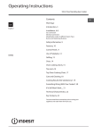
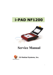
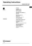
Operating Instructions COOKER Contents GB English, 1 Installation, 2-5 Positioning Electrical connection Disposal Burner and nozzle specifications Data plate Description of the appliance, 6 Overall view Start-up and use, 7-9 Hob operation Electric oven Cooking tips Precautions and tips, 10 KP9F11S/G Practical advice on using the appliance General safety Care and maintenance, 11 Switching the appliance off Cleaning the appliance Changing the oven light bulb Disassembling the oven door GB Installation GB ! Before operating your new appliance please read this instruction booklet carefully. It contains important information concerning the safe operation, installation and maintenance of the appliance. ! Please keep these operating instructions for future reference. Pass them on to possible new owners of the appliance. The following instructions are provided for qualified installers so that they may accomplish installation, adjustment and technical maintenance operations correctly and in compliance with current regulations and standards. Important: the appliance should be disconnected from the mains electricity supply before any adjustment, maintenance, etc. is carried out. Maximum caution should be used should it be necessary to keep the appliance connected to the electricity supply. The appliance has the following technical specifications: Category: II 2H3+ Positioning The dimensions of the appliance are given in the figure. For trouble-free operation of appliances installed in housing units, the minimum distances shown in figure should be observed. Adjacent surfaces and the wall at the rear should also be able to withstand an overheating temperature of 65 °C. Standards Codes Of Practice: B.S. 6172/B.S. 5440, Par. 2 and B.S. 6891 Current Editions. The following requirements must be observed: a) The cooker should not be installed in a bed sitting room with a volume of less than 20m3. If it is installed in a room of volume less than 5m3 an air vent of effective area of 110cm2 is required, if it is installed in a room of volume between 5m3 and 10m3 a supplementary airvent area of 50cm2 is required, if the volume exceeds 11m3 no airvent is required. However, if the room has a door or a window which opens directly to the outside no air vent is required even when the volume is between 5m3 and 11m3. b) During prolonged use of the appliance you may consider it necessary to open a window to the outside to improve ventilation. c) If there are other fuel burning appliances in the same room, B.S.5440 Part 2 Current Edition, should, be consulted to determine the requisite air vent requirements. Kitchen ventilation The air flow into the room where the appliance is installed must equal the quantity of air that is required for regular combustion of the gas and for ventilating the same room. Air must enter naturally through permanent apertures made in the outside walls of the room or through single or branching collective ventilation ducts in compliance with the norms. The air must be taken directly from the outside, from an area far from sources of pollution. The ventilation aperture must have the following characteristics: total free cross section of passage of at least 6 cm² for every kW of rated heating capacity of the appliance, with a minimum of 100 cm² (the heating capacity is indicated on the rating plate); it must be made in such a way that the aperture, both on the inside and outside of the wall, cannot be obstructed; it must be protected, e.g. with grates, wire mesh, etc. in such a way that the above-mentioned free section is not reduced; it must be situated as near to floor level as possible. Adjacent Room Room to be Vented A In the lower part of the cooker there are 4 height adjustable screw-in feet with which it is possible to level the cooker if necessary. Important: this unit may be installed and used only in permanently ventilated rooms according to the British 2 Examples of ventilation holes for comburant air. Enlarging the ventilation slot between window and floor. The air inflow may also be obtained from an adjoining room, provided the latter is not a bedroom or a room where there is a risk of fire, such as warehouses, garages, fuel stores, etc. and is ventilated in compliance with the norms. The air flow from the adjoining room to the one to be ventilated may pass freely through permanent apertures with a cross section at least equal to that indicated above. These apertures may also be obtained by increasing the gap between the door and the floor. If an electric fan is used for extracting the combustion products, the ventilation aperture must be increased in relation to its maximum performance. The electric fan should have a sufficient capacity to guarantee an hourly exchange of air equal to 3 ÷ 5 times the volume of the kitchen. Prolonged, intensive use of the appliance may require extra ventilation, e.g. an open window or a more efficient ventilation system by increasing the extraction power of the electric fan if installed. Liquid petroleum gas descends towards the floor as it is heavier than air. Apertures in the outside walls in rooms containing LPG cylinders should therefore be at floor level, in order to allow any gas from leaks to be expelled. Do not store LPG cylinders (even when empty) in basements or rooms below ground level; it is advisable to keep only the cylinder in use in the room at any one time and connected far from heat sources which could raise its temperature to above 50 °C. Gas supply Check that the appliance is set for the type of gas available and then connect it to the mains gas piping or the gas cylinder in compliance with the applicable norms in force. This appliance is designed and set to work with the gas indicated on the label situated on the actual hob. If the gas supply is different from the type for which the appliance has been set, replace the corresponding nozzles (provided), following the instructions given in the paragraph "Adaptation to different types of gas". For trouble-free operation, suitable use of energy and a longer life cycle for the appliance, make sure that the supply pressure complies with the values indicated in table 1 "Burner and nozzle specifications", otherwise install a special pressure regulator on the supply pipe in compliance with current standards and regulations. Connect in such a way that the appliance is subjected to no strain whatsoever. Either a rigid metal pipe with fittings in compliance with the standards in force must be used for connecting to the nipple union (threaded ½"G male fitting) situated at the rear of the appliance to the right, or flexible steel pipe in compliance with the standards in force, which must not exceed 2000 mm in length. Should it be necessary to turn the fitting, the gasket (supplied with the appliance) must be replaced. Upon completion of installation, check the gas circuit, the internal connections and the taps for leaks using a soapy solution (never a flame). Also check that the connecting pipe cannot come into contact with moving parts which could damage or crush it. Make sure that the natural gas pipe is adequate for a sufficient supply to the appliance when all the burners are lit Important: A pressure regulator, in compliance with the standards in force, must be inserted when connecting to a liquid gas supply (in a cylinder). Adapting to different types of gas To adapt the hob to a different type of gas from the factory-set one (indicated on the rating plate at the top of the hood or on the packaging), the burner nozzles should be replaced as follows: Remove the hob grids and slide the burners off their seats. Unscrew the nozzles (see figure), using a 7 mm socket spanner and replace them with nozzles for the new type of gas (see table 1 "Burner and nozzle A characteristics"). Reassemble the parts following the above procedure in the reverse order. On completing the operation, replace the old rating label with the one showing the new type of gas; the sticker is available from our Service Centres. Adjusting the primary air of the burners The primary air of the burners does not need to be adjusted. Adjusting the low flame Turn the tap to the low flame position; Remove the knob and turn the adjusting screw, situated to the right of the tap (see figure) until you obtain a regular small flame, using a screwdriver (loosening the screw increases the height of the flame, tightening decreases it). N.B.: In the case of liquid gas, the regulation screw must be screwed in all the way. 3 GB GB Having obtained the low flame setting required and with the burner lit, abruptly change the position of the knob several times from minimum to maximum and vice versa and check that the flame does not go out. In appliances fitted with the safety device (thermocouple), should the device fail to work with the burners set to the low flame setting, increase the low flame setting of the same on the adjusting screw. Once the adjustment has been made, remount the seals on the by-passes using sealing wax or similar. Electrical connection THE APPLIANCE MUST BE EARTHED The appliance is designed to work with alternating current at the supply voltage and frequency indicated on the rating plate (situated on the rear part of the appliance and on the last page of the instruction booklet) or at the end of the instruction booklet. Make sure that the local supply voltage corresponds to the voltage indicated on the rating plate. To connect directly to the mains supply, a doublepole switch with a contact separation of at least 3 mm suitable for the load and complying with current standards and regulations, must be fitted between the appliance and the mains supply outlet. The yellowgreen earth wire must not be interrupted by the switch. The supply cable must be in such a position that no part of it can reach a temperature of 50 °C above room temperature. Do not use adapters or shunts as they could cause heating or burning. Before connecting to the power supply, make sure that: the limiter valve and the domestic system can withstand the load from the appliance (see rating plate); the supply system is efficiently earthed according to standards and laws in force; the socket or double-pole switch are easily accessible when the appliance is installed. FAILURE TO OBSERVE THE ACCIDENT-PREVENTION REGULATIONS RELIEVES THE MANUFACTURER OF ALL LIABILITY. 4 Important: the wires in the mains lead are coloured in accordance with the following code: Green & Yellow Blue Brown - Earth - Neutral - Live As the colours of the wires in the mains lead may not correspond with the coloured markings identifying the terminals in your plug, proceed as follows: Connect the Green & Yellow wire to terminal marked or coloured Green or Green & Yellow. E or Connect the Brown wire to the terminal marked L or coloured Red. Connect the Blue wire to the terminal marked N or coloured Black. Replacing the cable Use a rubber cable of the type H05VV-F with a suitable cross section 3 x 1.5 mm². The yellow-green earth wire must be 2-3 cm longer than the other wires. Disposal When disposing of packaging material: observe local legislation so that the packaging may be reused. The European Directive 2002/96/EC relating to Waste Electrical and Electronic Equipment (WEEE) states that household appliances should not be disposed of using the normal solid urban waste cycle. Exhausted appliances should be collected separately in order to optimise the cost of re-using and recycling the materials inside the machine, while preventing potential damage to the atmosphere and to public health. The crossed-out dustbin is marked on all products to remind the owner of their obligations regarding separated waste collection. For further information relating to the correct disposal of exhausted household appliances, owners may contact the public service provided or their local dealer. Burner and nozzle specifications GB Table 1 Burner Liquid Gas Diameter Thermal Power By-pa(mm) kW (p.c.s.*) ss 1/100 (mm) Nom. Red. Natural Gas Nozzle 1/100 Flow* g/h Nozzler 1/100 (mm) G30/31 (mm) Flow* l/h Fast (Large) (R) 100 3.00 0.7 40 86 218 116 286 Semi Fast (Medium) (S) 75 1.65 0.4 30 64 120 96 157 Auxiliary (Small) (A) 55 1.00 0.4 30 50 73 71 95 Triple Crown (TC) 130 3.25 1.3 57 91 236 124 309 Supply pressures Nominal (mbar) Minimum (mbar) Maximum (mbar) * At 15°C and 1013 mbar-dry gas Propane G31 H.s. = 50,37 MJ/kg Butane G30 H.s. = 49,47 MJ/kg Methane G20 H.s. = 37,78 MJ/m3 28-30 20 35 20 17 25 DATA PLATE Dimensions HxWxD 32x54x38 cm Volume 68 l Burners may be adapted for use with any type of gas shown on the data plate Electrical connections voltage: 220-240V ~ 50/60Hz maximum power absorbed 2400W Directive 2002/40/EC on the label of electric ovens Norm EN 50304 ENERGY LABEL Declared energy consumption for Natural convection Class – heating mode: Static This appliance conforms to the following European Economic Community directives: 2006/95/EEC of 12/12/06 (Low Voltage) and subsequent amendments; - 89/336/EEC of 03/05/89 (Electromagnetic Compatibility) and subsequent amendments; - 93/68/EEC of 22/07/93 and subsequent amendments. - 2002/96/EC 5 Description of the appliance Overall view SUPPORT GRID SEMI-RAPID GAS BURNER RAPID TRIPLE RING GAS BURNER SEMI-RAPID GAS BURNER PAN REDUCING SUPPORT AUXILIARY GAS BURNER CONTROL KNOBS FOR GAS BURNERS TIMER KNOB (cooking programmer) IGNITION PUSHBUTTON FOR GAS BURNERS ELECTRIC OVEN THERMOSTAT KNOB (temperature selection) ELECTRIC OVEN SELECTOR KNOB (cooking function selection) ELECTRIC OVEN OPERATION INDICATOR LIGHT 20 mm Ignition for GAS BURNERS * SAFETY DEVICES * * Only available on certain models. 6 120 - 180 mm GB Start-up and use Hob operation The burners are fitted with automatic ignition and a thermocouple safety device, which automatically cuts off the gas from the burner in a few seconds if the flame accidentally goes out during operation. The burners differ in size and power. Choose the most appropriate one for the diameter of the cookware being used. Each burner can be regulated with the corresonding control knob by using one of the following settings: Off High flame Low flame The symbols n , near the knobs show the position of the relative burner on the hob. Using the burners: To obtain maximum efficiency from the burners, it is advisable to only use pans with a diameter suitable for the burner being used, so that the flame does not extend beyond the pan base (see following table). When a liquid starts boiling, it is advisable to turn the flame down just enough to keep the liquid simmering. Burner ø Cookware Diameter (cm) Fast (R) 24 - 26 Semi Fast (S) 16 - 20 Auxiliary (A) 10 - 14 Triple Crown (TC) 24 - 26 The hob is fitted with reducing pan stands, which should only be used on auxiliary burner "A". To ignite a burner, proceed as follows: turn the relative knob counter-clockwise until the pointer is on the high-flame symbol; press the knob down fully and activate the automatic gas ignition by pushing at the same time the button marked with the symbol ; keep the knob pressed down for about 10 seconds with the flame lit to allow the safety thermocouple to be heated; release the knob, checking that the flame is stable. If it is not, repeat the operation. For minimum power, turn the knob towards the low flame symbol. Intermediate positions are possible by simply putting the knob anywhere between the high and the low flame symbol. To turn off the burner, turn the knob clockwise to the off position " " . Important: Do not activate the automatic ignition device for more than 15 consecutive seconds. Difficulty in ignition is sometimes due to air inside the gas duct. If a burner flame accidentally goes out, the gas continues to exit for a few moments before the safety device activates. Turn the control knob to the off position and do not attempt ignition again for at least 1 minute, thereby letting the gas disperse, which could otherwise be a danger. When the appliance is not in operation, check that the knobs are in the off position " " . The main gas supply cut-off cock should also be closed. ELECTRIC OVEN The maxi-oven gives four combinations of heating elements; so the most suitable type of cooking for each dish may therefore be chosen, with convincing results. By turning the knob of the selector switch marked , different cooking functions are with the symbol obtained, as shown in the following table: Symbol 0 Function 0) Off Power - 1) Top + Bottom heating elements 2350 W 2) Bottom heating element 1300 W 3) Top heating element 1050 W 4) Grill heating element 2000 W After having selected the heat source, put the thermostat knob (marked with the symbol ) to the temperature required. For normal cooking (roasts, biscuits, etc.) in conventional mode use the function (hot above+below). Only put the food to be cooked into the oven when it has reached the selected temperature and preferably use just one shelf for cooking. 7 GB GB To provide heat only to the bottom or the top part of the dishes, turn the selector to the position (hot below) or (hot above); Grill operation: a high heat output is used for grilling, so that the surface of the food is immediately browned; this is particularly indicated for meats which should remain tender inside. To grill, turn the selector knob to the position (grill). During grilling, do not set the thermostat knob to over 200 °C and keep the oven door closed. Minute minder To use the timer, you must wind the alarm by turning the knob almost one complete turn clockwise; then turn the knob back to set the time by positioning the minutes required on the index of the facia. 8 Oven light The oven light comes on automatically when the selector knob is turned to any of its positions. Indicator light It indicates that the oven is heating up. When the light goes out, the required temperature has been reached inside the oven. When the light alternately comes on and goes out, it means that the thermostat is working properly to maintain the oven temperature. Cooking tips GB Cooking times may vary according to the nature of the foods, their homogeneity and their volume. When cooking a certain food for the first time, it is advisable to choose the lowest values in the cooking time range given in the table and then increase them if necessary. CONVENTIONAL oven cooking Type of dish Temperature °C Cooking time (minutes) Pastries and cakes Fruit pie Meringues Sponge cake Angel cake Madeira cake Chocolate cake Flat sweet loaf Puffs Flaky pastry biscuits Mille feuilles Short crust pastry 130 130 150 160 160 170 170 200 200 200 200 60-70 30-40 20-30 40-50 40-50 30-40 40-50 15-20 15-20 15-20 15-20 Type of dish Temperature °C Cooking time (hours) Meat Turkey (4-8 kg) Goose (4-5 kg) Duck (2-4 kg) Capon (2½-3 kg) Braised beef (1-1½ kg) Leg of lamb Roast hare (2 kg) Roast pheasant Chicken (1-1½ kg) 160 160 170 170 160 160 160 160 170 3-4½ 4-4½ 1½-2½ 2-2½ 3-3½ 1-1½ 1-1½ 1-1½ 1-1½ Fish 200 15-25 minutes GRILLING Type of dish Cooking time (minutes) Position of shelf Chops (0.5 kg) Saussages Grilled chicken (1 kg) Veal on the spit (0.6 kg) Chicken on the spit (1 kg) 60 15 60 60 60 3rd guide rail 2nd guide rail 1st guide rail - The 1st guide rail is understood as being the lowest position. Notes: 1) Cooking times do not include oven pre-heating, except for those marked with an asterisk. 2) The indication given in the table for the guide rails is the one that should preferably be used in the event of cooking on more than one level. 3) The indicated times refer to cooking on one shelf only; for cooking on more than one level, increase the time by 5 ÷ 10 minutes. 4) For roast beef, veal, pork and turkey, on the bone or rolled, increase the times by 20 minutes. 9 Precautions and tips GB This appliance has been designed and manufactured in compliance with international safety standards. The following warnings are provided for safety reasons and must be read carefully. General safety The appliance was designed for domestic use inside the home and is not intended for commercial or industrial use. The appliance must not be installed outdoors, even in covered areas. It is extremely dangerous to leave the appliance exposed to rain and storms. Do not touch the appliance with bare feet or with wet or damp hands and feet. The appliance must be used by adults only for the preparation of food, in accordance with the instructions provided in this booklet. The instruction booklet accompanies a class 1 (insulated) or class 2 - subclass 1 (recessed between 2 cupboards) appliance. Do not touch the heating elements or certain parts of the oven door when the appliance is in use; these parts become extremely hot. Keep children well away from the appliance. Make sure that the power supply cables of other electrical appliances do not come into contact with the hot parts of the oven. The openings used for the ventilation and dispersion of heat must never be covered. Always use oven gloves when placing cookware in the oven or when removing it. Do not use flammable liquids (alcohol, petrol, etc...) near the appliance while it is in use. Do not place flammable material in the lower storage compartment or in the oven itself. if the appliance is switched on accidentally, they could catch fire. The internal surfaces of the compartment (where present) may become hot. Always make sure the knobs are in the position when the appliance is not in use. When unplugging the appliance, always pull the plug from the mains socket; do not pull on the cable. Never perform any cleaning or maintenance work without having disconnected the appliance from the electricity mains. 10 If the appliance breaks down, under no circumstances should you attempt to perform the repairs yourself. Repairs carried out by inexperienced persons may cause injury or further malfunctioning of the appliance. Contact Assistance. Do not rest heavy objects on the open oven door. The appliance should not be operated by people (including children) with reduced physical, sensory or mental capacities, by inexperienced individuals or by anyone who is not familiar with the product. These individuals should, at the very least, be supervised by someone who assumes responsibility for their safety or receive preliminary instructions relating to the operation of the appliance. Do not let children play with the appliance. If the cooker is placed on a pedestal, take the necessary precautions to prevent the same from sliding off the pedestal itself. Disposal When disposing of packaging material: observe local legislation so that the packaging may be reused. The European Directive 2002/96/EC relating to Waste Electrical and Electronic Equipment (WEEE) states that household appliances should not be disposed of using the normal solid urban waste cycle. Exhausted appliances should be collected separately in order to optimise the cost of re-using and recycling the materials inside the machine, while preventing potential damage to the atmosphere and to public health. The crossed-out dustbin is marked on all products to remind the owner of their obligations regarding separated waste collection. For further information relating to the correct disposal of exhausted household appliances, owners may contact the public service provided or their local dealer. Respecting and conserving the environment You can help to reduce the peak load of the electricity supply network companies by using the oven in the hours between late afternoon and the early hours of the morning. Always keep the oven door closed when using the GRILL modes: This will achieve improved results while saving energy (approximately 10%). Check the door seals regularly and wipe them clean to ensure they are free of debris so that they adhere properly to the door, thus avoiding heat dispersion. Care and maintenance Switching the appliance off Disconnect your appliance from the electricity supply before carrying out any work on it. Cleaning the appliance Do not use abrasive or corrosive detergents (for example, products in spray cans for cleaning barbecues and ovens), stain removers, anti-rust products, powder detergents or sponges with abrasive surfaces: these may scratch the surface beyond repair. Never use steam cleaners or pressure cleaners on the appliance. Disassembling/assembling the oven door To make it easier to clean the inside of your oven, the oven door can be removed, by proceeding as follows: Open the door completely and lift the 2 levers B; Now, shutting the door slightly, you can lift it out by pulling out the hooks A as shown in figure. To reassemble the door: With the door in a vertical position, insert the two hooks A into the slots; Ensure that seat D is hooked perfectly onto the edge of the slot (move the oven door backwards and forward slightly); Keep the oven door open fully, unhook the 2 levers B downwards and then shut the door again. To extend the life of your oven, it must be cleaned frequently, keeping in mind that: The self-cleaning panels (if present) and the enameled parts should be washed with warm water - abrasive powders and corrosive substances should be avoided; The inside of the oven should be cleaned immediately after use with warm water and soap; the soap should be rinsed away and the interior dried thoroughly; Stainless steel can be stained if it remains in contact with agressive detergents (containing phosphorus) or water with a high lime content. We recommend that you rinse these parts thoroughly and dry them well after cleaning. It is also a good idea to dry any water spills; Never line the bottom of the oven with aluminium foil because the buildup of heat will not only impede the cooking process, but could also damage the enamel. Changing the oven light bulb Cutoff the supply of power to the oven by turning off the omni-polar switch connecting it to the mains, or by removing the plug if it is accessible; Unscrew the glass cover attached to the lamp holder; Unscrew the lamp and replace it with another hightemperature lamp (300°C) with the following characteristics: - Voltage: 230/240 V - Wattage: 15W - Socket: E14 Remount the glass cover and reconnect the appliance to the power supply. 11 GB 12/2008 - 195070160.00 XEROX FABRIANO GB 12