Transcript
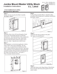
7920 - OPERATING INSTRUCTIONS
Introduction
The UHF Contact Operated Transmitter has been designed to be used with both the System 1000 IRIS
7256 and Single Way 7703 receiver units. The transmitter is a UHF transmitter working at 458 MHz with
an output power of less than 1mW. The transmitter operates both as a normally closed (N/C) or normally
open (N/O) device. Alarm signals are generated at each change of state of the transmitter input.
The Transmitter
The transmitter is mounted in a moulded enclosure measuring 100mm x 62mm x
20mm. Cable access is via knockouts on the rear and top of the enclosure. The unit
is powered by a 6V alkaline battery. Battery life depends upon how often the
transmitter is used. For average usage the battery will last in excess of 12 months.
Figure 1 shows the contact transmitter with the key inserted this is necessary to
enable the removal of the wall mounting/connection plate. Ensure access is available
for the key after installation of plate.
Figure 1
The Wall mounting / connection plate should be screwed to the wall using
suitable fixings ensuring the tamper knockout is cut from the moulding and
screwed to the wall for rear tamper protection as shown in figure 2.
Figure 3 shows the contact side of the transmitter. Cable connections are
made between the screw terminals as shown and then connected to the two
way terminal block fitted on the wall mounting plate.
Before fitting the unit to its wall mounting / connection plate ensure the 6v
battery is connected into the battery compartment as shown in figure 4.
When fitting the transmitter into its bracket ensure that it is clipped in
firmly. A click should heard once the unit is installed into the bracket.
Figure 2
Test Mode
The contact transmitter terminal connections can be tested
without the use of the main control panel.
Press and release the test button shown in figure 4 the red light
will flash on the front of the unit to indicate test mode.
Operation of the contact will make the light flash at a different
rate confirming the correct connectivity.
Resistor Colours
2K2 = Red Red Red
4K7 = Yellow Violet Red
Figure 3
The unit will automatically return to normal operation mode after
a minute.
Battery Replacement
After replacing the batteries, it is recommended that the device is tested to
ensure the batteries have been inserted correctly and the device has been
returned to a fully operational condition.
Figure 4