1
EG1–293
3S–GTE ENGINE
–
SMPI SYSTEM
TROUBLESHOOTING WITH VOLT OHMMETER
HINT:
•
The following troubleshooting procedures are designed for inspection of each separate system,
and therefore the actual procedure may vary somewhat. However, troubleshooting should be
performed while referring to the inspection methods described in this manual.
•
Before beginning inspection, it is best to first make a simple check of the fuses, H–fuses, fusible
link and the condition of the connectors.
•
The following troubleshooting procedures are based on the supposition that the trouble lies in
either a short or open circuit within the computer.
•
If engine trouble occurs even though proper operating voltage is detected in the computer
connector, then it can be assumed that the PCME is faulty and should be replaced.
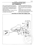
FUSES, H– FUSES AND FUSIBLE LINK LOCATION
EG1–294
3S–GTE ENGINE
–
SMPI SYSTEM
SMPI SYSTEM CHECK PROCEDURE
PREPARATION
(a) Disconnect the connectors from the PCME.
(b) Remove the locks as shown in the illustration so that
the tester probe(s) can easily come in.
NOTICE: Pay attention to sections ’A’ and ’B’ in the
Illustration which can be easily broken.
(c) Reconnect the connectors to the PCME.
HINT:
•
Perform all voltage measurements with the con–
nectors connected.
•
Verify that the battery voltage is 11 V or more
when the ignition switch is in the ”ON” position.
Using a voltmeter with high impedance (10 k/V
minimum), measure the voltage at each terminal of
the wiring connectors.
EG1–295
3S–GTE ENGINE
–
SMPI SYSTEM
PCME Wiring Connectors Voltage
No.
Condition
Terminals
lGS WON
Throttle valve open
STD voltage (V)
See page
9–14
EG1–296
9–14
EG1–297
9–14
4.5–5.5
IG SW ON
EG1–298
Throttle valve fully closed
(Throttle opener must be cancelled first)
0.3–0.8
Throttle valve fully open
3.2–4.9
4.5–5.5
Measuring plate fully closed
4.0–5.5
Measuring plate fully open
0.2–0.5
EG1–300
Idling
1.6–4.1
3,000 rpm
1.0–2.0
IG SW ON
9–14
EG1–301
Intake air temp. 20°C (68°F)
0.5–3.4
EG1–302
Coolant temp. 80°C (176°F)
0.2–1.0
EG1–303
6 or more
EG1–304
Pulse generation
EG1–305
9–14
EG1–306
9–14
EG1 –307
IG SW ON
Cranking
Idling
IG SW ON
PCME connectors disconnected
No trouble (”CHECK” engine warning light off) and engine
running
2.5–4.5
EG1–308
IG SW ON
4.5–5.5
IG SW ON
PCM E Terminals
Air conditioning ON
9–14
EG1–309
EG1–296
3S–GTE ENGINE
No.
Terminals
–
SM PI SYSTEM
Trouble
Condition
STD voltage
No voltage
IG SW ON
9–14V
1 There is no voltage between PCME terminals + B or + B1 and E1.
(IG SW ON)
2 Check that there is voltage between PCME terminal + B or + B1
and body ground. (IG SW ON)
3 Check wiring between PCME terminal E1 and body
ground.
BAD
Try another PCM E.
Repair or replace.
Check fuses, N–fuse, fusible link and
ignition switch.
BAD
Check M PI main relay.
(See page EG1–374)
BAD
Check wiring between MPI main
relay and battery.
BAD
Repair or replace.
Replace.
Repair or replace.
EG1–297
3S–GTE ENGINE
No.
Terminals
Trouble
–
SMPI SYSTEM
Condition
STD voltage
No voltage
9–14V
1 There is no voltage between PCME terminals BATT and E1.
2 Check that there is voltage between PCME terminal BATT and
body ground.
3 Check wiring between PCME terminal E1 and body
ground.
BAD
Repair or replace.
Try another PCME.
Check fuse, H–fuse and fusible link.
Check wiring between PCME terminal
and battery.
BAD
BAD
Replace.
Repair or replace.
EG1–298
3S–GTE ENGINE
No.
Terminals
–
Trouble
SMPI SYSTEM
STD voltage
Condition
Throttle valve open
No voltage
Throttle valve fully closed
Throttle opener must be
cancelled first
IG SW ON
Throttle valve fully open
• IDL – E2
There is no voltage between PCME terminals IDL and E2.
(IG SW ON) (Throttle valve open)
Check that there is voltage between PCME terminal + B (+ B1)
and body ground. (IG SW ON)
Check wiring between PCME terminal E1 and body ground.
BAD
Repair or replace.
Try another PCM E.
Refer to No. 1.
(See page EG1–296)
BAD
Repair or replace.
Check throttle position sensor.
(See page EG1–362)
BAD
BAD
Repair or replace
throttle position sensor.
Check wiring between PCME and
throttle position sensor.
Try another PCME.
EG1–299
3S–GTE ENGINE
–
SMPI SYSTEM
• VC–E2
There is no voltage between PCME terminals VC and E2.
(IG SW ON)
Check that there is voltage between PCME terminal + B
(+ B1) and body ground. (IG SW ON)
Refer to No. 1.
(See page EG1–296)
Check throttle position sensor.
(See page EG1–362)
BAD
Repair or replace.
Check wiring between PCM E and throttle
position sensor.
BAD
Repair or replace
wiring.
Try another PCM E.
• VTA – et
There is no specified voltage at PCME terminals VTA and E2.
(IG SW ON)
Check that there is voltage between PCME terminals VC and E2.
(IG SW ON)
Refer to VC – E2 trouble
section.
Check throttle position sensor.
(See page EG1–362)
Check wiring between PCME and
throttle position sensor.
Try another PCME.
BAD
Repair or replace.
BAD
Repair or replace.
EG1–300
3S–GTE ENGINE
No.
Terminals
–
Trouble
SMPI SYSTEM
Condition
IG SW ON
No voltage
STD voltage
Measuring plate fully closed
Measuring plate fully open
Idle
3,000 rpm
1 There is no specified voltage at PCM E terminals VC or VS and E2.
(IG SW ON)
2 Check that there is voltage between PCM E terminal + B (+ 131) and
body ground. (IG SW ON)
Refer to No. 1.
(See page EG1–296)
Check wiring between PCME terminal E1 and body ground.
BAD
3 Check air flow sensor.
(See page EG1–358)
Repair or replace.
BAD
Repair or replace
air flow sensor.
Check wiring between PCM E and
air flow sensor.
BAD
Try another PCM E.
Repair or replace.
EG1–301
3S–GTE ENGINE
No.
Terminals
–
SMPI SYSTEM
Trouble
Condition
No voltage
IG SW ON
STD voltage
There is no voltage between PCME terminals #1, #2, #3 and/or
#4 and E01 and/or E02. IG SW ON)
Check that there is specified voltage between solenoid resistor
terminal + B and body ground. STD voltage: 9 –14 V
Check fuse, H–fuse, fusible link, wiring,
ignition switch and ignition main relay.
BAD
Repair or
replace.
Check resistance between +B of solenoid resistor and each other
terminal. STD resistance: 4 – 6
Check resistance of each injector.
STD resistance: 2 – 4
Replace
resistor.
OK
BAD
Replace injector.
Check wiring between PCME and
resistor
Try another PCME.
BAD
Repair or replace
wiring.
EG1–302
3S–GTE ENGINE
No.
Terminals
No voltage
–
SMPI SYSTEM
Trouble
Condition
IG SW ON
STD voltage
Intake air temperature 20°C
168oF/
There is no voltage between PCME terminals THA and E2.
(IG SW ON)
Check that there is voltage between PCME terminal + B (+ 131) and
body ground. (IG SW ON)
Refer to No.1.
(See page EG1–296)
Check wiring between PCME terminal E1 and body ground.
BAD
Check intake air temp. sensor
(See page EG1–358)
Repair or replace.
BAD
Replace air flow
sensor.
Check wiring between PCME and intake
air temp. sensor
BAD
Try another PCME.
Repair or replace.
EG1–303
3S–GTE ENGINE
No.
Terminals
–
STD voltage
Condition
Trouble
No voltage
SMPI SYSTEM
IG SW ON
Coolant temperature 80°C (176°F)
There is no voltage between PCME terminals THW and E2.
(IG SW ON)
Check that there is voltage between PCME terminal + B
(+ B1) and body ground. (IG SW ON)
Refer to No.1.
(See page EG1–296)
Check wiring between PCME terminal E1 and body ground.
BAD
Check engine coolant temp. sensor.
(See page EG1–378)
Repair or replace.
BAD
Replace engine coolant
temp. sensor.
Check wiring between PCME and engine
coolant temp. sensor.
BAD
Try another PCME.
Repair or replace.
EG1–304
3S–GTE ENGINE
No.
Terminals
–
SMPI SYSTEM
Trouble
Condition
No voltage
Cranking
STD voltage
There is no voltage between PCME terminals STA and El.
(IG SW ON)
Check starter
operation.
Check wiring between PCME terminal STA
and ignition switch terminal ST2.
BAD
BAD
Repair or replace.
Check wiring between PCME terminal E1 and body
ground.
BAD
Repair or replace.
Try another PCME.
Check fuse, H–fuse, fusible link,
battery, wiring, ignition switch, clutch
start switch and starter relay.
BAD
Repair or replace.
Check that there is voltage at starter terminal 50.
(IG SW START) STD voltage: 6 V or more
Check starter.
Check wiring between ignition switch
terminal ST2 and starter terminal 50.
EG1–305
3S–GTE ENGINE
No.
Terminals
–
SMPI SYSTEM
Trouble
Condition
No voltage
Idling
STD voltage
1 There is no voltage between PCME terminals IGT and E1.
(Idling)
2 Check that there is voltage between PCME terminal IGT and body
ground. (idling)
BAD
~ Check wiring between PCME
terminal E1 and body ground.
Repair or
Replace.
Try another PCME.
Check fuse, H–fuse, fusible link, ignition
switch and ignition main relay.
Check distributor. (See IG section)
Check wiring between PCME and
battery.
Check igniter. (See IG section)
BAD
Repair or replace.
BAD
Repair or replace.
BAD
Repair or replace.
BAD
Repair or replace.
EG1–306
3S–GTE ENGINE
No.
Terminals
SMPI SYSTEM
STD voltage
Condition
Trouble
No voltage
–
IG SW O N
PCME connecters disconnected
There is no voltage between PCME terminals RSC or RSO and E1.
(IG SW ON)
Check that there is voltage between PCME terminal + B (+ B1)
and body ground. (IG SW ON)
Refer to No–1 .
(See page EG1–296)
Check resistance between IACV
terminals + B and RSC or RSO.
STD resistance: 17.7 – 23.9 0
Check wiring between PCME and
IACV.
Try another PCME.
BAD
Replace IACV.
BAD
Repair or replace
wiring.
EG1–307
3S–GTE ENGINE
No.
Terminals
Trouble
No voltage
–
SMPI SYSTEM
Condition
STD voltage
No trouble (”CHECK” engine warning light off)
and engine running.
There is no voltage between PCME terminals W and E1.
(Idling)
Check that there is voltage between PCME terminal w and body
ground.
Check wiring between PCME terminal E1 and body
ground.
BAD
Try another PCME.
Repair or replace.
Check fuse GAUGE
(7.5 A) and check engine warning light.
BAD
Repair or replace.
Fuse blows again
Check wiring between PCME
terminal W and fuse.
BAD
Repair or replace.
EG1–308
3S–GTE ENGINE
No.
Terminals
–
SMPI SYSTEM
Trouble
Condition
No voltage
IG SW ON
STD voltage
There is no voltage between PCME terminals PlM or VC and E2.
(IG SW ON)
Check that there is voltage between PCME terminal + B or + 131
and body ground. OG SW ON)
Refer to No.1.
(See page EG1–296)
Check wiring between PCME terminal E1 and body ground.
BAD
Check manifold absolute pressure
sensor. (See page EG1–400)
Repair or replace.
BAD
Replace manifold
absolute pressure sensor.
Check wiring between PCME and
manifold absolute pressure sensor.
BAD
Try another PCME.
Repair or replace.
EG1–309
3S–GTE ENGINE
No.
Terminals
–
STD voltage
Condition
Trouble
No voltage
SMPI SYSTEM
Air conditioning ON
1 There is no voltage between PCME terminals AC and E1.
Air conditioning ON)
2 Check that there is voltage between PCME terminal AC and body
ground.
3 Check wiring between PCME terminal E1 and body
ground.
BAD
Repair or replace.
Try another PCME.
Check wiring
between PCME
terminal AC and
amplifier.
Check compressor running.
BAD
BAD
Repair or replace.
Check that there is voltage between
amplifier terminal and body ground.
BAD
Repair or replace.
BAD
Check wiring between amplifier and
PCME or compressor.
Repair or replace.
EG1–310
3S–GTE ENGINE
–
SMPI SYSTEM
There is no voltage between PCME terminals VF and E1.
Check that there is specified voltage between PCME terminals VF and
body ground.
OK
Check wiring between PCME terminal E1 and body ground.
BAD
OK
Repair
or replace.
Try another PCME.
BAD
Check for air suction into exhaust system.
OK
BAD
Check for air leak from air intake system. BAD
BAD
OK
Check spark plugs.
OK
Check distributor and ignition system.
BAD
OK
BAD
Check fuel pressure.
BAD
OK
BAD
Check injectors.
OK
OK
Repair air suction.
Repair air leak.
Repair or replace.
Repair or replace.
Repair or replace.
Repair or replace.
Check cold start injector.
OK
Check air flow sensor.
OK
Repair or replace.
Check operation of oxygen sensor.
BAD
System normal
Check wiring between oxygen sensor
and PCME connectors.
Replace oxygen sensor.
Repair or replace.
BAD
Repair wiring.
* Rich malfunction only
EG1–311
3S–GTE ENGINE
–
SMPI SYSTEM
There is no voltage between PCME terminals THG and E2.
(IG SW ON)
Check that there is voltage between PCME terminal + B or + 81
and body ground. (IG SW ON)
Refer to No.1.
(See page EG1–296)
Check wiring between PCME terminal E1 and body ground.
BAD
Repair or replace.
BAD
Check EGR system
(See page EG1–243)
Repair or replace.
Check EGR function
sensor. (See page EG1–402)
BAD
Replace EGR function
sensor.
Check wiring between PCME and EG R
function sensor.
BAD
Try another PCME.
Repair or replace.