1
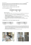
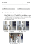
Bruker Elektronik GmbH nfo 26.01.2010 Operating instructions for the probe PH MASDVT850W6 BL3.2 X/Y/H DBB (H13857/0001) The probe is delivered in λ/4 mode 1. Listing of the included X/Y stop circuit coil Coil with 2.5 turns λ/2 - mode λ/4 - mode f/MHz f/MHz 190 – 268 117 – 164 / 131 – 196 + 22pF serial C 180 – 217 85 – 143 / 86 – 151 X range Y range f/MHz f/MHz + 22pF serial C 162 – 265 80 – 129 / 116 – 179 + 22pF serial C 145 – 214 76 – 121 / 78 – 140 Coil with 6.5 turns λ/2 - mode λ/4 - mode Y range + 22pF serial C Coil with 4.5 turns λ/2 - mode λ/4 - mode X range X range Y range f/MHz f/MHz + 22pF serial C 177 – 263 77 – 110 / 105 – 163 + 22pF serial C 125 – 214 67 – 106 / 72 – 134 1. Changing the stop circuit coil 1. 2. 3. 4. 5. Unscrew (but don’t remove) 4 screws at the flange of the shielding tube and remove the tube. Unscrew the two M2.5-fixing screws (Fig. 1 below) and remove the installed stop circuit coil and change it by a disered one. Install the new coil in the opposite way; do not tighten the screws too much. To adjust the optimize stop circuit frequency it is necessary to use a Network-Analyzer and connect it between X and Y- channel at the probe (reflection X-connector; transmission Y-connector), see fig.2 below Slide on the shielding tube and lock it. First tune and match 1H, then X and at last Y-channel. Repeat this procedure for fine tuning. Fixing screws transmission reflection Fig.1 Position of the stop circuit coil Fig.2 probe connectors 50Ω load 2. Changing between λ/2- and λ/4-mode 1. 2. In case of operating in λ/2-mode, frequency range see list, it is necessary to remove the short circuit screw (at the /2-tube of the 1H-channel, see Fig.3, below). In the other case in λ/4-mode, frequency range see list, use the marker at the /2-tube and carefully turn in the screw equally and continously until one has contact with the inner conductor of the /2-line. Do not turn this screw too far in order to avoid bending or damage of the inner conductor. Slide on the shielding tube and lock it. First tune and match 1H, and then X and Y. Repeat this procedure for fine tuning. Fig.3 screw out λ/2-mode Fig.4 screw in λ/4-mode 2. Adjustment for Optimization of the stop circuit frequency 1. Adjust the stop circuit frequency by turning the black rod at the bottom of the probe, see Fig.5 and observe the insolation at the Network- Analyzer, see Fig.6 and Fig.7 Stop circuit Adjustment rod Fig.5 Adjustment rod of the stop circuit frequency Fig.6 13C stop circuit frequency not optimized Fig.7 13C stop circuit frequency optimized