1
Operating Instructions
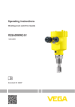
VEGASWING 63
- contactless electronic switch
Document ID:
29228
Vibration
Contents
Contents
1
About this document
1.1
1.2
1.3
2
.
.
.
.
.
.
.
.
.
.
.
.
.
.
.
.
.
.
.
.
.
.
.
.
.
.
.
.
.
.
.
.
.
.
.
.
.
.
.
.
.
.
.
.
.
.
.
.
.
.
.
.
.
.
.
.
.
.
.
.
.
.
.
.
.
.
.
.
.
.
.
.
..
..
..
..
..
..
..
..
..
5
5
5
5
6
6
6
6
6
.
.
.
.
.
.
.
.
.
.
.
.
.
.
.
.
.
.
.
.
.
.
.
.
.
.
.
.
.
.
.
.
.
.
.
.
.
.
.
.
.
.
.
.
.
.
.
.
.
.
.
.
.
.
.
.
..
..
..
..
7
8
9
9
General instructions . . . . . . . . . . . . . . . . . . . . . . . . .
Mounting instructions . . . . . . . . . . . . . . . . . . . . . . . .
10
13
Structure . . . . . . . . . .
Principle of operation .
Operation. . . . . . . . . .
Storage and transport
.
.
.
.
.
.
.
.
.
.
.
.
.
.
.
.
.
.
.
.
.
.
.
.
.
.
.
.
Preparing the connection . . . . . . . . . . . . . . . . . . . . .
Connection procedure. . . . . . . . . . . . . . . . . . . . . . . .
Wiring plan, single chamber housing . . . . . . . . . . . . .
17
17
18
General . . . . . . . . . . . . . . . . . . . . . . . . . . . . . . . . . .
Adjustment elements . . . . . . . . . . . . . . . . . . . . . . . .
Functional chart . . . . . . . . . . . . . . . . . . . . . . . . . . . .
21
21
22
..
..
..
..
24
24
25
26
Dismounting steps . . . . . . . . . . . . . . . . . . . . . . . . . .
Disposal . . . . . . . . . . . . . . . . . . . . . . . . . . . . . . . . .
27
27
Maintenance . . . . . . . . . . .
Rectify faults . . . . . . . . . . .
Exchange of the electronics
Instrument repair . . . . . . . .
.
.
.
.
.
.
.
.
.
.
.
.
.
.
.
.
.
.
.
.
.
.
.
.
.
.
.
.
.
.
.
.
.
.
.
.
.
.
.
.
.
.
.
.
.
.
.
.
.
.
.
.
.
.
.
.
.
.
.
.
.
.
.
.
.
.
.
.
Technical data . . . . . . . . . . . . . . . . . . . . . . . . . . . . .
28
VEGASWING 63 • - contactless electronic switch
29228-EN-100805
Supplement
9.1
2
.
.
.
.
.
.
.
.
.
Dismounting
8.1
8.2
9
.
.
.
.
.
.
.
.
.
Maintenance and fault rectification
7.1
7.2
7.3
7.4
8
.
.
.
.
.
.
.
.
.
Set up
6.1
6.2
6.3
7
.
.
.
.
.
.
.
.
.
Connecting to power supply
5.1
5.2
5.3
6
.
.
.
.
.
.
.
.
.
Mounting
4.1
4.2
5
.
.
.
.
.
.
.
.
.
Authorised personnel . . . . . . . .
Appropriate use . . . . . . . . . . . .
Warning about misuse . . . . . . .
General safety instructions . . . .
Safety label on the instrument . .
CE conformity . . . . . . . . . . . . .
SIL conformity . . . . . . . . . . . . .
Safety instructions for Ex areas .
Environmental instructions. . . . .
Product description
3.1
3.2
3.3
3.4
4
4
4
4
For your safety
2.1
2.2
2.3
2.4
2.5
2.6
2.7
2.8
2.9
3
Function. . . . . . . . . . . . . . . . . . . . . . . . . . . . . . . . . .
Target group . . . . . . . . . . . . . . . . . . . . . . . . . . . . . .
Symbolism used. . . . . . . . . . . . . . . . . . . . . . . . . . . .
Contents
9.2
Dimensions . . . . . . . . . . . . . . . . . . . . . . . . . . . . . . .
35
Supplementary documentation
Information:
Supplementary documents appropriate to the ordered version come
with the delivery. You can find them listed in chapter "Product
description".
Instructions manuals for accessories and replacement parts
29228-EN-100805
Tip:
To ensure reliable setup and operation of your VEGASWING 63, we
offer accessories and replacement parts. The corresponding documentations are:
l
l
l
l
l
30173
34296
29750
29751
29752
-
Electronics module VEGASWING series 60
Protective cover
Lock fitting for VEGASWING 63 unpressurized
Lock fitting for VEGASWING 63 16 bar
Lock fitting for VEGASWING 63 64 bar
VEGASWING 63 • - contactless electronic switch
3
1 About this document
1 About this document
1.1 Function
This operating instructions manual provides all the information you
need for mounting, connection and setup as well as important
instructions for maintenance and fault rectification. Please read this
information before putting the instrument into operation and keep this
manual accessible in the immediate vicinity of the device.
1.2 Target group
This operating instructions manual is directed to trained qualified
personnel. The contents of this manual should be made available to
these personnel and put into practice by them.
1.3 Symbolism used
Information, tip, note
This symbol indicates helpful additional information.
Caution: If this warning is ignored, faults or malfunctions can
result.
Warning: If this warning is ignored, injury to persons and/or serious
damage to the instrument can result.
Danger: If this warning is ignored, serious injury to persons and/or
destruction of the instrument can result.
Ex applications
This symbol indicates special instructions for Ex applications.
l
à
1
List
The dot set in front indicates a list with no implied sequence.
Action
This arrow indicates a single action.
Sequence
Numbers set in front indicate successive steps in a procedure.
29228-EN-100805
4
VEGASWING 63 • - contactless electronic switch
2 For your safety
2 For your safety
2.1 Authorised personnel
All operations described in this operating instructions manual must be
carried out only by trained specialist personnel authorised by the plant
operator.
During work on and with the device the required personal protective
equipment must always be worn.
2.2 Appropriate use
The VEGASWING 63 is a sensor for level detection.
You can find detailed information on the application range in chapter
"Product description".
Operational reliability is ensured only if the instrument is properly used
according to the specifications in the operating instructions manual as
well as possible supplementary instructions.
For safety and warranty reasons, any invasive work on the device
beyond that described in the operating instructions manual may be
carried out only by personnel authorised by the manufacturer. Arbitrary
conversions or modifications are explicitly forbidden.
2.3 Warning about misuse
Inappropriate or incorrect use of the instrument can give rise to
application-specific hazards, e.g. vessel overfill or damage to system
components through incorrect mounting or adjustment.
2.4 General safety instructions
This is a high-tech instrument requiring the strict observance of
standard regulations and guidelines. The user must take note of the
safety instructions in this operating instructions manual, the countryspecific installation standards as well as all prevailing safety
regulations and accident prevention rules.
29228-EN-100805
The instrument must only be operated in a technically flawless and
reliable condition. The operator is responsible for trouble-free
operation of the instrument.
During the entire duration of use, the user is obliged to determine the
compliance of the necessary occupational safety measures with the
current valid rules and regulations and also take note of new
regulations.
VEGASWING 63 • - contactless electronic switch
5
2 For your safety
2.5 Safety label on the instrument
The safety approval markings and safety tips on the device must be
observed.
2.6 CE conformity
This device fulfills the legal requirements of the applicable EC
guidelines. By attaching the CE mark, VEGA provides a confirmation
of successful testing. You can find the CE conformity declaration in the
download area of www.vega.com.
2.7 SIL conformity
VEGASWING 63 fulfills the requirements of functional safety according to IEC 61508 resp. IEC 61511. You can find further information in
the Safety Manual "VEGASWING series 60".
2.8 Safety instructions for Ex areas
Please note the Ex-specific safety information for installation and
operation in Ex areas. These safety instructions are part of the
operating instructions manual and come with the Ex-approved
instruments.
2.9 Environmental instructions
Protection of the environment is one of our most important duties. That
is why we have introduced an environment management system with
the goal of continuously improving company environmental protection.
The environment management system is certified according to DIN
EN ISO 14001.
Please help us fulfil this obligation by observing the environmental
instructions in this manual:
l
l
Chapter "Packaging, transport and storage"
Chapter "Disposal"
29228-EN-100805
6
VEGASWING 63 • - contactless electronic switch
3 Product description
3 Product description
3.1 Structure
Scope of delivery
The scope of delivery encompasses:
l
l
Constituent parts
Point level sensor VEGASWING 63
Documentation
- this operating instructions manual
- Safety Manual "Functional safety (SIL) according to IEC 61508
or IEC 61511" (optional)
- Supplementary instructions manual "Plug connector for level
sensors" (optional)
- Ex-specific "Safety instructions" (with Ex versions)
- if necessary, further certificates
The VEGASWING 63 consists of the following components:
l
l
l
Housing cover
Housing with electronics
Process fitting with tuning fork
1
2
3
Fig. 1: VEGASWING 63 with plastic housing
29228-EN-100805
1
2
3
Type label
Housing cover
Housing with electronics
Process fitting
The type label contains the most important data for identification and
use of the instrument:
l
l
Article number
Serial number
VEGASWING 63 • - contactless electronic switch
7
3 Product description
l
l
l
Technical data
Article numbers, documentation
SIL identification (with SIL rating ex works)
With the serial number, you can access the delivery data of the
instrument via www.vega.com, "VEGA Tools" and "serial number
search". In addition to the type label outside, you can also find the
serial number on the inside of the instrument.
3.2 Principle of operation
Application area
VEGASWING 63 is a point level sensor with tuning fork for level
detection.
It is designed for industrial use in all areas of process technology and
can be used in liquids.
Typical applications are overfill and dry run protection. The small
tuning fork allows use in all kinds of tanks and vessels. Thanks to its
simple and rugged measuring system, VEGASWING 63 is virtually
unaffected by the chemical and physical properties of the liquid.
It functions even under difficult conditions such as turbulence, air
bubbles, foam generation, buildup, strong external vibration or
changing products.
Fault monitoring
The electronics module of VEGASWING 63 continuously monitors via
frequency evaluation the following criteria:
l
l
l
Strong corrosion or damage on the tuning fork
Loss of vibration
Line break to the piezo drive
If a malfunction is detected or in case of power failure, the electronics
takes on a defined switching condition, i.e. the contactless electronic
switch opens (safe condition).
Functional principle
The tuning fork is piezoelectrically energised and vibrates at its
mechanical resonance frequency of approx. 1200 Hz. The piezos are
fixed mechanically and are hence not subject to temperature shock
limitations. The frequency changes when the tuning fork is covered by
the medium. This change is detected by the integrated electronics
module and converted into a switching command.
Voltage supply
VEGASWING 63 is a compact instrument, i.e. it can be operated
without external evaluation system. The integrated electronics
evaluates the level signal and outputs a switching signal. With this
switching signal, a connected device can be operated directly (e.g. a
warning system, a PLC, a pump etc.).
8
VEGASWING 63 • - contactless electronic switch
29228-EN-100805
The data for power supply are specified in chapter "Technical data".
3 Product description
3.3 Operation
The switching condition of VEGASWING 63 with plastic housing can
be checked when the housing is closed (signal lamp). With the basic
setting, products with a density > 0.7 g/cm³ (0.025 lbs/in³) can be
detected. The instrument can be adapted if products with lower density
are to be measured.
On the electronics module you will find the following indicating and
adjustment elements:
l
l
l
Signal lamp for indication of the switching condition (green/red)
DIL switch for sensitivity adjustment
Mode adjustment for selection of the switching condition (A/B)
3.4 Storage and transport
Packaging
Your instrument was protected by packaging during transport. Its
capacity to handle normal loads during transport is assured by a test
according to DIN EN 24180.
The packaging of standard instruments consists of environmentfriendly, recyclable cardboard. In addition, the sensor can be provided
with a protective cover of ABS. For special versions PE foam or PE foil
is also used. Dispose of the packaging material via specialised
recycling companies.
Transport
Transport must be carried out under consideration of the notes on the
transport packaging. Nonobservance of these instructions can cause
damage to the device.
Transport inspection
The delivery must be checked for completeness and possible transit
damage immediately at receipt. Ascertained transit damage or
concealed defects must be appropriately dealt with.
Storage
Up to the time of installation, the packages must be left closed and
stored according to the orientation and storage markings on the
outside.
29228-EN-100805
Unless otherwise indicated, the packages must be stored only under
the following conditions:
Storage and transport
temperature
l
l
l
l
l
Not in the open
Dry and dust free
Not exposed to corrosive media
Protected against solar radiation
Avoiding mechanical shock and vibration
l
Storage and transport temperature see chapter "Supplement Technical data - Ambient conditions"
Relative humidity 20 … 85 %
l
VEGASWING 63 • - contactless electronic switch
9
4 Mounting
4 Mounting
4.1 General instructions
Suitability for the process conditions
Make sure that all parts of the instrument exposed to the process, in
particular the sensor element, process seal and process fitting, are
suitable for the existing process conditions. These include above all
the process pressure, process temperature as well as the chemical
properties of the medium.
You can find the specifications in chapter "Technical data" or on the
type label.
Switching point
In general, VEGASWING 63 can be installed in any position. The
instrument simply has to be mounted in such a way that the tuning fork
is at the height of the desired switching point.
The tuning fork has lateral markings (notches) that indicate the
switching point with vertical mounting. The switching point refers to
water with the basic setting of the sensitivity switch ≥ 0.7 g/cm³
(0.025 lbs/in³). When mounting VEGASWING 63, make sure that this
marking is at the height of the requested switching point. Keep in mind
that the switching point of the instrument is shifted if the medium has a
density other than water - water 1 g/cm³ (0.036 lbs/in³). For products
< 0.7 g/cm³ (0.025 lbs/in³) and > 0.5 g/cm³ (0.018 lbs/in³) the density
switch must be set to ≥ 0.5 g/cm³.
Keep in mind that foams with a density > 0.45 g/cm³ (0.016 lbs/in³) are
detected by the sensor. This can cause faulty switchings particulary
when used as dry run protection system.
29228-EN-100805
10
VEGASWING 63 • - contactless electronic switch
4 Mounting
2
1
4
3
Fig. 2: Vertical mounting
1
2
3
4
Switching point
Switching point
Switching point
Switching point
approx. 13 mm (0.51 in)
with lower density
with higher density
approx. 27 mm (1.06 in)
1
Fig. 3: Horizontal mounting
Switching point
29228-EN-100805
1
VEGASWING 63 • - contactless electronic switch
11
4 Mounting
2
1
Fig. 4: Horizontal installation (recommended installation position, especially for
adhesive products)
1
2
Switching point
Marking with screwed version on top, with flange versions directed to the
flange holes
With flange versions, the fork is directed as follows to the flange holes.
Fig. 5: Fork position with flange versions
Moisture
Use the recommended cables (see chapter "Connecting to power
supply") and tighten the cable gland.
You can give your instrument additional protection against moisture
penetration by leading the connection cable downward in front of the
cable entry. Rain and condensation water can thus drain off. This
applies mainly to outdoor mounting as well as installation in areas
where high humidity is expected (e.g. through cleaning processes) or
on cooled or heated vessels.
29228-EN-100805
12
VEGASWING 63 • - contactless electronic switch
4 Mounting
Fig. 6: Measures against moisture penetration
Transport
Caution:
Do not hold VEGASWING 63 on the tuning fork. Particularly with flange
or tube versions, the tuning fork can be damaged just by the weight of
the instrument. Transport coated instruments very carefully and avoid
touching the tuning fork.
Remove the packaging or the protective cover just before installation.
Pressure/Vacuum
The process fitting must be sealed if there is gauge or low pressure in
the vessel. Before use, check if the seal material is resistant against
the measured product and the process temperature.
The max. permissible pressure is specified in chapter "Technical data"
or on the type label of the sensor.
Handling
The vibrating level switch is a measuring instrument and must be
treated accordingly. Bending the vibrating element will destroy the
instrument.
Warning:
The housing must not be used to screw the instrument in! Applying
tightening force can damage internal parts of the housing.
Use the hexagon above the thread for screwing in.
4.2 Mounting instructions
29228-EN-100805
Welded socket
VEGASWING 63 has a defined thread starting point. This means that
every VEGASWING 63 is in the same fork position after being
screwed in. Remove therefore the supplied seal from the thread of
VEGASWING 63. This seal is not required when using a welded
socket with O-ring in front.
VEGASWING 63 • - contactless electronic switch
13
4 Mounting
Keep in mind that this welded socket is not suitable for coated
instrument versions.
Screw VEGASWING 63 completely into the welded socket. The later
position can be determined already before welding. Mark the
appropriate position of the welded socket. Before welding, unscrew
VEGASWING 63 and remove the rubber ring from the welded socket.
The welded socket has a marking (notch). Weld the socket with the
notch facing upward, or in case of pipelines (DN 32 up to DN 50),
aligned with the direction of flow.
1
Fig. 7: Marking on the welded socket
1
Adhesive products
Marking
In case of horizontal mounting in adhesive and viscous products, the
surfaces of the tuning fork should be vertical in order to reduce buildup
on the tuning fork. On the screwed version you will find a marking on
the hexagon. With this, you can check the position of the tuning fork
when screwing it in. When the hexagon touches the seal, the thread
can still be turned by approx. half a turn. This is sufficient to reach the
recommended installation position.
With flange versions, the fork is directed to the flange holes.
When used in adhesive and viscous products, the tuning fork should
protrude into the vessel to avoid buildup. For that reason, sockets for
flanges and mounting bosses should be avoided when mounting
horizontally.
Inflowing medium
If VEGASWING 63 is mounted in the filling stream, unwanted false
measurement signals can be generated. For this reason, mount
VEGASWING 63 at a position in the vessel where no disturbances, e.
g. from filling openings, agitators, etc., can occur.
This applies particularly to instrument types with long extension tube.
29228-EN-100805
14
VEGASWING 63 • - contactless electronic switch
4 Mounting
Fig. 8: Inflowing medium
Flows
To minimise flow resistance caused by the tuning fork, VEGASWING
63 should be mounted in such a way that the surfaces of the blades
are parallel to the product movement.
Agitators
Due to agitators, vibrations or similar, the level switch can be
subjected to strong lateral forces. For this reason, do not use an overly
long extension tube for VEGASWING 63, but check if you can mount a
VEGASWING 61 level switch on the side of the vessel in horizontal
position.
Extreme vibration caused by the process or the equipment, e.g.
agitators or turbulence in the vessel, can cause the extension tube of
VEGASWING 63 to vibrate in resonance. This leads to increased
stress on the upper weld joint. Should a longer tube version be
necessary, you can provide a suitable support directly above the
tuning fork to secure the extension tube.
29228-EN-100805
This measure applies mainly to applications in Ex areas category 1G or
WHG. Make sure that the tube is not subject to bending stress due to
this measure.
VEGASWING 63 • - contactless electronic switch
15
4 Mounting
Fig. 9: Lateral straining of VEGASWING 63
29228-EN-100805
16
VEGASWING 63 • - contactless electronic switch
5 Connecting to power supply
5 Connecting to power supply
5.1 Preparing the connection
Note safety instructions
Always keep in mind the following safety instructions:
l
Connect only in the complete absence of line voltage
Take note of safety instructions
for Ex applications
In hazardous areas you should take note of the appropriate
regulations, conformity and type approval certificates of the sensors
and power supply units.
Voltage supply
Connect the operating voltage according to the following diagrams.
Oscillator SWE60C is designed in protection class 1. To maintain this
protection class, it is absolutely necessary that the ground conductor
be connected to the internal ground terminal. Take note of the general
installation regulations. As a rule, connect VEGASWING 63 to vessel
ground (PA), or in case of plastic vessels, to the next ground potential.
On the side of the housing there is a ground terminal between the
cable entries. This connection serves to drain off electrostatic charges.
In Ex applications, the installation regulations for hazardous areas
must be given priority.
The data for power supply are specified in chapter "Technical data".
Connection cable
The instrument is connected with standard two-wire cable without
screen. If electromagnetic interference is expected which is above the
test values of EN 61326 for industrial areas, screened cable should be
used.
Use cable with round cross-section. A cable outer diameter of 5 … 9 mm
(0.2 … 0.35 in) ensures the seal effect of the cable gland. If you are
using cable with a different diameter or cross-section, exchange the
seal or use a suitable cable gland.
In hazardous areas, only use approved cable connections for
VEGASWING 63.
Connection cable for Ex applications
Take note of the corresponding installation regulations for Ex
applications.
5.2 Connection procedure
29228-EN-100805
With Ex instruments, the housing cover may only be opened if there is
no explosive atmosphere present.
Proceed as follows:
1
Unscrew the housing cover
2
Loosen compression nut of the cable entry
VEGASWING 63 • - contactless electronic switch
17
5 Connecting to power supply
3
Remove approx. 10 cm (4 in) of the cable mantle, strip approx.
1 cm (0.4 in) of insulation from the ends of the individual wires
4
Insert the cable into the sensor through the cable entry
5
Open the terminals with a screwdriver
6
Insert the wire ends into the open terminals according to the wiring
plan
7
Tighten the terminals with a screwdriver
8
Check the hold of the wires in the terminals by lightly pulling on
them
9
Tighten the compression nut of the cable entry. The seal ring must
completely encircle the cable
10 Screw the housing cover on
The electrical connection is finished.
5.3 Wiring plan, single chamber housing
The following illustrations apply to the non-Ex as well as to the EEx-d
version.
Housing overview
4
4
1
4
2
3
Fig. 10: Material versions, single chamber housing
1
2
3
4
Plastic (not with EEx d)
Aluminium
Stainless steel (not with EEx d)
Filter element for pressure compensation (not with EEx d)
29228-EN-100805
18
VEGASWING 63 • - contactless electronic switch
5 Connecting to power supply
Electronics and connection compartment
C
20-253V AC/DC 1 2
max 400mA
+L
+
N
L N
A
B
1
12
0,5 g / cm3
0,7 g / cm3
2
3
1 2
5
4
Fig. 11: Electronics and connection compartment with single chamber housing
1
2
3
4
5
Wiring plan
Control lamp
DIL switch for mode adjustment
DIL switch for switching point adaptation
Ground terminal
Connection terminals
We recommend connecting VEGASWING 63 in such a way that the
switching circuit is open when there is a level signal, line break or
failure (safe condition).
Information:
The contactless electronic switch is always shown in non-operative
condition.
Warning:
The instrument must not be operated without an intermediately
connected load, because the electronics would be destroyed if
connected directly to the mains. It is not suitable for connection to low
voltage PLC inputs.
29228-EN-100805
For direct control of relays, contactors, magnet valves, warning lights,
horns etc.
Domestic current is temporarily lowered below 1 mA after switching off
the load so that contactors, whose holding current is lower than the
constant domestic current of the electronics, are reliably switched off.
VEGASWING 63 • - contactless electronic switch
19
5 Connecting to power supply
When VEGASWING 63 is used as part of an overfill protection system
according to WHG, also note the regulations of the general type
approval.
1 2
AC L1 N
DC + - +
Fig. 12: Wiring plan, single chamber housing
29228-EN-100805
20
VEGASWING 63 • - contactless electronic switch
6 Set up
6 Set up
6.1 General
The figures in brackets refer to the following illustrations.
Function/Configuration
With plastic housings, the switching condition of the electronics can be
checked when the housing cover is closed (control lamp). With the
basic setting, products with a density > 0.7 g/cm³ (0.025 lbs/in³) can be
detected. For products with lower density, the switch must be set to
> 0.5 g/cm³ (0.018 lbs/in³).
On the electronics module you will find the following indicating and
adjustment elements:
l
l
l
Signal lamp (1)
DIL switch for mode adjustment - A/B (2)
DIL switch for sensitivity adjustment (3)
Note:
For test purposes, immerse the tuning fork of VEGASWING 63 always
in liquids. Do not test the function of VEGASWING 63 with the hand.
This can damage the sensor.
6.2 Adjustment elements
1
2
1
2
3
Fig. 13: Oscillator SWE60C - Contactless electronic switch
Signal lamp (LED)
DIL switch for mode adjustment
DIL switch for sensitivity adjustment
29228-EN-100805
1
2
3
VEGASWING 63 • - contactless electronic switch
21
6 Set up
Signal lamp (1)
Control lamp for indication of the switching status
l
l
l
Green = Output closed
Red = Output open
red (flashing) = failure
Mode adjustment (2)
With the mode adjustment (A/B) you can change the switching
condition of the relay. You can set the required mode according to the
"Function chart" (A - max. detection or overflow protection, B - min.
detection or dry run protection).
Sensitivity adjustment
(3)
With this DIL switch (3) you can set the switching point to liquids
having a density between 0.5 and 0.7 g/cm³ (0.018 and 0.025 lbs/in³).
With the basic setting, liquids with a density of > 0.7 g/cm³ (0.025 lbs/
in³) can be detected. In liquids with lower density, you must set the
switch to > 0.5 g/cm³ (0.018 lbs/in³). The specifications for the position
of the switching point relate to water - density value 1 g/cm³ (0.036 lbs/
in³). In products with a different density, the switching point will shift in
the direction of the housing or tuning fork end depending on the
density and type of installation.
Note:
Keep in mind that foams with a density > 0.45 g/cm³ (0.016 lbs/in³) are
detected by the sensor. This can cause faulty switchings particulary
when used as dry run protection system.
6.3 Functional chart
The following chart provides an overview of the switching conditions
depending on the adjusted mode and level.
Level
Switching status
Control lamp
Mode A
Overflow protection
1
2
Switch closed
Green
Mode A
Overflow protection
1
2
Switch open
Red
Mode B
Dry run protection
1
2
22
Green
VEGASWING 63 • - contactless electronic switch
29228-EN-100805
Switch closed
6 Set up
Level
Switching status
Control lamp
Mode B
Dry run protection
1
2
Switch open
Failure of the supply
voltage
(mode A/B)
any
Failure
any
1
2
Switch open
1
Red
off
2
flashes red
29228-EN-100805
Switch open
VEGASWING 63 • - contactless electronic switch
23
7 Maintenance and fault rectification
7 Maintenance and fault rectification
7.1 Maintenance
If the instrument is used properly, no special maintenance is required
in normal operation.
7.2 Rectify faults
Reaction when malfunctions occur
The operator of the system is responsible for taking suitable measures
to remove interferences.
Failure reasons
VEGASWING 63 offers maximum reliability. Nevertheless, faults can
occur during operation. These may be caused by the following, e.g.:
l
l
l
l
Sensor
Process
Voltage supply
Signal processing
Fault rectification
The first measure to be taken is to check the output signal. In many
cases, the causes can be determined this way and the faults rectified.
24 hour service hotline
Should these measures not be successful, please call in urgent cases
the VEGA service hotline under the phone no. +49 1805 858550.
The hotline is available to you 7 days a week round-the-clock. Since
we offer this service world-wide, the support is only available in the
English language. The service is free of charge, only the standard
telephone costs will be charged.
Checking the switching
signal
Cause
Removal
VEGASWING 63 signals "covered" when the
vibrating element is not
submerged (overfill protection)
Operating voltage too
low
Check operating voltage
Electronics defective
Press the mode switch. If
the instrument then
changes the mode, the
vibrating element may be
covered with buildup or
mechanically damaged.
Should the switching
function in the correct
mode still be faulty, return the instrument for
repair.
VEGASWING 63 signals "uncovered" when
the vibrating element is
submerged (dry run protection)
24
VEGASWING 63 • - contactless electronic switch
29228-EN-100805
Error
7 Maintenance and fault rectification
Error
Cause
Removal
Press the mode switch. If
the instrument then does
not change the mode,
the electronics module is
defective. Exchange the
electronics module.
Signal lamp flashes red
Reaction after fault rectification
Unfavourable installation location
Mount the instrument at
a location in the vessel
where no dead zones or
air bubbles can form.
Buildup on the vibrating
element
Check the vibrating element and the sensor if
there is buildup and remove it.
Wrong mode selected
Set the correct mode on
the mode switch (overflow protection, dry run
protection). Wiring
should be carried out
according to the quiescent current principle.
Error on the vibrating
element
Check if the vibrating
element is damage or
extremely corroded.
Interference on the
electronics module
Exchanging the electronics module
instrument defective
Exchange the instrument
or send it in for repair
Depending on the failure reason and measures taken, the steps
described in chapter "Set up" must be carried out again, if necessary.
7.3 Exchange of the electronics
If the electronics module is defective, it can be replaced by the user.
In Ex applications only one electronics module with respective Ex
approval may be used.
29228-EN-100805
You find all information to the electronics exchange in the operating
instructions of the new electronics module.
In general, all electronics modules of series SW60 can be interchanged. If you want to use an electronics module with a different
signal output, you carry out the complete setup. You find the
necessary, suitable operating instruction on our homepage.
VEGASWING 63 • - contactless electronic switch
25
7 Maintenance and fault rectification
Note:
Keep in mind that enamelled instrument versions need special
electronics modules. These electronics modules are called SW60E or
SW60E1.
7.4 Instrument repair
If a repair is necessary, please proceed as follows:
You can download a return form (23 KB) from our Internet homepage
www.vega.com under: "Downloads - Forms and certificates - Repair
form".
By doing this you help us carry out the repair quickly and without
having to call back for needed information.
l
l
l
l
Print and fill out one form per instrument
Clean the instrument and pack it damage-proof
Attach the completed form and, if need be, also a safety data
sheet outside on the packaging
Please ask the agency serving you for the address of your return
shipment. You can find the respective agency on our website
www.vega.com under: "Company - VEGA worldwide"
29228-EN-100805
26
VEGASWING 63 • - contactless electronic switch
8 Dismounting
8 Dismounting
8.1 Dismounting steps
Warning:
Before dismounting, be aware of dangerous process conditions such
as e.g. pressure in the vessel, high temperatures, corrosive or toxic
products etc.
Take note of chapters "Mounting" and "Connecting to power supply"
and carry out the listed steps in reverse order.
With Ex instruments, the housing cover may only be opened if there is
no explosive atmosphere present.
8.2 Disposal
The instrument consists of materials which can be recycled by
specialised recycling companies. We use recyclable materials and
have designed the electronics to be easily separable.
WEEE directive 2002/96/EG
This instrument is not subject to the WEEE directive 2002/96/EG and
the respective national laws. Pass the instrument directly on to a
specialised recycling company and do not use the municipal collecting
points. These may be used only for privately used products according
to the WEEE directive.
Correct disposal avoids negative effects to persons and environment
and ensures recycling of useful raw materials.
Materials: see chapter "Technical data"
29228-EN-100805
If you have no way to dispose of the old instrument properly, please
contact us concerning return and disposal.
VEGASWING 63 • - contactless electronic switch
27
9 Supplement
9 Supplement
9.1 Technical data
General data
Material 316L corresponds to 1.4404 or 1.4435
Materials, wetted parts
- Process fitting - thread
-
Process fitting - flange
316L, Hastelloy C22 (2.4602)
316L, 316L with Hastelloy C22 plated, 316L with
ECTFE coated, 316L with PFA coated
-
Process seal
Klingersil C-4400
-
Tuning fork
316L, Hastelloy C22 (2.4602)
-
Extension tube: ø 21.3 mm (0.839 in)
316L, Hastelloy C22 (2.4602), 316L with ECTFE
coating, 316L with PFA coating
Materials, non-wetted parts
- Plastic housing
plastic PBT (Polyester)
-
Aluminium die-casting housing
Aluminium die-casting AlSi10Mg, powder-coated basis: Polyester
-
Stainless steel housing - precision casting
316L
-
Stainless steel housing, electropolished
316L
-
Seal between housing and housing
cover
NBR (stainless steel housing, investment casting),
silicone (Aluminium/plastic housing, stainless steel
housing, electro-polished)
-
Light guide in housing cover (plastic)
PMMA (Makrolon)
-
Ground terminal
316L
-
Temperature adapter (optional)
316L
-
Gas-tight leadthrough (optional)
316L/glass
Sensor length (L)
- 316L, Hastelloy C22 (2.4602)
80 … 6000 mm (3.15 … 236.22 in)
-
316L, ECTFE coated
80 … 3000 mm (3.15 … 118.11 in)
-
316L, PFA coated
80 … 3000 mm (3.15 … 118.11 in)
Weight
- Instrument weight (depending on process fitting)
-
Tube extension
Layer thickness
- ECTFE
PFA
Surface quality
- Standard
28
approx. 920 g/m (9.9 oz/ft)
approx. 0.5 mm (0.02 in)
approx. 0.5 mm (0.02 in)
Ra approx. 3 µm (1.18-4 in)
VEGASWING 63 • - contactless electronic switch
29228-EN-100805
-
approx. 0.8 … 4 kg (0.18 … 8.82 lbs)
9 Supplement
-
Hygienic version (3A)
Ra < 0.8 µm (3.15-5 in)
-
Hygienic version (3A)
Ra < 0.3 µm (1.18-5 in)
Process fittings
- Pipe thread, cylindrical (DIN 3852-A)
-
American pipe thread, conical
(ASME B1.20.1)
G¾ A, G1 A
¾ NPT or 1 NPT
-
Flanges
DIN from DN 25, ANSI from 1"
-
hygienic fittings
Bolting DN 40 PN 40, Tri-Clamp 1", Tri-Clamp 1½"
PN 10, conus DN 25 PN 40, Tuchenhagen Varivent
DN 50 PN 10
Max. torque - process fitting
- Thread G¾ A, ¾ NPT
75 Nm (55 lbf ft)
Thread G1 A, 1 NPT
100 Nm (73 lbf ft)
-
Gas-tight leadthrough (optional)
- Leakage rate
-
Pressure resistance
< 10-6 mbar l/s
PN 64
Output variable
Output
Contactless electronic switch
Modes (adjustable)
- A
Max. detection or overflow/overfill protection
-
B
Min. detection or dry run protection
Accuracy (similar to DIN EN 60770-1)
Reference conditions and actuating variables according to DIN EN 61298-1
- Ambient temperature
+18 … +30 °C (+64 … +86 °F)
-
Relative humidity
45 … 75 %
-
Air pressure
860 … 1060 mbar/86 … 106 kPa (12.5 … 15.4 psig)
-
Product temperature
+18 … +30 °C (+64 … +86 °F)
-
Product density
1 g/cm³ (0.036 lbs/in³) (water)
-
Product viscosity
1 mPa s
-
Superimposed pressure
0 kPa
-
Sensor installation
vertically from top
-
Density selection switch
> 0.7 g/cm³
Measuring accuracy
± 1 mm (0.04 in)
29228-EN-100805
Deviation
VEGASWING 63 • - contactless electronic switch
29
9 Supplement
Influence of the process temperature on the switching point
1
4
10 (
25/64")
8 ( 5/16")
6 ( 15/64")
4 ( 5/32")
2 ( 5/64")
3
0
2
-2 (-5/64")
-4 (-5/32")
-6 (-15/64")
-8 (-5/16")
-10 (-25/64")
50 °C
(122 °F)
0 °C
(32 °F)
100 °C
(212 °F)
150 °C
(302 °F)
200 °C
(392 °F)
250 °C
(482 °F)
Fig. 27: Influence of the process temperature on the switching point
1
2
3
4
Shifting of the switching point in mm (in)
Process temperature in °C (°F)
Switching point at reference conditions (notch)
Tuning fork
Influence of the product density on the switching point
1
6
10 ( 25/64")
8 ( 5/16")
6 ( 15/64")
4 ( 5/32")
5
2 ( 5/64")
0
2
-2 (-5/64")
4
-4 (-5/32")
3
-6 (-15/64")
-8 (-5/16")
-10 (-25/64")
0,6
(0,022)
0,8
(0,029)
1
(0,036)
1,2
(0,043)
1,4
(0,051)
1,6
(0,058)
1,8
(0,065)
2
(0,072)
2,2
(0,079)
2,4
(0,087)
Fig. 28: Influence of the product density on the switching point
30
Shifting of the switching point in mm (in)
Product density in g/cm³ (lb/in³)
Switch position 0.5 g/cm³ (0.018 lb/in³)
Switch position 0.7 g/cm³ (0.025 lb/in³)
Switching point at reference conditions (notch)
Tuning fork
29228-EN-100805
1
2
3
4
5
6
VEGASWING 63 • - contactless electronic switch
9 Supplement
Influence of the process pressure to the switching point
1
4
10 ( 25/64")
8 ( 5/16")
6 ( 15/64")
4 ( 5/32")
3
2 ( 5/64")
0
2
-2 (-5/64")
-4 (-5/32")
-6 (-15/64")
-8 (-5/16")
-10 (-25/64")
12
(174,1)
25
(362,6)
38
(551,1)
51
(739,7)
64
(928,2)
Fig. 29: Influence of the process pressure to the switching point
1
2
3
4
Shifting of the switching point in mm (in)
Process pressure in bar (psig)
Switching point at reference conditions (notch)
Tuning fork
Repeatability
0.1 mm (0.004 in)
Hysteresis
approx. 2 mm (0.08 in) with vertical installation
Switching delay
approx. 500 ms (on/off)
Frequency
approx. 1200 Hz
Ambient conditions
Ambient temperature on the housing
-40 … +70 °C (-40 … +158 °F)
Storage and transport temperature
-40 … +80 °C (-40 … +176 °F)
29228-EN-100805
Process conditions
Measured variable
Limit level of liquids
Process pressure
-1 … 64 bar/-100 … 6400 kPa (-14.5 … 928 psig)
depending on the process fitting, e.g. flange (see
following diagrams)
VEGASWING 63 of 316L/Hastelloy C4
(2.4610)
-50 … +150 °C (-58 … +302 °F)
Process temperature (thread or flange temperature) with temperature adapter (option)
- VEGASWING 63 of 316L/Hastelloy C4
-50 … +250 °C (-58 … +482 °F)
-
VEGASWING 63 with ECTFE coating
-50 … +150 °C (-58 … +302 °F)
-
VEGASWING 63 with PFA coating
-50 … +150 °C (-58 … +302 °F)
VEGASWING 63 • - contactless electronic switch
31
9 Supplement
2
3
70 °C
(158 °F)
40 °C
(104 °F)
0 °C
(32 °F)
-50 °C
(-58 °F)
1
50 °C
(122 °F)
100 °C
(212 °F)
150 °C
(302 °F)
200 °C
(392 °F)
250 °C
(482 °F)
-40 °C
(-40 °F)
Fig. 30: Ambient temperature - Process temperature
1
2
3
Process temperature in °C (°F)
Ambient temperature in °C (°F)
Temperature range with temperature adapter
1
64
(928)
40
(580)
20
(290)
-1 (-14,5)
-50 °C
(-58 °F)
0 °C
(32 °F)
50 °C
(122 °F)
100 °C
(212 °F)
150 °C
(302 °F)
200 °C
(392 °F)
250 °C
(482 °F)
2
Fig. 31: Process temperature - Process pressure with switch position 0.7 g/cm³ (mode switch)
1
2
Process pressure in bar (psig)
Process temperature in °C (°F)
1
64
(928)
40
(580)
20
(290)
32
0 °C
(32 °F)
50 °C
(122 °F)
100 °C
(212 °F)
150 °C
(302 °F)
200 °C
(392 °F)
250 °C
(482 °F)
2
VEGASWING 63 • - contactless electronic switch
29228-EN-100805
-1 (-14,5)
-50 °C
(-58 °F)
9 Supplement
Fig. 32: Process temperature - Process pressure with switch position 0.5 g/cm³ (mode switch)
1
2
Process pressure in bar (psig)
Process temperature in °C (°F)
Viscosity - dynamic
0.1 … 10,000 mPa s (requirement: with density 1)
Density
0.7 … 2.5 g/cm³ (0.025 … 0.09 lbs/in³); 0.5 … 2.5 g/
cm³ (0.018 … 0.09 lbs/in³) by switching over
Electromechanical data
Cable entry/plug (dependent on the version)
- Single chamber housing
l
1 x cable entry M20 x 1.5 (cable: ø 5 … 9 mm),
1 x blind stopper M20 x 1.5; attached 1 x cable
entry M20 x 1.5
or:
l
1 x cable entry ½ NPT, 1 x blind stopper ½ NPT,
1 x cable entry ½ NPT
or:
l
Screw terminals
1 x plug M12 x 1; 1 x blind stopper M20 x 1.5
for wire cross-section up to 1.5 mm² (AWG 16)
Adjustment elements
Mode switch
- A
-
B
Density changeover switch
- 0.5
-
0.7
Max. detection or overflow/overfill protection
Min. detection or dry run protection
0.5 … 2.5 g/cm³ (0.018 … 0.9 oz/in³)
0.7 … 2.5 g/cm³ (0.025 … 0.9 oz/in³)
Voltage supply
Operating voltage
20 … 253 V AC, 50/60 Hz, 20 … 253 V DC
Domestic current requirement
approximately 3 mA (via load circuit)
Load current
- Min.
10 mA
-
Max.
400 mA (with I> 300 mA the ambient temperature
can be max. 60 °C/140 °F) max. 4 A up to 40 ms
(not WHG specified)
29228-EN-100805
Electrical protective measures
Protection rating
IP 66/IP 67
Overvoltage category
III
Protection class
I
VEGASWING 63 • - contactless electronic switch
33
9 Supplement
Approvals
Depending on the version, instruments with approvals can have different technical data.
For these instruments, the corresponding approval documents have to be taken into account.
These are part of the delivery or can be downloaded under www.vega.com via "VEGA Tools" and
"serial number search" as well as via "Downloads" and "Approvals".
29228-EN-100805
34
VEGASWING 63 • - contactless electronic switch
9 Supplement
9.2 Dimensions
VEGASWING 63 - housing
M20x1,5/
½ NPT
116 mm (4 9/16")
~ 116 mm (4 9/16")
ø 84 mm (3 5/16")
ø 77 mm
(3 1/32")
112 mm (4 13/32")
M20x1,5/
½ NPT
M20x1,5/
½ NPT
1
~ 69 mm
(2 23/32")
ø 80 mm
(3 5/32")
117 mm (4 39/64")
~ 59 mm
(2 21/64")
ø 77 mm
(3 1/32")
112 mm (4 13/32")
~ 69 mm
(2 23/32")
2
M20x1,5/
½ NPT
3
M20x1,5
4
Fig. 33: Housing versions
Plastic housing
Stainless steel housing, electropolished
Stainless steel housing - precision casting
Aluminium housing
29228-EN-100805
1
2
3
4
VEGASWING 63 • - contactless electronic switch
35
9 Supplement
36 mm
(1.42")
57 mm
(2.24")
32 (G3/4A, 3/4"NPT)
41 (G1A, 1"NPT)
G3/4A, 3/4"NPT
G1A, 1"NPT
1
3
2
50 mm
(1.97")
ø 33,7 mm
(1.33")
6
5
L
L
4
L
50 mm
(1.97")
19 mm
(0.75")
L
L
L
18,5 mm
(0.73")
VEGASWING 63
Fig. 34: VEGASWING 63
36
Thread
Tri-Clamp
Cone DN 25
Bolting DN 40
Flange
Gas-tight leadthrough
Temperature adapter
= Sensor length, see chapter "Technical data"
29228-EN-100805
1
2
3
4
5
6
7
L
VEGASWING 63 • - contactless electronic switch
9 Supplement
178 mm (7.01")
VEGASWING 63 - options
2
34 mm
(1.34")
1
Fig. 35: Options
Gas-tight leadthrough
Temperature adapter
29228-EN-100805
1
2
VEGASWING 63 • - contactless electronic switch
37
9 Supplement
9.3 Industrial property rights
VEGA product lines are global protected by industrial property rights.
Further information see http://www.vega.com.
Only in U.S.A.: Further information see patent label at the sensor
housing.
VEGA Produktfamilien sind weltweit geschützt durch gewerbliche
Schutzrechte.
Nähere Informationen unter http://www.vega.com.
Les lignes de produits VEGA sont globalement protégées par des
droits de propriété intellectuelle.
Pour plus d'informations, on pourra se référer au site http://www.vega.
com.
VEGA lineas de productos están protegidas por los derechos en el
campo de la propiedad industrial.
Para mayor información revise la pagina web http://www.vega.com.
Линии продукции фирмы ВЕГА защищаются по всему миру
правами на интеллектуальную собственность.
Дальнейшую информацию смотрите на сайте http://www.vega.com.
VEGA系列产品在全球享有知识产权保护。
进一步信息请参见网站<http://www.vega.com>。
9.4 Trademark
All the brands as well as trade and company names used are property
of their lawful proprietor/originator.
29228-EN-100805
38
VEGASWING 63 • - contactless electronic switch
29228-EN-100805
9 Supplement
VEGASWING 63 • - contactless electronic switch
39
Printing date:
VEGA Grieshaber KG
Am Hohenstein 113
77761 Schiltach
Germany
Phone +49 7836 50-0
Fax +49 7836 50-201
E-mail: [email protected]
www.vega.com
ISO 9001
All statements concerning scope of delivery, application,
practical use and operating conditions of the sensors and
processing systems correspond to the information available at the time of printing.
© VEGA Grieshaber KG, Schiltach/Germany 2010
Subject to change without prior notice
29228-EN-100805