1
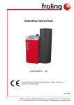
Operating Instructions
TX
English version of operating instructions for operators.
Read and follow the instructions and safety instructions!
Subject to technical change.
Fröling Heizkessel- und Behälterbau Ges.m.b.H
Industriestraße 12
A-4710 Grieskirchen
Fax +43 (0) 7248 606-600
[email protected]
www.froeling.com
Tel +43 (0) 7248 606-0
I
Introduction
Dear customer,
Congratulations on choosing a quality product from FRÖLING.
The FRÖLING TX wood chip boiler features a state-of-the-art design that
conforms to all currently applicable standards and testing guidelines.
Please read and observe the operating instructions and always keep
them close to the boiler for reference. They contain safety information
and all the operation and maintenance specifications needed to operate
the boiler safely, properly and economically.
The constant further development of our products means that the
pictures and content may differ slightly. If you discover any errors,
please let us know. Subject to technical change.
Guarantee conditions
Our sale and delivery conditions generally apply. These conditions have
been made available to customers, and customers have been made
aware of them at the time of order completion.
You can also find the guarantee conditions on the enclosed guarantee
certificate.
Address of manufacturer
FRÖLING
Heizkessel- und Behälterbau GesmbH
Industriestraße 12
A-4710 Grieskirchen
AUSTRIA
TEL +43 (0)7248 606 0
FAX +43 (0)7248 606 600
E-MAIL [email protected]
WEBSITE www.froeling.com
Page 2
B 067 00 09
v
Contents
1 Product Overview
C
5
1.1
5
2 Safety
8
2.1 Safety Information
8
2.2 Permitted uses
9
2.2.1 Permitted fuels ...............................................................................................9
Wood chips....................................................................................................9
Pellets ..........................................................................................................9
Changing the fuel ......................................................................................... 10
2.2.2 Non-permitted fuels....................................................................................... 10
2.3 Qualification of operating staff
10
2.4 Protective equipment for operating staff
11
2.5 Design Information
11
2.5.1 Official approval and obligation to report .......................................................... 11
2.5.2 Requirements for heating water ...................................................................... 11
2.5.3 Ventilation of boiler room ............................................................................... 12
2.5.4 Heating System Installation/ Standards ............................................................ 12
Storage tank................................................................................................ 12
Return lift.................................................................................................... 12
2.6 Safety devices
13
2.6.1 Devices for preventing the boiler from overheating ............................................ 14
Thermal discharge safety device ..................................................................... 14
Safety Temperature Limiter STL ..................................................................... 14
Safety valve (provided by the customer).......................................................... 14
2.7 Safety information for installation room
14
2.8 Residual risks
15
2.9 Emergency procedure
16
2.9.1 System overheating....................................................................................... 16
2.9.2 Smell of flue gas ........................................................................................... 16
3 Operating the system
3.1 Assembly and initial startup
17
17
3.2 Filling/ refilling the store with fuel
17
3.2.1 Loading wood chips in a partially emptied store ................................................. 17
3.2.2 Loading wood chips in an empty store .............................................................. 18
3.2.3 Blowing in pellets for a store with pellet screw................................................... 18
3.2.4 Blowing in pellets for a partially emptied store with stirrer................................... 19
3.2.5 Blowing in pellets for an empty store with stirrer ............................................... 19
3.3 Heating the boiler
21
3.3.1 Switching on the system ................................................................................ 21
3.3.2 Switching on the boiler .................................................................................. 21
3.3.3 Controlling the boiler ..................................................................................... 21
3.3.4 Switching off the boiler .................................................................................. 21
3.3.5 Switching off the System................................................................................ 21
4 Boiler maintenance
Fröling Heizkessel- und Behälterbau Ges.m.b.H Industriestraße 12 A-4710 Grieskirchen
Fax +43 (0) 7248 606-600
[email protected]
www.froeling.com
Tel +43 (0) 7248 606-0
22
Page 3
B 067 00 09
C
4.1 General information on maintenance
Contents
22
4.2 Inspection and cleaning
23
4.2.1 Inspection.................................................................................................... 23
Checking the thermal discharge safety device .................................................. 23
Check safety valve ....................................................................................... 23
Check the system pressure............................................................................ 23
Check the geared motors .............................................................................. 23
4.2.2 Cleaning ...................................................................................................... 24
Empty the ash container retort....................................................................... 24
Empty the heat exchanger ash container ......................................................... 25
4.2.3 Monthly inspection ........................................................................................ 26
Activate service mode................................................................................... 26
Clean the combustion chamber and combustion space....................................... 26
4.2.4 Annual inspection.......................................................................................... 28
Clean the heat-exchanger ............................................................................. 28
Clean the area below the step grate................................................................ 28
Clean the flue gas recirculation (FGR) (optional) ............................................... 29
Clean the induced draught fan ....................................................................... 30
Clean the combustion air blower fan ............................................................... 30
Check the under-pressure controller ............................................................... 30
Check the combustion chamber overpressure sensor ......................................... 31
Check door seals .......................................................................................... 31
Check the draught controller flap and explosion flap.......................................... 31
4.3 Instructions for measuring emissions
32
4.3.1 Measurement at rated load............................................................................. 32
Activate chimney-sweep mode ....................................................................... 32
4.3.2 Measurement at partial load (if necessary) ....................................................... 32
4.4 Maintenance agreement / Customer service
33
4.5 Replacement parts
33
5 Troubleshooting
34
5.1 General faults in power supply
34
5.1.1 System procedure following power failure......................................................... 34
5.2 Excessive temperature
34
5.3 Faults with fault message
35
5.3.1 Procedure for fault messages.......................................................................... 35
5.3.2 Acknowledging a fault message....................................................................... 35
Page 4
B 067 00 09
v
General
1
Product Overview
1 General
1.1 Product Overview
4.4
4
4.2
4.3
3
4.1
5
2
1
6
Pos.
7
Description
1
Wood chip boiler - Fröling TX
2
Switch cabinet with integrated Lambdatronic H 3200 controller
3
Main switch: switch the power supply on and off for the entire system
4
Control panel of the Lambdatronic H 3200 controller
4.1
Status LED (operating status):
4.2
Large graphical display to show operating statuses and parameters
4.3
Navigation keys to move around in the menus and to change the parameter values
4.4
Function keys for calling up individual boiler functions or modes directly
Symb.
- slow green flashing light: boiler activated
- fast green flashing light: boiler deactivated
- red flashing light: Fault
5
Insulated door
6
Automatic ash removal ashcan
7
Ash removal unit or second ash box with automatic heat exchanger ash removal
Fröling Heizkessel- und Behälterbau Ges.m.b.H Industriestraße 12 A-4710 Grieskirchen
Fax +43 (0) 7248 606-600
[email protected]
www.froeling.com
Tel +43 (0) 7248 606-0
Page 5
B 067 00 09
General
1
Product Overview
9
11
12
11
5
10
8
13
15
9
14
Pos.
Description
Symb.
8
Fuel transport unit with top gravity shaft, burn back flap or rotary valve as a burn back protection
system and stoker screw for fuel transport
9
Automatic tipping grate
10
Combustion chamber door
11
Heat exchanger door
12
Efficiency Optimisation System (WOS) with turbulators
13
Boiler outfeed connection
14
Boiler return connection
15
Thermal discharge safety device connection
Page 6
B 067 00 09
v
General
1
Product Overview
19
16
20
18
21
17
22
23
Pos.
Description
16
Automatic drive for heat exchanger cleaning
17
Induced draught fan
18
Flue gas recirculation (optional)
19
Secondary air control with actuator drive
20
Primary air control with actuator drive
21
Automatic ignition
22
Flue gas recirculation for step grate
23
Flue gas recirculation for tipping grate
Fröling Heizkessel- und Behälterbau Ges.m.b.H Industriestraße 12 A-4710 Grieskirchen
Fax +43 (0) 7248 606-600
[email protected]
www.froeling.com
Tel +43 (0) 7248 606-0
Symb.
Page 7
B 067 00 09
Safety
2
Safety Information
2 Safety
2.1 Safety Information
DANGER
Non-permitted use!
Incorrect use of the boiler can cause severe injuries and damage!
The instructions and information provided in the instructions
should be observed!
Details on procedure for operation, maintenance and cleaning, as
well as troubleshooting for the boiler are included in the
individual instructions. Any further work should be carried out by
authorised heating engineers or by Fröling customer services.
WARNING
External influences!
Negative external influences, such as insufficient combustion air or a
fuel that is not permitted can cause serious faults in combustion (e.g.
spontaneous combustion of carbonisation gases or flash fires) which
can in turn cause serious accidents!
Instructions and information for versions and minimum values, as
well as standards and guidelines for heating components in the
instructions must be observed!
WARNING
Severe injuries and damage can be caused by an inadequate flue gas
system!
Problems with the flue system, such as poor cleaning of the flue pipe
or insufficient chimney draught can cause serious faults in
combustion (such as spontaneous combustion of carbonisation gases
or flash fires)!
You can only be guaranteed of optimum performance from the boiler if the
flue gas system is running smoothly!
Page 8
B 067 00 09
v
Safety
2
Permitted uses
2.2 Permitted uses
The boiler should only be operated when it is in full working order. It
should be operated in accordance with the instructions, observing safety
precautions, and you should ensure you are aware of the potential
hazards. Ensure that any faults, which might impair safety, are rectified
immediately.
The TX series wood chip boiler is intended exclusively for
heating central heating water. Use only the fuels specified
under 2.2.1.
The manufacturer or supplier is not liable for any damages
resulting from non-permitted uses.
2.2.1 Permitted fuels
Wood chips
Designation as per
Description as per
ÖNORM M 7133
ÖNORM
M 7133
ÖNORM/DIN
CEN/TS 14961
Water
content
W20
M20
Air dried
W30
M30
Suitable for storage
Size
G30
P16
Fine wood chips
G50
P45
Medium wood chips
Applicable standards:
Austria:
Germany:
ÖNORM M 7133 or ÖNORM CEN/TS 14961
Wood chips in accordance with §3 (1) point 4 of the 1st
BImSchV in the applicable version.
Specifications as per DIN CEN/TS 14961 and/or
ÖNORM M 7133
§
Pellets
Wood pellets made from natural wood with a diameter of 6 - 10 mm
Applicable standards:
Austria:
Germany:
ÖNORM M 7135 - HP 1 and/or DINplus certification
program
DIN 51731 - HP 5, DINplus certification program and/or
ÖNORM M 7135 - HP 1
§
Generally applicable:
Before refilling the store, check for pellet dust and clean if necessary.
Fröling Heizkessel- und Behälterbau Ges.m.b.H Industriestraße 12 A-4710 Grieskirchen
Fax +43 (0) 7248 606-600
[email protected]
www.froeling.com
Tel +43 (0) 7248 606-0
Page 9
B 067 00 09
Safety
2
Qualification of operating staff
Changing the fuel
CAUTION
Incorrectly set fuel parameters:
Incorrect parameter settings have a significant effect on the
functioning of the boiler, and as a result this will void the guarantee.
If the fuel is changed (e.g. from wood chips to pellets), the system must be
reset by Fröling customer services.
2.2.2 Non-permitted fuels
CAUTION
Use of non-permitted fuels:
Burning non-permitted fuels leads to a build-up of aggressive
sedimentation and condensation, which can lead to damage to the
boiler and also voids the warranty!
All fuels not defined under 2.1.1 are considered non-permitted. Due to
various air-quality protection regulations, non-permitted fuels include:
• Chipboard waste, treated wood-wastes, pure grinding dust,
• Refuse, large quantities of paper, cardboard packaging, ...
• Coal (brown coal, anthracite coal, briquettes...)
2.3 Qualification of operating staff
Only trained operators are permitted to operate the boiler. The operator
must also have read and understood the instructions in the
documentation.
CAUTION
If unauthorised persons enter the boiler room:
Risk of injury and damage to equipment!
It is the responsibility of the operator to ensure that unauthorised persons,
especially children, are kept away from the boiler.
Page 10
B 067 00 09
v
Safety
2
Protective equipment for operating staff
2.4 Protective equipment for operating staff
You must ensure that staff have the protective equipment specified by
accident prevention regulations.
y During operation, inspection and cleaning of the boiler:
- Sturdy shoes
- protective gloves
2.5 Design Information
It is forbidden to carry out modifications to the boiler or to change or
deactivate safety equipment.
Always comply with all fire, building, and electrical regulations when
installing or operating the boiler system, and follow the operating
instructions and mandatory regulations that apply in the country in
which the boiler is operated.
2.5.1 Official approval and obligation to report
NOTICE
Each heating system must be officially authorised.
The appropriate supervisory authority (inspection agency) must always be
informed when a heating system is installed or modified, and authorisation
must be obtained from the building authorities.
Austria:
Report to the construction authorities of the community or
magistrate
Germany:
Report new installations to an approved chimney sweeper
and to the building authorities.
Other countries: Observe local regulations for authorisation
2.5.2 Requirements for heating water
The requirements for heating water are based on the following
standards:
Applicable standards:
Austria:
Germany:
Switzerland:
ÖNORM H 5195-1
VDI 2035
SWKI 97-1
§
If the system is topped up or refilled:
Prepare (soften) the water to prevent boiler scaling.
Fröling Heizkessel- und Behälterbau Ges.m.b.H Industriestraße 12 A-4710 Grieskirchen
Fax +43 (0) 7248 606-600
[email protected]
www.froeling.com
Tel +43 (0) 7248 606-0
Page 11
B 067 00 09
Safety
2
Design Information
2.5.3 Ventilation of boiler room
The openings for the supply air and the exhaust air should be arranged
as close to opposite each other as possible to achieve a good thermal
draught effect.
Draw in the supply air directly from outside. Expel the exhaust air
directly outside.
Provided they are not contradicted by the relevant building regulations
room where the boiler is to be installed, the following standards apply:
§
Applicable standards:
- TRVB H 118
- ÖNORM H 5170
Provide a supply air cross-section of 2 cm2 per kW of boiler rated output,
as per ÖNORM H 5170, but a total cross-section of at least 200 cm2
2.5.4 Heating System Installation/ Standards
The following standards govern the installation of heating systems:
Applicable standards:
ÖNORM / DIN EN 12828 Heating Systems in Buildings
§
Storage tank
NOTICE
A storage tank with the proper dimensions will guarantee the best boiler
operating values during the entire heating period.
Please contact your installer or Fröling directly for the right measurements for
the storage tank.
Return lift
If the hot water return is below the minimum return temperature, some
of the hot water outfeed will be mixed in.
CAUTION
Risk of dropping below dew point/condensation formation if operated
without return lift.
Condensation water forms an aggressive condensate when combined
with combustion residue, leading to damage to the boiler.
Regulations stipulate the use of a return lift.
Page 12
B 067 00 09
v
Safety
2
Safety devices
2.6 Safety devices
1
3
2
1
Automatic operation button
If the boiler overheats:
Press and hold this button for 5 seconds
Automatic operation is switched off and the controller
follows the boiler shutdown procedure
The pumps continue to run!
Never use the main switch!
2
Safety temperature limiter (back
of boiler)
3
Main switch
For shutting down the entire system:
Only switch off the main switch when the boiler has cooled
down and the controller is switched off (“Boiler off” status).
Turn the main switch to the “O” position
The power to all components is switched off.
Water sprinkler system
In case of burn back, the valve of the water sprinkler system
opens and water goes into the gravity shaft as well as the duct
of the feed screw.
This need only be connected when specified by the
authorities.
Not
shown
Page 14, Devices for preventing the boiler from overheating
Fröling Heizkessel- und Behälterbau Ges.m.b.H Industriestraße 12 A-4710 Grieskirchen
Fax +43 (0) 7248 606-600
[email protected]
www.froeling.com
Tel +43 (0) 7248 606-0
Page 13
B 067 00 09
Safety
2
Safety information for installation room
2.6.1 Devices for preventing the boiler from overheating
Thermal discharge safety device
At around 100 °C a valve opens and sends cold water to the safety
heat-exchanger to decrease the temperature.
Safety Temperature Limiter STL
2
Stops combustion at a max. boiler temperature of 105 °C. The pumps
continue to run.
Once the temperature has fallen below the unlocking point (approx.
95 °C), the safety temperature limiter (2) can be unlocked
mechanically.
Safety valve (provided by the customer)
Protection against over-heating/ excessive pressure:
When the boiler pressure reaches a maximum of 3 bar, the safety valve
opens and the heating water is released in the form of steam.
2.7 Safety information for installation room
• Danger of fire due to flammable materials. No flammable materials
should be stored near the boiler.
• Damage due to impurities in combustion air. Do not use any
solvents or cleaning agents containing chlorine in the room where
the boiler is installed.
• Keep the air suction opening of the boiler free of dust.
• The room where the boiler is installed must be frost-proof.
Page 14
B 067 00 09
v
Safety
2
Residual risks
2.8 Residual risks
WARNING
Touching hot surfaces!
Hot parts and the flue pipe can cause serious burns!
Always wear protective gloves when working on the boiler.
Only operate the boiler using the handles provided for this
purpose
Insulate the flue gas pipes and avoid touching them during
operation
Before carrying out maintenance work on/in the boiler:
Press and hold this button for 5 seconds
The controller follows the shutdown procedure and starts
with the cleaning cycle
After the cleaning cycle the boiler goes to the operating
status, “Cleaning possible”
WARNING
Opening the combustion chamber door during operation!
This may cause injury, damage and smoke!
It is forbidden to open the doors behind the insulating door
during operation!
WARNING
Use of non-permitted fuel!
Non-standard fuels can cause serious faults in combustion (e.g.
spontaneous combustion of carbonisation gases / flash fires) which
can lead to serious accidents!
Only use fuels specified in the chapter on “Permitted Uses” in
these operating instructions.
Fröling Heizkessel- und Behälterbau Ges.m.b.H Industriestraße 12 A-4710 Grieskirchen
Fax +43 (0) 7248 606-600
[email protected]
www.froeling.com
Tel +43 (0) 7248 606-0
Page 15
B 067 00 09
Safety
2
Emergency procedure
2.9 Emergency procedure
2.9.1 System overheating
If the system overheats in spite of the safety devices, proceed as
follows:
Keep all the doors on the boiler closed.
Turn off the boiler by pressing the
button for 5 seconds
Under no circumstances use the main switch!
Open all mixer taps and switch on all pumps.
Fröling heating circuit control takes over this function in
automatic operation.
When using a third party controller, carry out the relevant
measures to activate the mixer and pumps manually.
Exit the boiler room and close the door
Open any available radiator thermostat valves
If the temperature does not drop, inform the installer or Fröling
customer services:
2.9.2
Smell of flue gas
DANGER
Smell of flue gas!
Flue gases can cause fatal poisoning!
Keep all the doors on the boiler closed.
Turn off the boiler by pressing the
button for 5 seconds
Under no circumstances use the main switch!
Ventilate the installation room
Close the door of the installation room or boiler room and
doors to living areas
Page 16
B 067 00 09
v
Operating the system
3
Assembly and initial startup
3 Operating the system
3.1 Assembly and initial startup
Assembly, installation and initial startup of the boiler must only be
carried out by qualified staff, and these procedures are described in the
accompanying assembly instructions.
See TX assembly instructions
NOTICE
Optimum efficiency and efficient, low-emission operation can
only be guaranteed if the system is set up by trained
professionals and observing the standard factory settings.
Take the following precautions:
Initial start-up should be carried out with an authorised installer or with
Fröling customer services.
3.2 Filling/ refilling the store with fuel
When you fill the store you should always ensure that you are using the
right fuel:
Page 9, 2.2.1 Permitted fuels
Caution:
Depending on the fuel and the fill level, different procedures must be
followed for filling the fuel store.
3.2.1 Loading wood chips in a partially emptied store
If there is still sufficient fuel in the store (the head of the stirrer is
completely covered with fuel), the store can be filled:
Load the fuel at the filling opening
Fröling Heizkessel- und Behälterbau Ges.m.b.H Industriestraße 12 A-4710 Grieskirchen
Fax +43 (0) 7248 606-600
[email protected]
www.froeling.com
Tel +43 (0) 7248 606-0
Page 17
B 067 00 09
Operating the system
3
Filling/ refilling the store with fuel
3.2.2 Loading wood chips in an empty store
CAUTION! If the head of the stirrer is already free of material
and the arms / spring blades are extended, then the feeder
unit must be active during the filling process.
Press and hold this button for 5 seconds
“Extra heating” mode is activated
Load a small quantity of wood chips and wait at least half an hour
(preferably an hour) until the arms / spring blades are touching the
head of the stirrer
Only then should you load the remaining material
3.2.3 Blowing in pellets for a store with pellet screw
For systems with a pellet screw, the boiler must be in “OFF” status when
the store is filled. The under-pressure from the blowing could bring
smoke back into the store.
Switch off the boiler by pressing the
button for 5 seconds and
allow it to cool down for at least two hours.
Close all openings to the store to seal out dust
Blow the fuel into the store
Page 18
B 067 00 09
v
Operating the system
3
Filling/ refilling the store with fuel
3.2.4 Blowing in pellets for a partially emptied store with stirrer
If there is still sufficient fuel in the store (the head of the stirrer is
completely covered with fuel), the store can be filled:
Switch off the boiler by pressing the
button for 5 seconds and
allow it to cool down for at least two hours.
Close all openings to the store to seal out dust
Blow the fuel into the store
3.2.5 Blowing in pellets for an empty store with stirrer
CAUTION! If the head of the stirrer is already free of material
and the arms / spring blades are extended, then the feeder
unit must be active during the filling process, however the
boiler must be in “OFF” status.
Turn off the boiler by pressing the
button for 5 seconds and
allow it to cool down for at least two hours
Close all openings to the store to seal out dust
Fröling Heizkessel- und Behälterbau Ges.m.b.H Industriestraße 12 A-4710 Grieskirchen
Fax +43 (0) 7248 606-600
[email protected]
www.froeling.com
Tel +43 (0) 7248 606-0
Page 19
B 067 00 09
Operating the system
3
Filling/ refilling the store with fuel
repeatedly
Call up the “Manual operation” menu
Activate the following units in the order shown:
- Ash screw
ON
- Grate tip drive
ON
- Stoker
FORWARD
- BBF manual
ON
(or Rotary valve ON)
- Oufeeder - manual
FORWARD
Blow the fuel into the store
After about 5 minutes deactivate the parameter, “Outfeeder manual”, and the parameter “BBF manual” or “Rotary valve”
Wait until the stoker is completely emptied, and only then deactivate
the parameter, “Stoker”
If there is a fuel residue in the stoker, there is a danger of a flash
fire the next time the boiler is started, due to a excessive infeed
quantity.
Wait until all the pellets in the retort have been transported to the
ash bucket, and only then deactivate the parameter “Ash screw” and
the parameter “grate tip drive”
Remove all the pellets remaining on the grate from the combustion
chamber
If there is fuel residue in the boiler, the chamber can be damaged
the next time the boiler is started.
Empty the ash bucket after the end of the procedure
If there is fuel residue in the ash bucket, there is a danger of fire.
Page 20
B 067 00 09
v
Operating the system
3
Heating the boiler
3.3 Heating the boiler
3.3.1 Switching on the system
Turn the main switch on the side of the switch cabinet to the “ON”
position
After the system check by the controller, the system is ready for
operation
“Boiler Off” is shown on the display
3.3.2 Switching on the boiler
Press this button
Automatic mode is activated
The heating system is controlled via the controller according to
the selected mode.
3.3.3 Controlling the boiler
See the operating instructions for the Lambdatronic H 3200
3.3.4 Switching off the boiler
Press and hold this button for 5 seconds
The boiler follows the shut-down program and switches to “Boiler
OFF” status.
The combustion unit is switched off, the chamber discharge unit
and the active hydraulic system are active
3.3.5 Switching off the System
CAUTION! Only when the boiler is cold, in “Boiler Off” status!
Switch off the main switch on the controller
The controller is switched off
The components powered via the switch cabinet are powered
down
The expansion switch cabinet, which has its own power supply, is
still live!
Fröling Heizkessel- und Behälterbau Ges.m.b.H Industriestraße 12 A-4710 Grieskirchen
Fax +43 (0) 7248 606-600
[email protected]
www.froeling.com
Tel +43 (0) 7248 606-0
Page 21
B 067 00 09
Boiler maintenance
4
General information on maintenance
4 Boiler maintenance
4.1 General information on maintenance
DANGER
Working on electrical components
Risk of serious injuries from electric shocks
Work on electrical components should only be carried out by
authorised technicians
WARNING
Servicing when the boiler is switched on or hot:
Serious injuries from automatic startup of the boiler and serious
burns on hot parts and on the flue gas pipe are possible!
Only carry out work on the boiler when the main switch is
turned off
Always wear protective gloves when working on the boiler.
Only operate the boiler using the handles provided for this
purpose
Before maintenance work:
Turn off the boiler with the
key and allow it to cool down
When the boiler has cooled down, switch it off with the main
switch and secure so that it cannot be switched on again
WARNING
Non-permitted cleaning and maintenance!
Incorrect or insufficient cleaning and maintenance of the boiler can
cause serious faults in combustion (e.g. spontaneous combustion of
carbonisation gases / flash fires) and this can lead to serious
accidents and damage!
Only clean the boiler when it is in “Boiler Off” operating status
and in accordance with the instructions. Follow the boiler
operating instructions.
Page 22
B 067 00 09
v
Boiler maintenance
4
Inspection and cleaning
4.2 Inspection and cleaning
Regular cleaning of the boiler extends its life and is a basic
requirement for smooth running based on output. So clean the
boiler regularly!
Recommended: When cleaning, use an ash vacuum.
4.2.1 Inspection
Checking the thermal discharge safety device
Check the seal of the discharge valve at regular intervals
The discharge pipe must not drip
Exception: boiler temperature > 95 °C
If water is dripping from the discharge pipe:
Clean the discharge safety device or have the installer replace it if
necessary
Check safety valve
Check the safety valve as per the manufacturer’s instructions.
See the operating instructions of the safety valve
Check the system pressure
Read off the system pressure on the pressure gauge
The value must be above the pre-stressed pressure of the
expansion tank by 20%
Expansion tank operating instructions
If the system pressure decreases:
Top up the water
If this occurs frequently, the seal of the heating system is faulty!
Inform your installer!
In case of large pressure fluctuations:
Have the expansion tank checked
Check the geared motors
Carry out a visual inspection of the seal on the geared motors of the
stoker screw and ash screw
There must not be a large quantity of lubricant coming out.
If a few drops of lubricant are coming out, this can be normal. If a lot
of lubricant is being lost, inform your installer or Fröling customer
services.
Fröling Heizkessel- und Behälterbau Ges.m.b.H Industriestraße 12 A-4710 Grieskirchen
Fax +43 (0) 7248 606-600
[email protected]
www.froeling.com
Tel +43 (0) 7248 606-0
Page 23
B 067 00 09
Boiler maintenance
4
Inspection and cleaning
4.2.2 Cleaning
Notice -> Main switch OFF
Only check the ash level when “Boiler OFF”
Empty the ash container retort
The ash containers must be emptied at the correct intervals according to
energy requirements and fuel quality.
Remove the ash container cover and check the level
If the ash container is full, unscrew the wing nuts on the discharge
flange
When removing the ash container, insert the transport handle and
secure with a split pin
Separate the ash container and take it to the ash disposal point
Page 24
B 067 00 09
v
Boiler maintenance
4
Inspection and cleaning
Empty the heat exchanger ash container
For heat exchanger with ashcan:
Remove the star-shaped screws of the ashcan
Take out the ashcan and remove the ash
For heat exchanger with ash screws:
Remove the ash container cover and check the level
If the ash container is full, unscrew the wing nuts on the flange
Separate the ash container and take it to the ash disposal point
Fröling Heizkessel- und Behälterbau Ges.m.b.H Industriestraße 12 A-4710 Grieskirchen
Fax +43 (0) 7248 606-600
[email protected]
www.froeling.com
Tel +43 (0) 7248 606-0
Page 25
B 067 00 09
Boiler maintenance
4
Inspection and cleaning
4.2.3 Monthly inspection
Activate service mode
For cleaning tasks in the boiler activate service mode:
Press and hold this button for 5 seconds
The controller follows the shutdown procedure and starts with the
cleaning cycle
After the cleaning cycle the boiler goes to the operating status,
“Cleaning possible”
The tipping grate remains in open position
Switch off the main switch
Clean the combustion chamber and combustion space
Open the insulated doors and heat exchanger door
Remove a lot of ash from the combustion space with a shovel
Clean the combustion chamber sensor with a soft brush
Clean the side walls of the combustion space with the furnace tool
Bring the remaining ash down into the combustion chamber below
with the furnace tool
Page 26
B 067 00 09
v
Boiler maintenance
4
Inspection and cleaning
Close the heat exchanger door and open the combustion chamber
door
Remove a lot of ash with a shovel
Clean the step grate and sloping plates with the furnace tool
Clean the side walls of the combustion chamber with the furnace tool
Clean the primary air openings in the step grate and sloping plates
with a suitable tool (screwdriver or similar)
After cleaning the combustion space and the combustion chamber:
Close the boiler doors and insulated doors
Switch on the main switch
The tipping grate closes and the controller switches to “Boiler
Off” mode.
Switch off the main switch again and open the doors
Check the cleanliness of the tipping grate once more in closed
position and clean the air openings with a suitable tool
(screwdriver or similar)
Fröling Heizkessel- und Behälterbau Ges.m.b.H Industriestraße 12 A-4710 Grieskirchen
Fax +43 (0) 7248 606-600
[email protected]
www.froeling.com
Tel +43 (0) 7248 606-0
Page 27
B 067 00 09
Boiler maintenance
4
Inspection and cleaning
4.2.4 Annual inspection
Carry out annually, however at least after 2500 service hours!
For the annual inspection:
Switch off the main switch when the boiler has cooled down
Clean the heat-exchanger
Remove the insulated cover and open the cleaning cover
Remove all dirt and deposits for the flue gas chamber.
Clean the area below the step grate
Remove the blanking plate and the thermal insulation
Remove the inspection cover
Clean away the ash below the step grate with the furnace tool or an
ash vacuum
Clean the side passage to the flue gas recirculation (optional)
Page 28
B 067 00 09
v
Boiler maintenance
4
Inspection and cleaning
Clean the flue gas recirculation (FGR) (optional)
Remove the pipe insulation from the
inspection cover.
Remove the inspection cover and
clean the pipes of the flue gas
recirculation unit with a brush
After cleaning the pipes:
Remove the inspection cover of the flue gas recirculation box
Clean the interior with an ash vacuum
Remove the inspection cover of the
flue gas recirculation air box
Clean the interior with an ash vacuum
Fröling Heizkessel- und Behälterbau Ges.m.b.H Industriestraße 12 A-4710 Grieskirchen
Fax +43 (0) 7248 606-600
[email protected]
www.froeling.com
Tel +43 (0) 7248 606-0
Page 29
B 067 00 09
Boiler maintenance
4
Inspection and cleaning
Clean the induced draught fan
Remove both cables from the induced draft fan
Mark the flange position and loosen the screws on the fan flange
Take out the induced draught fan and clean the blower wheel with a
brush.
Clean the interior of the induced draught fan housing with an ash
vacuum
Clean the combustion air blower fan
Clean any dust and deposits from
the protective grating
Dismantle the protective grating and
clean the fan with a soft brush where
necessary.
Check the under-pressure controller
Remove the silicon tube from the
differential pressure transducer.
Using compressed air, blow out the
hose in the direction of the
combustion chamber to remove any
deposits.
Connect the silicon hose at “Minus”.
Page 30
B 067 00 09
v
Boiler maintenance
4
Inspection and cleaning
Check the combustion chamber overpressure sensor
Loosen the retaining screw.
Pull the combustion chamber
overpressure sensor out of the
spacer pipe.
Clean the sensor with a fine cloth.
Check that the spacer pipe is free.
Insert the combustion chamber
overpressure sensor and fix gently
with fixing screws
Check door seals
Check that the ceramic fibre seal of the combustion chamber door,
the heat exchanger door and the heat exchanger cover is positioned
correctly on the frame
Check the imprint on the ceramic fibre seal.
If the imprint of the seal is broken:
The seal is no longer efficient.
Adjust the door fastenings or replace the glass fibre seal
After adjusting the combustion chamber door and the heat
exchanger door, you must check that the door contact switch is
working and if necessary it must be reset.
Check the draught controller flap and explosion flap
Check the draught controller flap and explosion flap for ease of
operation
If they cannot move smoothly, have them replaced immediately.
Fröling Heizkessel- und Behälterbau Ges.m.b.H Industriestraße 12 A-4710 Grieskirchen
Fax +43 (0) 7248 606-600
[email protected]
www.froeling.com
Tel +43 (0) 7248 606-0
Page 31
B 067 00 09
Boiler maintenance
4
Instructions for measuring emissions
4.3 Instructions for measuring emissions
4.3.1 Measurement at rated load
Ensure the highest possible heat consumption:
- Ensure that heating pumps are switched on
- Open mixer valves and radiator valves
- Set the boiler loading time to the current time
- Set the boiler temperature setpoint to 85°C
Chimney sweep mode takes over this function
Activate chimney-sweep mode
Press this button
The chimney sweeper program for boiler measurement is started.
The system is operated for 45 minutes at rated load. For this
purpose the maximum boiler temperature, the maximum heating
circuit flow temperature and the DHW tank loading are released.
When is it possible to measure:
• Flue gas temperature at approx. 140°C
• O2 content of the flue gas between 8 and 12% (corresponds to a
CO2 content between 13 and 19%)
• Boiler temperature above 65°C
4.3.2 Measurement at partial load (if necessary)
Ensure heat consumption:
- Ensure that heating pumps are switched on
- Open mixer valves and radiator valves
- Set the boiler loading time to the current time
Force partial load:
- After measuring at rated load, lower the boiler temperature
setpoint by 5°C
When is it possible to measure:
• Flue gas temperature at approx. 120°C
• O2 content of the flue gas between 10 and 14% (corresponds to a
CO2 content between 11 and 7%)
• Boiler temperature above 65°C
After measurement all adjusted parameters (e.g. DHW tank loading
times, ...) must be reset to their original value!
Page 32
B 067 00 09
v
Boiler maintenance
4
Maintenance agreement / Customer service
4.4 Maintenance agreement / Customer service
Long service life with a service agreement!
Regular maintenance and servicing by a heating specialist will ensure a
long, trouble-free service life for your heating system. It will ensure that
your system stays environmentally-friendly and operates efficiently and
cost-effectively.
For this reason, FRÖLING offers a service agreement, which optimises
operating safety. Please see the details in the accompanying guarantee
certificate.
Your Fröling customer service office is also glad to advise you.
4.5 Replacement parts
With Fröling original replacement parts in your boiler, you are using
parts that match perfectly. As the parts fit together so well, installation
times are shortened and lifespan is maintained.
NOTICE
Installing non-original parts voids the guarantee!
Only replace components or parts with original replacement parts
Fröling Heizkessel- und Behälterbau Ges.m.b.H Industriestraße 12 A-4710 Grieskirchen
Fax +43 (0) 7248 606-600
[email protected]
www.froeling.com
Tel +43 (0) 7248 606-0
Page 33
B 067 00 09
Troubleshooting
5
General faults in power supply
5 Troubleshooting
5.1 General faults in power supply
Error characteristics
Nothing is shown on the
display
No power to the controller
5.1.1
Cause of error
• General power failure
• FI circuit breaker or line
protection is switched off
• Main switch is turned off
• Faulty glass tube fuse in the
controls
Error correction
Switch on the FI circuit breaker or
line protection
Switch on the main switch
Switch off the main switch
Replace fuse – note current
(e.g. 10A)
Switch on the main switch
System procedure following power failure
When the power supply has been restored the boiler returns to the
previously specified mode and is controlled according to the specified
program.
5.2 Excessive temperature
2
The safety temperature limiter (STL) shuts down the boiler when it
reaches a temperature of max. 105°C. After the boiler has cooled down,
the safety temperature limiter must be manually unlocked:
Unscrew the cap on the safety temperature limiter (2)
Reset the safety temperature limiter by pressing with a screw-driver.
Replace the cap
Page 34
B 067 00 09
v
Troubleshooting
5
Faults with fault message
5.3 Faults with fault message
2
1
If a fault has occurred and has not yet been cleared:
Status LED (1) flashes red
A fault message is shown on the display (2)
An internal distinction is made between 2 types of message:
Warning
Boiler follows shutdown procedure
Error
Boiler shuts down immediately, heating circuit controller
and pumps remain active
5.3.1 Procedure for fault messages
The procedure in case of fault message, the causes for faults and
procedure for troubleshooting are described in the operating instructions
for the boiler controller:
See the operating instructions for the Lambdatronic H 3200
5.3.2 Acknowledging a fault message
Trace and remove the fault and then:
Press this button
Status LED flashes green
Fröling Heizkessel- und Behälterbau Ges.m.b.H Industriestraße 12 A-4710 Grieskirchen
Fax +43 (0) 7248 606-600
[email protected]
www.froeling.com
Tel +43 (0) 7248 606-0
Page 35
B 067 00 09