1
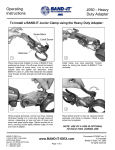
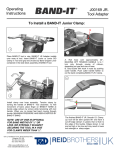
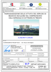
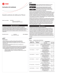
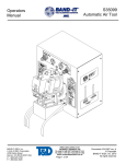
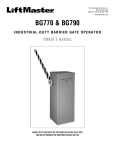
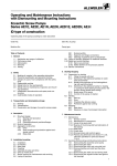
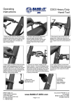
J05069
Heavy Duty Adapter
Operating
Instructions
Installing a Band-It Junior Clamp
Screw
Block
1
Cutoff
Screw
Setscrew
2
Place Heavy Duty Adapter on nose of BAND-IT Tool, positioned as shown. Cut-off screw should not extend beyond
bottom of screw block. Line up tool and adapter slots and
tighten two setscrews. Insert BAND-IT Junior or Junior SID
clamp tail into adapter nose through all slots and grip end with
band gripper lever.
Install clamp over hose assembly. Tension clamp by turning
handle of BAND-IT Tool clockwise.
3
4
Place ratchet wrench on hex nut. Operate wrench clockwise
until clamp is sheared. Clamp is now locked and completed.
When properly tensioned, roll tool over hose, backing off
tension handle ¼ to ½ turn only, through course of rollover,
(depending on type and size of hose) until shear hook grips
buckle edge. Tighten knurled nut by hand, securing buckle
tightly between edge of hook and nose of adapter.
5
The finished BAND-IT Junior SID clamp lip lock will be bent upward 90° and have a cut-off edge
(shown in green) that is flush to the edge of the buckle. Edges shown in red with hash marks are
too high or too low and may result in lower lock strength or sharp edges.
BAND-IT-IDEX, Inc.
www.BAND-IT-IDEX.com
A Unit of IDEX Corporation
© Copyright
4799 Dahlia Street
Denver, CO 80216-0307 USA
Document # P35387 rev. H
BAND-IT-IDEX, Inc. 2012
Page 1 of 2
All rights reserved
J05069
Heavy Duty Adapter
Repair Parts
& Assembly
14
7
* J93099 Exploded View
9
10
3
8
2
11
4
12
6
1
5
*NOTE: Replacement cutter
blade kit design may vary.
See Exploded View
J050 Heavy Duty Adapter, Repair Parts List
Notes:
To assist in removing threaded parts, apply heat to soften
locking compound.
Band-It
Part No.
Item #
When connecting item 9 (knob) or item 7 (nut) to item 8
(screw), clean threads (male and female) of foreign matter, then apply one drop of medium strength locking compound (Loctite 242 or equivalent) onto male thread and
connect parts together.
J00587
1
Shear Hook (Design may vary)
1
J00987
2
Pin, Grooved
1
3
Pin, Grooved
2
4
Body
1
5
Socket Head Screw
2
6
Screw Block
1
7
Hex Nut
1
8
Jr. Adapter Screw
1
9
Knob
1
10
Screw, Special
2
11
Backing Plate
1
12
Cutter Blade
1
13
Hex Key, 3/16” (not shown)
1
J11985
14
Ratchet Wrench
1
J01387
15
Hex Key, 3/16” (not shown)
1
Periodically check item 10 (screw) for tension. Loosened
screws may result in assembly breakage.
Operating Tip: Keep the bolts tight (8-14 ft-lbs.). A loose
bolt may cause cracking or premature wear of the cutter
blade and/or backing plate. This could result in improper
clamp tensioning, locking, and cutting.
Operating Tip: Keep the leading edges of the cutter blade
and backing plate free of metal shavings. Metal shavings
will result in clamp tail gouging during tensioning. Clean
and hone the leading edges by hand. Do not use
power tools. Honing should polish surfaces, not remove material.
J05187
J06787
J06887
Description
Qty.
J93099
Refer to website for warranty information: http://www.band-it-idex.com/warranty.html
BAND-IT-IDEX, Inc.
www.BAND-IT-IDEX.com
A Unit of IDEX Corporation
© Copyright
4799 Dahlia Street
Denver, CO 80216-0307 USA
Document # P35387 rev. H
BAND-IT-IDEX, Inc. 2012
Page 2 of 2
All rights reserved