1
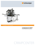
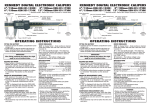
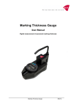
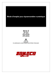
Schleuniger CHM
-1-
Operating Instructions
CHM
Crimp Height Measuring Device
Edition 1, 09/2006
© Schleuniger, 2006
Version 1, 09/2006
50940.000.580
Schleuniger CHM
-2-
Table of Contents
1. General Information
1.1 Explication of Symbols
1.2 Product Description
1.3 Technical Information
3
3
3
3
2. Operation Instructions
4
3. Dial Gage
3.1 Operation
5
4. Overview of the System
5
© Schleuniger, 2006
Version 1, 09/2006
Schleuniger CHM
-3-
1. General Information
1.1 Explication of Symbols
)
This symbol refers to tips and tricks of the Technical Service Center. It further
includes other information to be observed.
1.2 Product Description
The KMF CHM is designed for measuring the crimp height of wire as well as insulation crimps. The
measuring contacts of this device were developed especially for this purpose.
The contacts are provided with a spring which ensures a constant pressure during the measurement.
A constant measurement is thereby guaranteed – irrespective of the user.
1.3 Technical Information
Operating voltage
Dimensions
Weight
Interface
Real-time clock
© Schleuniger, 2006
5V DC 40 mA
155 mm (L) x 125 mm (W) x 235 mm (H)
Approx. 3,500 g
RS232
Mitutoyo 543-691B Digimatic, 0.001, mm
Version 1, 09/2006
Schleuniger CHM
-4-
2. Operating Instructions
It is to be ensured that the crimp height measurements are effected correctly. The crimp height
measuring device includes a flat contact blade on the one side and a precise contact on the other.
The precise contact serves the avoidance of faulty measurements in case of objects which are soiled
with burr. Normal callipers would also measure the burr entailing a falsification of the measuring
result.
Correct
crimp-height
Measured
Measured
crimp-height
crimp-height
Burr
The measuring object is to be positioned in a way that the side of the crimp which is rolled in is
diagonal to the blade contact and at right angles to the edge of the lower contact. Furthermore, the
object is to be placed horizontally on the edge. Tilted objects may falsify the measuring result.
The upper precise contact is to be positioned exactly in the middle of the crimp in order to measure
the highest point of the crimp. If the upper contact is not placed exactly in the middle of the crimp
area, the measuring result may be falsified.
Contact blade
Upper contact placed in the
middle of the crimp area
Crimp area
The side of the crimp which is
rolled in is placed flatly on the
lower contact Upper
Lower contact
)
The object must be at right angles to the edge of the lower contact and rest on
it horizontally. The upper contact point is to be positioned exactly in the
middle of the crimp.
© Schleuniger, 2006
Version 1, 09/2006
Schleuniger CHM
-5-
3. Dial Gage
3.1 Operation
•
Switch on the gauge by actuating the ON/OFF button.
•
By means of the +/- keys, you can switch between the normal mode in case of which the
display counts up and the reverse mode in case of which the display counts down (REV).
Make sure that the gage is always in the normal mode.
•
By pressing the ORIGIN key (longer than 1 second), the zero point is set at the current
position.
© Schleuniger, 2006
Version 1, 09/2006
Schleuniger CHM
-6-
4. Overview of the System
Real-time clock
Lever
Upper precise contact
Lower blade contact
© Schleuniger, 2006
Version 1, 09/2006