1
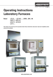
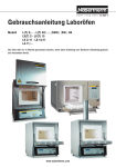
Operating Instructions Laboratory Furnaces Model L(T) 3/.. - L(T) 40/.. ; /SKM ; /SW ; HA LV(T) 3 - LV(T) 15 LE 2/11 - LE 14/11 LA 11/.. The furnace may only be put into operation when these instructions have been read and completely understood by the operator. www.nabertherm.com LE .. Laboratory furnace, economy series L ../3/.. Size ../HA Laboratory furnace with recirculating air blower in the back wall. ../SKM Furnace chamber of ceramic muffle ../SW Weighing furnace with bogie and balance These operating instructions must be read by every user and must be available at all times. Content Designated use............................................ 2 General description...................................... 2 Safety......................................................... 3 Installation and commissioning....................... 4 Operating notes........................................... 7 Maintenance and fault clearance..................... 8 Troubleshooting........................................... 9 Repair instructions..................................... 10 Disposal.................................................... 12 Circuit diagrams..........................................13 Wiring of the heating elements..................... 18 Declaration of Conformity............................ 19 Nominal temperatures L ../11/.. = 1100 °C L ../12/.. = 1200 °C L ../13/.. = 1300 °C Equipment • All models are equipped with a high-quality, multi-layer and energy-saving heat insulation • LV .. models have an air-preheating system and an air flow rate per minute which is at least six times the chamber volume at temperatures above 500 °C. • All models are equipped with a Controller which provides safety against most operating errors. The furnace chamber temperature is measured and regulated by a long-life thermocouple NiCr-Ni (Tmax < 1100 °C) or PtRh-Pt (Tmax > 1100 °C). Designated use • All laboratory furnaces are designed for commercial use in laboratories. • Furnaces of the LV-series are especially designed for ashing of laboratory samples. • A written agreement of Nabertherm is required if the furnace is to be used for other applications. • The installation instructions and safety regulations must be observed since otherwise the furnace is not regarded as being operated in accordance with the designated use and all claims against Nabertherm become void! Technical specifications Model General description Explanation of the model names: L .. Laboratory furnace with flap door LT .. Laboratory furnace with lifting door LV .. Laboratory ashing furnace with hinged door LVT .. Laboratory ashing furnace with lifting door Width* Depth* Height* Weight mm mm mm kg LE 2/11 275 380 330 10 LE 4/11 350 400 400 18 LE 6/11 510 400 320 18 LE 14/11 555 500 370 25 L(T)(V) 3/.. 380 370 420 20 L(T)(V) 5/.. 440 470 520 35 L(T)(V) 9/.. 480 550 570 45 L(T)(V) 15/.. 480 650 570 55 L(T) 24/.. 560 660 650 75 L(T) 40/.. 600 790 650 95 *Outer dimensions Model Width* Depth* Height* Weight mm mm mm kg L 9/11/SKM 480 L 9/11/SW 550 570 50 LA 11/.. 480 550 800 55 485 425 565 27 *Outer dimensions Furnace ratings: see the type plate on the lefthand furnace side Dimensions and weights: see table Protection class: 1 Enclosure rating of the furnace: IP 20 Thermal safety according to EN 605192-2, 1993: • without safety controller: Class 0, in case of error no protection for furnace or material. • with safety controller: Class 2, in case of error furnace and material are protected Ambient conditions Temperature: 5 - 40 °C Humidity: max. 95 %, non-condensing Safety CAUTION! Hot surface Risk of burns • Check the furnace for perfect condition before starting operation (with LE-models check especially the radiant heaters). Stop operation of the furnace immediately in case of a failure. If the furnace is operated in an imperfect condition there is danger to life and limb. • The furnace may not be used for heating food and drink for the purpose of consumption. • When operating the furnace considerable amounts of heat as well as harmful gases and vapours can be released depending on the type of material used. These must be led outside in an appropriate manner. Non-observance can result in a fire risk and danger to health. For more information see “Assembling an exhaust pipe”. • Operating the furnace with explosive gases or mixtures, or with explosive gases or mixtures created in the process is not permitted. Caution: Danger to life! If the furnace is provided with a protective gas connection only non-flammable and non-explosive protective gases are permitted. • Only use materials whose properties are known. • In case of unexpected procedures inside the furnace (e.g. strong smoke or odour development) switch the furnace off immediately and wait until it has cooled down by itself. Do not open the door beforehand – there is a risk of fire or explosion. • The furnace housing/lid and the door handle/ handle can get very hot during operation. If the furnace is opened at high temperatures (even when a great distance is kept) there is a risk of burns. Wear suitable protective clothing/safety goggles. • Do not bring any flammable material close to the furnace (keep a safety distance of 0.5 m to the sides and 1 m to the top). • Do not place any objects on the furnace as otherwise the carrying-off of heat is impeded, the furnace is damaged and there is a fire hazard. • Do not insert objects into the openings in the furnace casing, such as exhaust air holes or cooling slots of the switching system. There is a danger of electric shock. • The models L ../11/.. and L ../12/.. contain ceramic fibre material. In the Federal Republic of Germany actively handling this fibre (e.g. replacing the insulation) is subject to the regulations of the German ordinance concerning hazardous materials, Annex V No. 7 “Artificial mineral fibres” of June 12, 1998. In the other territories of the European Community ceramic fibres are classified by the Directive 98/69/EC of the Commission of December 5, 1997 as follows: CARC. Cat. 2; R 49; Xi R 38. Working on the fibre insulation must therefore be executed in such a way that the quantity of fibre dusts released is kept at a minimum. We recommend wearing a breathing mask (P2 or higher), protective gloves and a protective suit when working on the insulation or having work done by an expert. Installation site: • Place the furnace on a non-flammable support (stone, metal or similar). Keep a safety distance from flammable components of 0.5 m to the furnace sides and 1 m to the top. The minimum distance between the furnace sides and non-flammable materials can be reduced to 0.2m. • Provide sufficient room ventilation to carry off exhaust heat and gases which develop during the process. Non-observance can result in a fire risk and danger to health. Mounting the chimney: Depending on the application/order different chimneys are delivered (not included in the scope of supply with a protective gas connection). Installation and commissioning Transportation: • Wear protective gloves. • At least two persons (or even more, depending on the furnace size) are required for carrying/ transporting the furnace. • Grip under the furnace sides. • When using belts these must be placed laterally (crosswise). Angled chimney (not for LV-models) Removing the transport packaging: • Remove the transport packaging completely (also inside the furnace). • Please inform us immediately of any transport damage or incomplete delivery! • Note for furnace insulations with lightweight refractory bricks: The bricks used may have small holes or blowholes in some parts which are due to the manufacturing process. These holes are normal and a quality characteristic of the lightweight refractory brick. • Keep the packaging for any service case which might occur. • A chimney that diverts the gases and fumes escaping from the exhaust air nozzle (back wall) and lets them escape at the top. Cross section: 40 x 30 mm • Put the chimney on the exhaust air nozzle at the furnace back wall and fasten with the two screws provided. • It must be ensured that the catalyst is in operation from the program start up to about 600 °C. No statement can be made about the residual substances that are emitted into the environment. They depend to a high degree on the individually employed materials/embedded masses and their composition. Cross section: 120 x 120mm • Fasten the U-shaped holder with the two screws provided to the furnace back wall, put the piece of tube on the exhaust air nozzle of the furnace and screw down the chimney (with catalyst) on the holder. Plug the connector in the receptacle on the back of the switchgear (option) or in an external receptacle. Chimney with fan (not for LV-models) • Supports ventilation of the gases and fumes from the furnace chamber. Cross section: 85 x 60 mm • Put the chimney on the exhaust air nozzle at the furnace back wall and fasten with the two screws provided. Plug the connector in the receptacle on the back of the switchgear or in an external receptacle. With LV-furnaces: • These models are delivered with a special exhaust gas tube. • Fasten the angular tube with the screws provided to the inside housing of the furnace, then fasten the round tube with the screws provided to the outside housing. • When the furnace is operated without this tube, this will result in a reduced air flow rate which is insufficient for the incineration process. • Please note: Installation of a catalyst or chimney with fan is not possible with these models. Chimney with fan and catalyst (not for LVmodels) • Heats up the gases and fumes of the furnace chamber to about 600 °C and feeds them through the catalyst honeycomb. During this process the organic constituents are almost completely burnt catalytically, i.e. are decomposed in carbon dioxide and water vapour. This eliminates most unpleasant smells (e.g. during waste-wax casting). • Attention! Inorganic substances such as heavy metals, halogen, silicone and fine particulates (even small quantities) can destroy the catalyst! • Put the ceramic plate with the guide on the tube and align exactly. The tube must be placed freely on the balance and must not touch the furnace insulation so that the measuring result is not affected. • Connect balance with the mains plug. • The function of the balance is described in more detail in the separate instructions enclosed. • Separate instructions for MV-software (option) Assembling a ventilation pipe: Ventilation pipe Ø 80mm assembled at a constant rise about 50mm (bypass) Electrical connection: • Plug the mains plug in a corresponding receptacle which is protected sufficiently depending on the rated power of the furnace. If the furnace is ordered/delivered without plug, a qualified electrician must connect the furnace. • Please note: Using extension cables and/or junction boxes may lead to a reduced furnace output due to the voltage drop in the lines. The power is also reduced if the connection line to the junction box is very long, so that the furnace does not reach its nominal temperature. Please have the connection checked by an electrician. The voltage may not drop below the rated load by more than 10%. Ventilation chimney • In any case, we recommend to connect the furnace to an exhaust ductwork and to lead the arising gasses out. • A standard ventilation pipe of metal with NW80 - NW 120 can be used. It must be laid at a constant rise and fastened to the wall or ceiling. • Position the pipe in center above the chimney (NW 120 is not required for models with ventilation fan or catalyst). • Do not mount the ventilation pipe directly to the chimney as otherwise a bypass effect cannot be produced. The bypass effect is required to prevent a too high quantity of fresh air being sucked through the furnace. (Exception LV-furnaces: with these models the ventilation pipe NW80 can be put directly onto the chimney). • Caution: The exhaust gases can only be carried off if the room is ventilated by a corresponding fresh air opening. Mounting the balance (only with the ./SW model): • Insert the tube from below into the hole of the furnace floor. • Place the balance in the frame below the furnace. Lift the tube and set it on the bearing area of the balance. To secure the tube, push the supporting stamp in between tube and bearing area of the balance while lifting the tube. Entering temperatures and programs • Separate instructions for the Controller are enclosed (for the safety regulator as well if the regulator is provided as option). First heating up • To dry out the brick lining and to create an oxide protection layer on the resistance wire the furnace must initially be heated up. This may cause an unpleasant smell. Provide sufficient ventilation. • Heat the empty furnace up to 1050 °C in 6 hours (for LE furnaces: heat up to 1000 °C without ramp), maintain this temperature for one hour, then let the furnace cool down by its own. • The furnace is now ready to operate. Operating notes • Note for LE-models: Permanent temperatures above 1050 °C lead to a higher wear of the heating elements. General notes • The insulation consists of high-quality refractory material which is susceptible to shocks. Take care not to knock against the refractory material when charging the furnace to avoid damage. • In order to achieve an even temperature distribution the furnace should be charged in such a way that the products have a certain distance to each other and also to the side walls. Nabertherm offers shelves etc. so that the furnace chamber can be used in a better way. • If the furnace is charged with a high quantity of products the heating time may prolong considerably. • The furnace heating is interrupted when the door is opened and is switched on automatically after the door was closed (not with LEmodels). • The heating program must be interrupted when the furnace is charged to protect the operator and the furnace itself. In case of inobservance there is danger of an electrical shock. • Do not open the furnace when it is hot. If the furnace must be opened at high temperatures reduce this time to the minimum possible. Wear protective clothing and provide sufficient room ventilation. Regulating the fresh air supply • The volume of fresh air supplied can be set at the fresh air lever. The lever is located on the right-hand side of the door with models with hinged door and with models with lifting door at the bottom of the door. The position is explained by the symbols beside the lever. In position ● the fresh air opening is openend, in position ○ it is closed. • Note for use of a catalyst or exhaust air blower: Switch the fresh air lever in position ● as otherwise the exhaust gases cannot be removed from the furnace chamber. • Note for LV-models: These models are equipped with an independent fresh air system which cannot be controlled. The fresh air is led through holes in the back wall in to the upper heating plate where it is preheated and exits to the front above the furnace chamber. When the fresh air lever is in position ● not preheated fresh air is supplied. Switch the lever in position ○ to preheat the fresh air completely. • Switch the lever in position ○ in case of a protective gas connection/operation. Note in case of operation with reduced atmosphere/protective gas • Reducing atmosphere (deoxidation/exlusion of oxide) has a corrosive effect on the oxide protection layer of the resistance wire. Therefore, the next operation is to be carried out in normal atmosphere with the fresh air lever opened so that the oxide protection layer on the resistance wires can regenerate. • Make sure that the door is correctly closed. • Discolourations may occur on the stainless steel housing (especially when the hot furnace is opened); these, however, do not affect the function. Note for .../HA models The air-circulating motor is started when the program is started and is switched off automatically at program end and when the furnace chamber temperature has dropped below 80 °C. The furnace must not be switched off or disconnected from the mains above this temperature. Otherwise the air-circulating motor might be damaged. Maintenance and fault clearance Regularly clean the ventilation holes/pipes so that the ventilation cross-section remains unobstructed and the suction functions well. In the case of commercial use: Please observe the safety regulations applicable to your country. According to a regulation of the German employer‘s liability insurance association the furnace must be checked by a qualified electrician at specified intervals. Use the error search list (Troubleshooting), the repair instructions and the circuit diagram (see the following pages) to identify and eliminate errors. Cracks in the insulation: The insulation of the furnace consists of very high-quality refractory material. As a result of heat expansion, cracks appear in the insulation after a few heating cycles. However, these cracks have no influence on the function or quality of the furnace. Troubleshooting Error Cause Error elimination Controller does not switch on No voltage or Controller is defective • Check/replace the fuse(s) of the connection • Check/replace the fuse of the Controller (if installed) • Check plug connection Controller indicates error See Controller instructions No heating of the furnace chamber after the program was started or very slow heating or selected final temperature is not reached Mistake while entering the program Check heating program (see Controller instructions) Door-Safety switch interrupts Check whether the door or lid is closed: If yes, have switch path of the safety switch checked and if necessary re-adjusted by Nabertherm service. Fuse/s of the connection is/are defective Check fuse(s) of the connection, replace if necessary. Inform Nabertherm service if the new fuse blows as soon as it is screwed in. Heating element is defective Search for fractures, if no fractures are visible: • Close the cold furnace • Switch on the furnace for about 5 seconds (not longer) • Pull mains plug • Open the door By carefully touching the heating elements check the heat at various positions cold heating elements = heating circuit defective, for repair please see repair instructions No heating power as a result of undervoltage Have checked by Nabertherm service. Repair instructions Replacing the heating plates or heating coil (except LE-models) Only a qualified electrician may carry out work on the electrical system! This also applies to repair work which is described hereafter. Removal • Pull mains plug • Remove back wall cover • Loosen and remove terminals at the ends of the heating coil • Pull off wall ducts (at L 3/.. pull of silicone hoses first) • Pull out any fixing clamps from the lining (furnace chamber). • Take side ceramic support pipes (L 5/.. - L 15/..) out of the chamber • Remove the heating plates or the heating coil Ordering spare parts In writing, by phone or via the Internet: www.nabertherm.com State the following information from the type plate: • Furnace model • Production or serial number • Year of construction Insertion • Clean furnace chamber and wall ducts from residues. • If cleaning the wall ducts is not possible, insert new pipes. • Insert new heating plates or heating coil, push connection ends through the holes. • Put new fixing clamps* in the brick lining (do not use the old holes). • Place a small amount of fibre wool* around the connection ends from the outside and insert wall ducts. • Make the electrical connections with new terminals*: Hold terminal bottom with tongs, tighten the screw. • Cut off any excess twisted wire ends. If a line must be connected using a cable lug: Place cable lug onto the thread of the tightened screw and secure with hexagon nut. Hold screw so that it cannot come loose. • Assemble back wall cover Only use original spare parts from Nabertherm as otherwise all guarantee becomes void. Safety instructions (not for L . ./13) This furnace contains ceramic fibre material in the insulation. In the Federal Republic of Germany actively handling this fibre (e.g. replacing the insulation) is subject to the regulations of the German ordinance concerning hazardous materials, Annex V No. 7 “Artificial mineral fibres” of June 12, 1998. In the other territories of the European Community ceramic fibres are classified by the Directive 98/69/EC of the Commission of December 5, 1997 as follows: CARC. Cat. 2; R 49; Xi R 38. Working on the fibre insulation must therefore be executed in such a way that the quantity of fibre dusts released is kept at a minimum. We recommend to wear a breathing mask (P2 or higher), protective gloves and a protective suit or having work done by an expert. *are included in the spare parts delivery 10 Replacing the radiant heater (LE-models) Repairing the lining (only furnace with brick insulation) • Switch off the furnace and pull the mains plug • Remove door by loosening the two fastening screws on the bottom right- and left-hand side. • Place the furnace on its front side (use a soft support) • Remove back wall cover • Loosen terminals on the heating coils and the thermocouple • Pull off ducts from the resistance wires • Remove internal back wall cover • Take out rear heat insulation boards carefully • Pull fibre wool out of the connecting groove between upper and lower location hole on the back side of the collar. • Remove radiant heaters and insert new ones. • Make sure that the wire is deeply inserted in the connecting groove and carefully stuff with fibre wool*. • Reinsert heat insulation boards carefully • Install internal back wall, press tightly and tighten screws. • Insert wall ducts • Make the electrical connections on the heating elements with new terminals*. Hold terminal bottom with tongs. • Cut off any excess wire ends. • Connect thermocouple lines (observe correct polarity!) • Assemble back wall cover • Place furnace on its feet • Mount door The following note applies to a furnace insulation with lightweight refractory bricks: The lightweight refractory bricks of your furnace are of very high quality. Due to the manufacturing process small holes or blowholes may occur in some parts. These, however, are to be regarded as normal and underline the quality characteristics of the brick. If the insulation of the furnace chamber shows serious damage, it must be repaired. • Pull mains plug • Remove any remaining dust with vacuum cleaner • Fill damaged areas with repair kit (Nabertherm service) • Repair kit must dry for 24 hours before the furnace is commissioned Replacing the thermocouple • Pull mains plug • Remove protective cover of the electric terminals on the back of the furnace • Loosen the safety screw of the thermocouple • Loosen the cable ends on the thermocouple • Remove defective thermocouple, insert new one • Connect new thermocouple (observe correct polarity!) • Attach the thermocouple by means of safety screw to the furnace housing • Assemble back wall cover * are included in the spare parts deliveryi 11 Replacing the fan motor/fan wheel (only with . ./HA models) • Switch off the furnace and pull the mains plug • Detach back wall cover and remove back wall cover. • Dismount fibre cover plate of the fan wheel in the furnace chamber. To do so, pull out the four clamps in the rear corners and remove plate carefully to the front. • Loosen setscrew on the shaft between furnace back wall and fan motor. • Fasten fan motor and pull out fan wheel with a rotating movement from the furnace chamber side. • Pull off cable on the fan motor, loosen the three fastening screws and remove motor. • Assemble in reverse order. Disposal Upon delivery the furnace does not contain any material which is to be classified as hazardous waste. However, process residues may collect in the insulation during operation. These may be dangerous to health and/or dangerous to the environment. Therefore, we recommend to proceed as follows: • Remove electrical components and dispose of as electrical waste. • Remove insulation and dispose of as special/ hazardous waste (wear a protective mask P2, protective gloves and a protective suit). • Dispose of the housing as scrap metal 12 13 N N(L2) 2A 1A L1 2 1 L1 Power supply see ratings sign S1 X2 PE V35 3+ L1’ 12 11 X11 1 Load Phase Neutral N’(L2’) 22 21 2 1 2 230V max. 400W! F22 X13 See „Wiring of the heating elements“ S44 4- X22 EX1 9 M14 10 EX2 8 7 L1 6 ~ 5 = 4 3 2 N(L2) B25 F22 M14 S1 S44 V35 X22 1 SAF + 2 1+ 3 2- + 4 B25 L xx/11/xx Typ K L xx/12/xx Typ S - TE 1 2 3 4 5 RS 422 (Option) 0 v Gnd Frei Alarmleitung + 5 Vdc 6 Thermocouple Fuse of receptacle (5x20, 250V/M2A) Recirculating air fan (only /HA) Mains switch Door contact switch Semiconductor relay Socket (not all models) 1 OP 12V Tx + B 170/P 320 7 8 9 Circuit diagrams L(T)(V)3 - 15/../B170 or P320 /(SW)/(SKM)(HA) and LA with B170 or P320 110-120V, 200-240V ~ 1P/NPE, 2P/PE, 50/60Hz Rx + Rx - Tx - 14 N N(L2) 2A 1A L1 2 1 L1 L1 PE V35 -K47 3+ Power supply see ratings sign S1 X2 X2 N’(L2’) 22 12 L1’ 21 11 1 Load 2 6 2 Phase Neutral 5 1 1 2 230V max. 400W! F22 X13 See „Wiring of the heating elements“ S44 4- A2 A1 X22 EX1 9 M14 10 EX2 B 170/P 320 8 7 L1 6 ~ 5 = 4 3 2 N(L2) 1 SAF + 2 1+ 3 2- + 4 L = ~ N AA AB 1+ V- - TE 2- V+ + B31 L xx/11/xx Typ K L xx/12/xx Typ S Eurotherm 2132i Thermocouple, furnace Thermocouple, safety regulator Fuse of receptacle (5x20, 250V/M2A) Temperature selection limiter Recirculating air fan (only /HA) Mains switch Door contact switch Semiconductor relay Socket (not all models) B25 L xx/11/xx Typ K L xx/12/xx Typ S - TE B25 B31 F22 N2 M14 S1 S44 V35 X22 1 OP 12V N2 L(T)(V)3 - 15/../B170 or P320 /(SW)/(SKM)(HA) and LA with B170 or P320 with safety regulator 2132i 110-120V, 200-240V ~ 1P/NPE, 2P/PE, 50/60Hz 15 N L2(N) 2A 1A L1 2 1 L1 Power supply see ratings sign S1 X2 PE 1 N’(L2’) 2 Load Phase 1A 1 Neutral 2A 2 See „Wiring of the heating elements“ L1’ X11 S23 4- V35 3+ 2- 3 B25 S1 S23 V35 1+ 2 Jumo Itron 16 6- L1 N PE ITRON 16 Thermocouple Mains switch Switch “Heater ON” Semiconductor relay B 25 OP 12V 5+ LE 2-4/.. Controller ITRON 16 110-120V, 200-240V ~ 1P/N/PE + 2P/PE, 50/60Hz 16 L1 L1 N N *2 *1 K25 Power supply see ratings sign 2P/PE *2) 3P/PE *1) 2A 1A *2 2 1 L1 3P/N/PE *2) 208-240V 2P *1) 208-240V 3P -T36 S1 X2 3 1 L1 L2 L2 4 2 L2 L3 L3 V35 5 6 4- L2’ Load Phase Neutral L3’ See „Wiring of the heating elements“ PE 3+ K47 A2 A1 X11 12 11 X11 S44 2 1 22 21 L1 1 PE N(L2) 2 max. 250V/400W F22 X13 X22 EX1 9 8 B25 B31 F22 K47 S1 S44 T36 V35 X22 10 EX2 B 170/P 320 6 5 ~ 4 3 N(L2) 2 1 SAF + 1 2 1+ 3 TE 2- + 4 B25 L xx/11/xx Typ K L xx/12/xx Typ S - OP 12V Thermocouple, furnace Thermocouple, safety regulator Fuse of receptacle (5x20, 250V/M2A) Safety contactor Mains switch Door contact switch Control transformer (not all models) Semiconductor relay Socket (not all models) L1 7 = L 24 40/11/12/ with B170/P320 200400V ~ 3P/NPE, 3P/PE, 2P/PE 50/60Hz L1 L1 N N *2 *1 K25 Power supply see ratings sign 17 2P/PE *2) 3P/PE *1) 2A 1A *2 2 1 L1 3P/N/PE *2) 208-240V 2P *1) 208-240V 3P -T36 S1 X2 3 1 L1 L2 L2 4 2 L2 L3 L3 V35 5 6 4- L2’ Load Phase Neutral L3’ K47 A2 A1 X11 12 11 X11 S44 See „Wiring of the heating elements“ PE 3+ 2 1 22 21 L1 1 PE N(L2) 2 max. 250V/400W F22 X13 X22 EX1 9 8 B25 B31 F22 K47 N2 S1 S44 T36 V35 X22 10 EX2 B 170/P 320 7 L1 5 ~ 4 3 2 1 SAF + 1 2 1+ 3 TE 2- + 4 B25 L xx/11/xx Typ K L xx/12/xx Typ S - OP 12V L = N2 ~ Thermocouple, furnace Thermocouple, safety regulator Fuse of receptacle (5x20, 250V/M2A) Safety contactor Safety regulator Mains switch Door contact switch Control transformer (not all models) Semiconductor relay Socket (not all models) 6 = N AA AB 1+ V- - TE 2- V+ + B31 L xx/11/xx Typ K L xx/12/xx Typ S Eurotherm 2132i L 24 40/11/12/ with B170/P320 with safety regulator 2132i 200400V ~ 3P/NPE, 3P/PE, 2P/PE 50/60Hz Wiring of the heating elements 1P/N + 2P, 110-120V L1 N(L2) L1 L(E)(V)(T)3-15/xx/xx N(L2) LA 11/xx/xx 1/N + 2P, 200-240V L1 L1 N(L2) L2 L1 N(L2) L(E)(V)(T)3-15/xx/xx L(T) 24/xx/xx L(T) 40/xx/xx LA 11/xx/xx 2P + 3P, 380-400V L1 L2 L(T) 24/xx/xx L(T) 40/xx/xx 18 Declaration of Conformity for furnaces with Nabertherm switchgear including Controller EC – DECLARATION OF CONFORMITY according to EC Low-Voltage Directive No. 73/23/EC modified through 93/68/EC and EMC Directive 89/336/EC Nabertherm GmbH, Bahnhofstr. 20, 28865 Lilienthal electrically heated chamber furnaces Models: L(T) 3/.. – L(T) 40/.. ; /SKM ; /SW ; HA LV(T) 3 – LV(T) 15 LE 2.. – LE 14.. LA 11/.. For all Furnaces: With switchgear 110-480V and Nominal frequency of 50/60 Hz Harmonized standards/valid EC Directives EN 746-1 Low-Voltage Directive: EN 60335 EN 61010-1 EMC-Directive: EN 61000-6-1 EN 61000-6-3 Lilienthal, 11.10.2005 Thomas Adamek Head of Quality Management 19 Wolfgang Bartilla Team Leader R & D Reg.Nr. B 1.21 englisch, Oktober 2005 Headquarters: No responsibility is accepted for the correctness of this information, we reserve the right to make technical alterations Nabertherm GmbH • Bahnhofstr. 20 • 28865 Lilienthal/Bremen, Germany • Tel. +49 (04298) 9220, Fax 129 • [email protected] • www.nabertherm.com