1
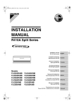
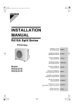
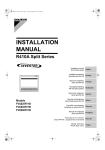
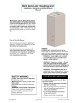
00_CV_3P155380-1E.fm Page 1 Friday, January 12, 2007 4:23 PM INSTALLATION MANUAL BP (Branch Provider) Unit Installation manual BP (Branch Provider) Unit English Installationsanleitung BP-Gerät (Abzweigdose) Deutsch Manuel d’installation Unité BP (Fournisseur de branchement) Français Montagehandleiding BP (Branch Provider) Unit Manual de instalación Unidad BP (Proveedor de ramificaciones) Models BPMKS967A2B BPMKS967A3B BPMKS967B2B BPMKS967B3B Manuale d’installazione Unità BP (Branch Provider) Εγχειρßδιο εγκατÜστασηò ΜονÜδα BP (ΠαροχÝαò ÄιακλÜδωσηò) Manual de Instalação Unidade BP (Fornecedora de Ramificação) Рóêоводство по óстановêе BP-блоê (блоê провайдера ветви) Nederlands Español Italiano ΕλληνικÜ Portugues Рóссêий BPMKS967A2B, BPMKS967A3B, BPMKS967B2B, BPMKS967B3B 2SB63219-37N Noboru Murata Manager Quality Control Department Shiga, 1st of Oct. 2005 Umeda Center Bldg., 4-12, Nakazaki-Nishi 2-chome, Kita-ku, Osaka, 530-8323 Japan 01_EN_3P155380-1E.fm Page 1 Friday, January 12, 2007 4:25 PM Safety Precautions • Read these Safety Precautions carefully to ensure correct installation. • This manual classifies the precautions into WARNING and CAUTION. Be sure to follow all the precautions below: they are all important for ensuring safety. WARNING...............Failure to follow any of WARNING is likely to result in such grave consequences as death or serious injury. CAUTION...............Failure to follow any of CAUTION may in some cases result in grave consequences. • The following safety symbols are used throughout this manual: Be sure to observe this instruction. Be sure to establish an earth connection. Never attempt. • After completing installation, test the unit to check for installation errors. Give the user adequate instructions concerning the use and cleaning of the unit according to the Operation Manual. WARNING • Installation should be left to the dealer or another professional. Improper installation may cause water leakage, electrical shock, or fire. • Install the air conditioner according to the instructions given in this manual. Incomplete installation may cause water leakage, electrical shock, or fire. • Be sure to use the supplied or specified installation parts. Use of other parts may cause the unit to come to lose, water leakage, electrical shock, or fire. • Install the air conditioner on a solid base that can support the weight of the unit. An inadequate base or incomplete installation may cause injury in the event the unit falls off the base. • Electrical work should be carried out in accordance with the installation manual and the national electrical wiring rules or code of practice. Insufficient capacity or incomplete electrical work may cause electrical shock or fire. • Be sure to use a dedicated power circuit. Never use a power supply shared by another appliance. • For wiring, use a cable length enough to cover the entire distance with no connection. Do not use an extension cord. Do not put other loads on the power supply, use a dedicated power circuit. (Failure to do so may cause abnormal heat, electrical shock or fire.) • Use the specified types of wires for electrical connections from the BP unit to the indoor and outdoor units. Firmly clamp the interconnecting wires so their terminals receive no external stresses. Incomplete connections or clamping may cause terminal overheating or fire. • After connecting interconnecting and supply wiring be sure to shape the cables so that they do not put undue force on the electrical covers or panels. Install covers over the wires. Incomplete cover installation may cause terminal overheating, electrical shock, or fire. • If any refrigerant has leaked out during the installation work, ventilate the room. (The refrigerant produces a toxic gas if exposed to flames.) • After all installation is complete, check to make sure that no refrigerant is leaking out. (The refrigerant produces a toxic gas if exposed to flames.) • When installing or relocating the system, be sure to keep the refrigerant circuit free from substances other than the specified refrigerant (R410A), such as air. (Any presence of air or other foreign substance in the refrigerant circuit causes an abnormal pressure rise or rupture, resulting in injury.) • During pump-down, stop the compressor before removing the refrigerant piping. If the compressor is still running and the shut-off valve is open during pump-down, air will be sucked in when the refrigerant piping is removed, causing abnormal pressure in the freezer cycle which will lead to breakage and even injury. • During installation, attach the refrigerant piping securely before running the compressor. If the compressor is not attached and the shut-off valve is open during pump-down, air will be sucked in when the compressor is run, causing abnormal pressure in the freezer cycle which will lead to breakage and even injury. • Be sure to establish a ground. Do not ground the unit to a utility pipe, arrester, or telephone ground. Incomplete earth may cause electrical shock, or fire. A high surge current from lightning or other sources may cause damage to the air conditioner. • Be sure to install an earth leakage breaker. Failure to install an earth leakage breaker may result in electric shocks, or fire. CAUTION • Do not install the air conditioner in a place where there is danger of exposure to inflammable gas leakage. If the gas leaks and builds up around the unit, it may catch fire. • This unit is for indoor use. (If installing outdoors, place in a location away from wind and rain.) 1 English 01_EN_3P155380-1E.fm Page 2 Friday, January 12, 2007 4:25 PM System Layout For installation of the indoor and outdoor units, follow the instructions in the Installation manual for each unit. BP unit model FOR 3 rooms : BPMKS967A3B, BPMKS967B3B FOR 2 rooms : BPMKS967A2B, BPMKS967B2B Indoor unit side piping Do not connect more than 9 indoor units together. Choose the BP unit type (2 rooms or 3 rooms) according to the installation pattern. Earth leakage breaker BP Unit Outdoor unit side piping Branch switch overcurrent breaker (fuse) Power BP Unit REFNET joint KHRQ22M20T or KHRP26M22T (Can be purchased separately.) BP Unit OUTDOOR UNIT INDOOR UNIT Max. 9 rooms Power voltage Power Earth leakage breaker Outdoor unit Total capacity of Indoor units Maximum quantity of Indoor units RMX(K)S112 RMX(K)S140 RMX(K)S160 55-145.5 70-182 80-208 6 8 9 The number of indoor units which can be connected varies depending on the power of the outdoor unit. See the table left for details. Note that the total indoor capacity per BP unit is as shown in the table below. Branch switch overcurrent breaker (fuse) Power voltage Power supply line (3 wires) English BP unit Maximum capacity BPMKS967A2B BPMKS967B2B 142 BPMKS967A3B BPMKS967B3B 208 [Example] For “FTXS50BVMB”, the capacity of this indoor unit is 50. ~ 50Hz 230V *Outdoor unit and all BP units require their own power supply. Piping Transmission line (2 wires) Brazing connection Power supply and transmission line (4 wires) Flare connection 2 01_EN_3P155380-1E.fm Page 3 Friday, January 12, 2007 4:25 PM Accessories 6 For indoor unit side piping (gas) 1 Installation Manual (pipe joint) 1pc. 2 For outdoor unit side piping (gas) BPMKS967A3B BPMKS967B3B (For 3 rooms) : 3pcs. BPMKS967A2B BPMKS967B2B (For 2 rooms) : 2pcs. 7 Hanger metal (pipe joint) 1pc. 3 For outdoor unit side piping (gas) 4pcs. 8 Screws (pipe joint) 1pc. 4 For outdoor unit side piping (liquid) 8pcs. 9 Binding band (pipe joint) 1pc. 2pcs. 1pc. BPMKS967A3B BPMKS967B3B (For 3 rooms) : 4sets BPMKS967A2B BPMKS967B2B (For 2 rooms) : 3sets 5 For Mindoor unit side piping (liquid) 10 Heat insulation (2pcs. is 1set) (pipe joint) Items to be prepared in the field • • • • • • Connecting wires between BP unit and indoor unit (H05VV(*), 4 wires, 1.6mm or 2.0mm) Connecting wires (H05VV(*), 3 wires, 1.6mm or 2.0mm) Transmission wires (H05VV(*), 2 wires, 0.75mm² to 1.25mm²) Installation parts (hanging bolts: 4 × M10 or M8; nuts: 8; flat washers: 8) Screws for wall-mounting: 6 × M5 Heat insulation (joint) [Thermal conductivity: 0.041 - 0.052W/mK (0.035 - 0.045kcal/mh°C) / thickness 13mm (1/2 inch) or more / Heat resistance: 100°C or higher] (*) Only in protected pipes, use H07RN-F when protected pipes are not use. Specifications for local wiring power cord and branch wiring are in compliance with IEC60245. Precautions for Selecting the Location The BP unit is for indoor use. Install in a location such as above a ceiling or behind a wall in accordance with the following conditions: • That the unit is fully supported, and is in a location with little or no vibration. • That the refrigerant pipes for the indoor and outdoor units can be repaired with ease, and that the units are placed well within the distance from each other allowed by the pipe length. • That there is nothing nearby that produces heat or steam (gas). • When installing, that there is enough room for servicing the unit. • Do not install in location that is hot or humid for long periods of time. A location where the dry-bulb (DB) temperature around the BP unit reaches 60°C or higher. • A well-ventilated area. • Do not install near bedrooms. The sound of refrigerant flowing through the piping may sometimes be audible. For restrictions on installation, refer to P5~6. “Installation”. 3 English 01_EN_3P155380-1E.fm Page 4 Friday, January 12, 2007 4:25 PM Installation Branch with refnet joint Example of connection (Connection of 8 units heat pump system) 1 indoor unit a BP 1 BP unit H2 A b c A B d refrigerant branch kit (refnet joint) e H1 BP 1 f i g 1 BP 3 BP 2 H3 j 4 l k 5 6 m 7 2 8 H4 h 3 Maximum allowable length Allowable height Pipe length between outdoor and BP units ≤ 55m Between outdoor and BP units Total piping length Between BP and indoor units Total piping length Between BP and indoor unit 1 room length Between outdoor and indoor units Difference in height Difference in height between outdoor and indoor units (H1) ≤ 30m Between outdoor and BP units Difference in height Difference in height between outdoor and BP units (H2) ≤ 30m Between BP and BP units Difference in height Difference in height between BP unit and BP units (H3) ≤ 15m Between indoor and indoor units Difference in height Difference in height between indoor and indoor units (H4) ≤ 15m Piping length between BP and indoor unit ≤ 15m [Example] f, g, h, i, j, k, l, m ≤ 15m Pipe length between outdoor and first refrigerant branch kit (refnet joint) ≥ 5m Piping length [Example] a ≥ 5m Allowable length after the branch ∗2 Branch kit are recommended to set as possible as near the BP units. c, d, e are recommended to be as possible as short. Piping length between BP and indoor units: RMX(K)S112 ≤ 60m / RMX(K)S140 ≤ 80m / RMX(K)S160 ≤ 90m [Example] RMXS140: f+g+h+i+j+k+l+m ≤ 80m Minimum allowable length ∗1 Since the sound of refrigerant may be transferred from the outdoor unit to the indoor unit, make the pipe length from the outdoor unit to the first junction 5m or longer. [Example] a+b+c+d+e ≤ 55m Piping length from first refrigerant branch kit (refnet joint) to indoor unit ≤ 40m Piping length [Example] unit 8: b+c+m ≤ 40m [Example] unit 6: b+e+k ≤ 40m [Example] unit 3: d+h ≤ 40m Refrigerant branch kit selection (refrigerant branch kits can only be used with R410A) Refrigerant branch kit (refnet joint) name: KHRQ22M20T or KHRP26M22T Piping size selection • Piping size (Outer diameter × minimum thickness) symbol Gas pipe Liquid pipe Between outdoor unit and first refrigerant branch kit a φ19.1 × 1.0 φ9.5 × 0.8 Between first refrigerant branch kit and the other branch kit b φ15.9 × 1.0 φ9.5 × 0.8 Between refrigerant branch kit and BP unit c, d, e Table A Total indoor capacity Q Qc, Qd, Qe ≤ 5.0kw Qc, Qd, Qe > 5.0kw Gas pipe φ12.7 × 0.8 φ15.9 × 1.0 See the table A Liquid pipe φ6.4 × 0.8 φ9.5 × 0.8 ∗Qc, Qd, Qe is total connected indoor capacity ∗Subscript c, d, e indicates the above symbol [Example] indoor 4: 2.5kW indoor 5: 3.5kW Qe = 11.0kW indoor 6: 5.0kW => (Gas pipe) φ15.9 × 1.0 / (Liquid pipe) φ9.5 × 0.8 English 4 01_EN_3P155380-1E.fm Page 5 Friday, January 12, 2007 4:25 PM Installation • This unit may be installed suspended from the ceiling or mounted on the wall. • This unit may only be installed, as shown in the diagram below. (The side should be facing upwards.) However, it may be freely installed in any direction forward or back, and to the sides. • Be sure to leave a 650mm square opening for service and inspection as shown in the diagram below, for both ceilingsuspended installation and wall-mounted installation. • This unit “does not require drain treatment”. • This unit may be installed with sides or facing forward (servicing direction). • The piping for the indoor unit may be freely led around in directions , , or . • The inclination of side must be within ±5 degrees forward or back or to the sides. For 2 rooms Wall-mounted Manufacturer’s label 4-Suspension bolt (M8-M10) 254 (304) 25 Indoor unit side piping Suspension bolt pitch 2×2-Brazing (304) Terminal (For A room) Terminal (For B room) Wiring clamp 95 322 Suspension bolt pitch Wiring clamp Electric box (Top surface) Terminal (For transmission) 2-I.D. φ15.9 CuT I.D. φ19.1 CuT Room B Room A 73.5 23 23 73.5 (180) 57 45 113 (25) (product dimensions and attachment bolt pitch) 2-I.D. φ6.4 CuT Earth (M4) 178 INDOOR UNIT SIDE Terminal (For Power supply) 294 (650) Installation restrictions Earth (M4) 178 2-Brazing 197 I.D. φ9.5 CuT 107 OUTDOOR UNIT SIDE Standard accessories (Installation and service space) (Servicing space) Min 390 Min 390 68 163 For indoor unit side (Gas) 165 90 (125) 30 155 85 (70) O.D. φ15.9 For outdoor unit side (Gas) O.D. 110 Dimple φ19.1 65 I.D. φ9.5 I.D. φ19.1 5 45 Cut line for I.D. φ15.9 Cut line for I.D. φ12.7 For outdoor unit side (Gas) Min 300 (Servicing space) Cut line for 110 (Servicing space) The opening for Inspection Servicing is needed opening of 650mm square for service and maintenance. O.D. φ15.9 90 For indoor unit side (Liquid) Cut line for O.D. φ6.4 I.D. 150 φ12.7 For outdoor unit side (Liquid) O.D. φ9.5 100 I.D. φ6.4 I.D. φ9.5 English 01_EN_3P155380-1E.fm Page 6 Friday, January 12, 2007 4:25 PM For 3 rooms Wall-mounted Manufacturer’s label 4-Suspension bolt (M8-M10) 254 (304) 25 Indoor unit side piping Suspension bolt pitch 2×3-Brazing (304) Wiring clamp 95 57 95 3-I.D. φ15.9 CuT 322 Suspension bolt pitch Terminal (For A room) Terminal (For B room) Terminal (For C room) Terminal (For transmission) Wiring clamp Electric box (Top surface) I.D. φ19.1 CuT Room C Room B Room A 73.5 23 23 73.5 (180) 57 45 113 (25) (product dimensions and attachment bolt pitch) 3-I.D. φ6.4 CuT Earth (M4) 178 INDOOR UNIT SIDE Terminal (For Power supply) 294 (650) Installation restrictions Earth (M4) 178 2-Brazing 197 I.D. φ9.5 CuT 107 OUTDOOR UNIT SIDE Standard accessories (Installation and service space) For indoor unit side (Gas) I.D. φ9.5 I.D. φ19.1 English 45 Cut line for I.D. φ15.9 Cut line for I.D. φ12.7 For outdoor unit side (Gas) Min 300 (Servicing space) Cut line for 110 165 90 O.D. φ15.9 For outdoor unit side (Gas) O.D. 110 Dimple φ19.1 65 (125) 68 163 258 30 Min 390 85 (70) (Servicing space) Min 460 155 (Servicing space) The opening for Inspection Servicing is needed opening of 650mm square for service and maintenance. O.D. φ15.9 90 I.D. φ12.7 For indoor unit side (Liquid) Cut line for O.D. φ6.4 150 For outdoor unit side (Liquid) O.D. φ9.5 100 I.D. φ6.4 I.D. φ9.5 6 01_EN_3P155380-1E.fm Page 7 Friday, January 12, 2007 4:25 PM Installation of the Unit 1. Replacing the printed circuit board • This unit has two different installation types: (1) ceiling-suspended type and (2) wall-mounted type. • Choose the proper installation pattern according to the location of installation. • The installation location for the printed circuit board can be changed. • Procedure for changing the installation location of the printed circuit board. If the installation location of the printed circuit board needs to be changed because of the installation conditions, perform the following: Printed circuit board To opposite side Printed circuit board Indoor unit side pipe As-shipped condition After-location is changed Caution • Before doing any wiring on site, replace the printed circuit board. 1) Remove the screws and pull off the electrical equipment cover. Screw (M4×12L) 2) Remove 4 screws shown in the figure on the below, remove the printed circuit board. Electrical equipment cover Remove 4 screws. (M4×8L) 4 4 4 P 4 3) Remove the binding band (A) which holds the wires. Binding band Printed circuit board (A) (B) Press on the protrusion and pull out. 4) Remove the printed circuit board, and reattach as shown in the figure. Top surface of the unit Lift the tabs. To opposite side 5) Reattach the binding band to position (B). Printed circuit board (A) (B) Binding band 7 English 01_EN_3P155380-1E.fm Page 8 Friday, January 12, 2007 4:25 PM 6) Attach the printed circuit board and electrical equipment cover to the other side and secure with the screws. Printed circuit board Electrical equipment cover Top surface of the unit Insert the tabs fully. 2. Ceiling-suspended type Hanger metal 7 Procedure: 15~20 1) Fix the furnished hanger metal 7 with two screws 8 . (4 locations in total) 2) Using an insert-hole-in-anchor, hang the hanging bolt. 3) Install a hexagon nut and a flat washer (field supply) to the hanging bolt as shown in the figure in the below, and lift the unit to hang on the hanger metal. 4) After checking with a level that the unit is level, tighten the hexagon nut. * The tilt of the unit should be within ±5° in front/ back and left/right. Screws 8 Ceiling side Hanging bolt (M10 or M8) Six-sided nut (M10 or M8) Flat washer Nut Flat washer Hanger metal 7 Hanging bolt 3. Wall-mounted type BP unit Screws 8 Hanger metal 7 Procedure: 1) Fix the furnished hanger metal 7 with two screws 8 . (4 locations in total) 2) Create a gap with the wall and screw in the temporary screws (M5, field supply), and hang the BP unit. 3) After checking with a level that the unit is level, fix the unit with screws (M5, field supply). * The tilt of the unit should be within ±5° in front/ back and left/right. Screws 8 Hanger metal 7 Screws (M5) (field supply) CAUTION • Be sure to install the unit with the top surface up. • Do not install near bedrooms. The sound of refrigerant flowing through the piping may sometimes be audible. Temporary screw (M5, field supply): Screw in temporarily after opening a slight gap with the wall. Temporary screws: attach and then hang the unit on them. (2 screws) Screws (M5) (field supply) : screw for fixing. (4 places) English 8 01_EN_3P155380-1E.fm Page 9 Friday, January 12, 2007 4:25 PM Connection of Refrigerant Piping See the indoor and outdoor units installation manual for details on the size of connection piping to the indoor and outdoor units. 1. About brazing pipes on site 1) Before brazing, remove the heat insulation. 2) Remove the blue-colored tape, and throw it out. Heat insulation 10 3) Wrap the pipes to be brazed with sufficient wet cloths so that brazing does not affect the unit. 4) After brazing, use wet cloths or spray mist to sufficiently cool off all pipes. 5) When brazing, be careful that the flame of the torch does not come in contact with the unit. (Since the inside of the unit is made of plastic, it may become deformed or melt, destroying its heat-insulation performance.) Wet cloth brazing Wet cloth 2. Insulation of pipes 1) Attach heat insulation to each pipe. 2) When attaching insulation to the pipes, use one-sided adhesive tape or similar materials to thoroughly prevent air from entering the heat insulation. 3) Eliminate any gaps in the heat insulation. One-sided adhesive tape (field supply) Heat insulation (field supply) Heat insulation 10 3. Unconnected pipes 1) For pipes not yet connected to a room, pinch the end of the pipe and braze them. 2) When brazing this area too, wrap the pipes with sufficient wet cloths to protect the unit. 3) After brazing this area too, cool the pipes sufficiently. Wet cloth brazing Wet cloth brazing 4) Attach heat insulation, and use one-sided adhesive tape to thoroughly prevent air from entering the heat insulation. 5) Cover the ends of the pipes with sufficient heat insulation. One-sided adhesive tape (field supply) Heat insulation (field supply) 9 English 01_EN_3P155380-1E.fm Page 10 Friday, January 12, 2007 4:25 PM • After brazing and system leakage check, connect a heat insulation (field supply), and let it cure completely following the procedure illustrated right. Use the heat insulation with the following specifications: Thermal conductivity: 0.041-0.052W/mK (0.0350.045kcal/mh°C) / thickness 13mm or more Heat resistance = 100°C or higher • To ensure that the weight of the local interunit piping does not bear on directly on the BP unit, secure it near the BP unit using the clasp (field supply). Heat insulation (field supply) Heat insulation (field supply) Heat insulation 10 Clasp (field supply) Clasp (field supply) BP unit Indoor unit side piping Outdoor unit side piping Place the heat insulation up against the BP unit to prevent any gaps from forming between the two, and wrap with masking tape as shown in the figure. • When connecting indoor units, make sure to connect refrigerant pipes and connection wires to the appropriate connection ports marked with matching alphabets (A, B and C). Hanger metal 7 Room A (Gas) Room B (Gas) Room C (Gas) Room A (Liquid) Room B (Liquid) Room C (Liquid) 〈View from the indoor unit〉 • When changing the routing direction, use the pipe joints 2 and 6 (accessories). Use pipe joints 3 , 4 and 5 to connect refrigerant pipes with different diameters. Indoor unit side (Gas) Outdoor unit side (Gas) 30 Brazing 125 I.D φ9.5 I.D φ12.7 Piping Pipe joint 3 (field supply) Piping (field supply) Brazing (125) When straight. Cut line for I.D φ15.9 110 Pipe joint 6 Brazing Piping (field supply) Pipe joint 2 I.D φ9.5 Cut line for I.D φ12.7 Pipe joint 6 Cut line for straight (70) 85 Cut line for I.D φ12.7 Piping (field supply) When the direction is changed. Brazing I.D φ15.9 Brazing Connection for φ15.9 piping. I.D φ12.7 Connection for φ12.7 piping. When straight. 45 Indoor unit side (Liquid) Pipe joint 5 Piping (field supply) Pipe joint 2 Brazing I.D φ9.5 Piping (field supply) Cut line for I.D φ15.9 Piping (field supply) I.D φ19.1 Pipe joint 3 Connecting φ9.5 interunit piping (65) Brazing 45 Cut line for O.D φ6.4 Outdoor unit side (Liquid) I.D φ12.7 Brazing Cut line for I.D φ15.9 Connection for φ19.1 and φ15.9 piping. Connection for φ12.7 piping. When the direction is changed. Pipe joint 4 Piping (field supply) Brazing I.D φ6.4 Connecting φ6.4 interunit piping English NOTE When changing the direction of the piping to something other than the above, bend the piping on site. 10 01_EN_3P155380-1E.fm Page 11 Friday, January 12, 2007 4:25 PM Connecting the Wiring Connection example of total system wiring Indoor unit The following kind of wiring methods is okay for the power line. Pattern 1 Indoor unit BP unit Power Indoor unit Earth leakage breaker N2 L2 BP unit N1 3 L1 Pattern 2 Power voltage N2 L2 BP unit N1 3 L1 Power voltage N2 L2 BP unit N1 2 L1 Power voltage N2 L2 BP unit N1 1 L1 Outdoor unit Indoor unit Branch switch overcurrent breaker (fuse) N2 L2 BP unit N1 2 L1 BP unit Indoor unit Power voltage Indoor unit 16V BP unit Indoor unit Power Ground Earth leakage breaker Indoor unit Power voltage N2 L2 BP unit N1 1 L1 • Crossover wiring is possible for the power line. Branch switch overcurrent breaker (fuse) Power voltage • It is also possible to supply power from the BP units themselves. CAUTION • Be sure to connect the power line to L1 and N1. • For crossover wiring, take the line from L2 and N2 and connect it to L1 and N1 on the other BP unit. Ground Work procedure Electrical equipment cover 1) Remove the screws and pull off the electrical equipment cover. Screw (M4×12L) 2) Tape is attached to the wire binding band. The purpose of the tape is to prevent small animals from entering the unit. Only remove the tape from places where wiring it to be passed through. CAUTION 4 If the tape is not replaced for places where wiring will not pass through, small animals may enter, causing product malfunction. 4 4 4 P The tape to prevent the entry of small animals The tape to prevent the entry of small animals 11 Wire clamp The tape to prevent the entry of small animals (tape is attached when unit is shipped to prevent animals from entering the unit) Wire clamp English 01_EN_3P155380-1E.fm Page 12 Friday, January 12, 2007 4:25 PM 3) Follow the instructions on the wiring nameplate to connect the connection wires of indoor/outdoor units to terminal block numbers. (1, 2, 3, F1 and F2) Always fix each ground wire separately with a ground screw. (See the figure below.) NOTE: The terminal block numbers are arranged from top to bottom in order of 1, 2 and 3. Peel the outer coating leaving 10mm from the wire clamp. 10mm Example 〈For 3 rooms〉 Binding band 9 Secure the wires with binding band 9 to prevent them from coming out if pulled on from the outside. Wire clamp Transmission wire (To other BP unit: F1, F2) P N2 L2 N1 L1 1 2 Room C 3 Ground Transmission wire (To other BP unit: F1, F2 or to outdoor unit: F1, F2) H05VV(*), 2 wires 0.75mm2 to 1.25mm2 Wire clamp F2 F1 *Fix each wire separately. 4 4 1 2 Room B 3 For other BP unit (To L1, N1) CAUTION 4 4 Connection wire for indoor units. H05VV(*), 4 wires 1.6mm or 2.0mm 1 2 Room A 3 Warning Do not use tapped wires,stand wires, extensioncords, or starbust connections, as they may cause overtheating, electrical shock, or fire. Mistakenly connecting the power supply to this terminal block could cause control operating malfunctions. Power supply wire for indoor units. H05VV(*), 3 wires 1.6mm or 2.0mm Safety breaker Earth leakage 16A or 15A circuit breaker When wire length exceed 10m, use 2.0mm wires. Power supply ~50Hz 230V (*) Only in protected pipes, use H07RN-F when protected pipes are not use. Specifications for local wiring power cord and branch wiring are in compliance with IEC60245. CAUTION • All local interunit wiring must be secured using the wire binding band over the insulation, as shown in the figure. Insulation • When connecting the connection wires to the terminal block using a single core wire, be sure to perform curling. Problems with the work may cause heat and fires. Wire binding band 4) Allow 300mm for the pulling-out section of harness. +300mm of slack +300mm of slack 5) Return the electrical equipment cover to its original position, and fix it with the screws. Screw (M4×12L) Install the electrical equipment cover. English 12 01_EN_3P155380-1E.fm Page 13 Friday, January 12, 2007 4:25 PM Operating Test Follow the “Operating test” as described in the installation manual of the outdoor unit. If the BP unit does not operate normally during the test run, the error can be checked on the remote controller display for the indoor unit. Error codes displayed on the remote controller Malfunction code Nonconformity during installation Remedial action A9 Electric expansion valve connector not connected (BP unit) E2 Printed circuit board faulty (BP unit) J0 Liquid and gas thermistor faulty (BP unit) U4 Transmission error between BP unit and indoor unit Connect correctly the interconnections between BP unit and indoor unit. U9 Transmission error between outdoor unit and other BP unit Connect correctly the interconnections between outdoor and other BP unit. UJ Transmission error between outdoor unit and this BP unit connecting with the indoor unit of error code displayed Connect correctly the interconnections between outdoor and this BP unit connecting with the indoor unit of error code displayed. Please contact your dealer. The BP Unit Simple diagnosis can be done using the LEDs on the BP unit’s circuit board. For details, see the label on the inside of the BP unit’s electrical equipment cover. 13 English 00_CV_3P155380-1E.fm Page 2 Friday, January 12, 2007 4:23 PM Two-dimensional bar code is a code for manufacturing. 3P155380-1E M04B237D (0701) HT