1
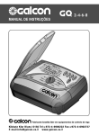
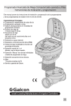
Battery Operated Advanced Computerized Irrigation
Controller Installation and Operating Instructions
This handbook provides the installation and operating instructions for
the DC-1 and DC-4 controllers.
Main Features:
• Independent programming of each
individual valve
• Weekly or cyclical programming
• Up to 4 operations per day in weekly
program mode
• Irrigation duration one minute to
12 hours
• Irrigation frequency once a day to once
every thirty days in a cyclical program
• Waterproof when immersed in water
(IP68)
• Rain off sensor option
• Weather resistant
• Irrigation duration modifiable as a
function of percentage entered
• Operation of one to 4 valves and a
master valve
• Computerized "manual" operation of
individual valves
• Sequential “manual” operation - optional
• Batteries: DC-1-4: two 9V alkaline
batteries
Computerized Control Systems
Contents
1 Parts Identification...................................................................................3
2 Setting up the Irrigation Controller.................................................................3
2.1 Valve and Solenoid Assembly
2.2 Manual-Mechanical Operation
2.3 Battery Installation
2.4 Installing the Controller in the Irrigation System
2.5 Wiring the Solenoids
3 Programming the Irrigation Controller.......................................................7
3.1 Setting the Current Time and Day of the Week
3.2 Switching between AM/PM and 24 Hour Time Format
3.3 Valve Selection
3.4 Setting the Irrigation Duration
3.5 Selecting Days of the Week for Irrigation
3.6 Setting Irrigation Start Times
3.7 Example: Programming a Weekly Irrigation Schedule
4 Additional Functions................................................................................12
4.1 One-Time Irrigation
4.2 Cyclical Irrigation
4.3 Setting the Day of the Week and Time for Cyclical and One-Time
Irrigation Programs
4.4 Irrigation Window In the Cyclical Program Mode
4.5 Opening an Irrigation Window after Start Time has passed
4.6 Example: Programming a Cyclical Irrigation Schedule
4.7 "Manual" Irrigation System Operation via the Irrigation Controller
4.8 Sequential "Manual" Operation of all the Valves
4.9 Suspension
4.10 Irrigation Duration Extended or Shortened by a
Specified Percentage
5 Additional Displays...................................................................................16
5.1 Valve in Wait Mode
5.2 Blinking Low Battery Warning
5.3 Permanent Low Battery Warning
5.4 Missing Program Data
5.5 Sensor
6 Maintenance, Troubleshooting and Repairs............................................19
7 Additional Accessories and Products.....................................................20
8 Table for Irrigation Planning with Galcon Controllers........................21
1. Parts Identification
1. Cover
2. Push buttons
3. Controller display
4. Battery compartment cover
5. Solenoid
6. Mechanical operation lever
7. Bayonet adapter
8. Hydraulic valve
Important!
Assembly of a filter upstream of the
valve is mandatory.
(See list of accessories page 20).
2. Setting up the
Irrigation Controller
2.1Valve and Solenoid Assembly
2.1.1 Shut the main irrigation system valve.
2.1.2 Install the hydraulic valve in the
irrigation system.
2.1.3 If necessary, remove the solenoid [1]
from the bayonet adapter by making a
quarter turn to the left.
Note: Be careful not to lose the
seal (O-ring) [2] and assemble the
solenoid with the manual lever
(see illustration).
After installing the hydraulic valve [3],
assemble the solenoid (if you removed it)
by making a quarter turn to the right.
2.1.4 Be sure to correctly position the seal
(O-ring) [2] in place.
Important!
It is recommended that you do not disassemble the bayonet adapter.
2.2 Manual-Mechanical Operation
mechanical
operation
lever
The irrigation valve can be opened and closed
independent of the controller's operation.
Manual operation is useful when immediate
irrigation is required, and there is insufficient
time or knowledge to program the controller.
The valve lever is located on the solenoid,
and has three positions (from left to right):
Open, Automatic [AUTO] and Closed.
Remember! For controller operated irrigation, the
valve lever must be in the middle (AUTO) position.
2.3 Battery Installation
Open the battery compartment cover.
Insert batteries (see illustration). All the
controller display elements appear briefly
on the display, followed by a blinking time
of 12:00. The controller is now ready to
be programmed.
Important!
Make sure to replace the battery
compartment cover with the grip (see
drawing) and then rotate the cover 1/8 of
a turn to the right.Be sure to do so
otherwise the battery cover pins might
break.
close
closed
2.4 Installing the controller in the
irrigation system
The controller can be installed on the
solenoid or on the wall.
Installing on the solenoid
a. Remove the solenoid (5) with a 1/4 turn.
b. Pass the solenoid through the
connector, and connect back into place.
Important: Make sure the Oring is in
place and the lever is in the direction
as shown in drawing.
c. Install the solenoid connector (4) onto the solenoid
(5) and fasten with screw (3) parallel to the valve.
d. Remove the bracket (2) from the controller and
slide the bracket onto the solenoid connector.
e. Connect the controller onto the bracket by
pressing.
Installing on the wall
a. Place the mounting plate (6) on the wall using
3 screws (not included).
b. Remove bracket (2) from controller and slide
onto the mounting plate.
c. Connect the controller to
the bracket (2) by pressing.
(1) Controller
(2) bracket
(3) Screw
(4) Solenoid connector
(5) Solenoid
(6) Mounting plate for wall
6
5
S
Labeled cables (1) emerge from the controller. The end of each cable is protected by
a cover that must be removed prior to connecting the cable. The cables are specifically
designed to connect to Galcon DC type irrigation valves and solenoids (3).
The controller and its connections are waterproof. To safeguard the waterproof
characteristics, compliance with the following is essential:
• Do not remove protective covers from cables that are not connected to valves.
Exposed cable ends can short-circuit with each other, with conducting bodies and
in water.
• Connect the cables to the valves (3) using the special waterproof connectors (2)
supplied with the product. See illustration.
1. Cut away the covering from the controller cable (1) near the end of the cable and
expose the cable leads from the black insulating outer sleeve. The solenoid cables
have three wires: white, red and black. Do not expose the three wires from their
colored insulation.
2. Connect the leads to waterproof connector (2)
3. Programming the Irrigation Controller
This section describes the programming steps for a simple irrigation schedule.
It is followed by a section dealing with more advanced irrigation controller
operations.
The irrigation controller is programmed with the aid of 4 buttons:
Programming Step Selector - used to select the desired programming
mode (e.g., clock setting mode)
Parameter Selection Button - used to select the parameter to be
changed (e.g., hour, minute, etc.). The selected parameter can only be changed when
its entry is blinking on the display.
Increment Button - increases the value of the selected parameter (e.g.,
when hour is selected, from 06:00 to 07:00).
Decrement Button - decreases the value of the selected parameter
(e.g.,when hour is selected, from 06:00 to 05:00).
3.1 Setting the Current Time and Day of the Week
To enable the irrigation controller to operate
the irrigation system at the correct times, the
current time and current day of the week must
first be set.
1. Press
several times until the appears.
2. Press The hour digits blink. Set the
current hour using or (Note the AM and
PM designations).
3. Press The minute digits blink. Set the
or .
current minute using
4. Press A blinking arrow appears at the
top of the display. Move the arrow to the
current day of the week using the
or
button.
If the most recent data item stops blinking before you finish programming it,
to continue the programming process.
press
7
3.2 Switching between AM/PM
and 24 Hour Time Format
The default time format is AM/PM. There is
also a 24 hour time format. To switch
between the two formats:
until the
appears.
1. Press
2. Press
The hour digits blink.
and
simultaneously. The
3. Press
clock reading switches from AM/PM to a 24
hour time display or vice versa.
You can switch the time display
format at any step in the
programming process.
3.3 Valve Selection
This section does not apply to the
DC-1 model.
Program an irrigation schedule for each valve
individually. First select the desired valve, and
then program a schedule as follows:
1. Press
until
appears.
2. Press . A blinking arrow appears at the
bottom of the display.
3. Move the arrow to the desired valve number
by pressing or .
4. Press to proceed to the next step.
8
3.4 Setting the Irrigation Duration
This setting determines how long the irrigation
lasts.
1. Press until appears.
2. Press . The hour digits blink. Set the
desired number of hours by pressing
or . Press again - the minute digits
blink. Set the desired number of minutes
by pressing or .
3. Press to proceed to the next step.
3.5 Selecting Days of the Week for Irrigation
This setting determines which days of the week the irrigation controller will operate
the specified valve.
1. Press until
appears.
2. Press . A blinking arrow appears at the
top of the display, under Monday.
3. Move the blinking arrow to the desired day
of the week by pressing .
4. Selecting/adding irrigation days:
Press . The arrow under the selected
day stops blinking, moves one position to
the right, and blinks under the next day of
the week.You can select additional days
of the week in the same manner.
5. Canceling Scheduled Irrigation Days:
Have the arrow blink under the day you
want to cancel. Press . The arrow under
the selected day will disappear. The blinking arrow will move one position to the
right, under the next day of the week. Cancel additional scheduled irrigation days
in the same manner.
6. Press to proceed to the next step.
• When the blinking arrow reaches Sunday, pressing again displays OnCe in the center
of the display, and
at the top right of the display. To return to the "Selecting/Adding
Irrigation Days" mode, press once or twice.
9
3.6 Setting Irrigation Start Times
In this step, up to 4 separate irrigation start
times can be programmed for a selected day
for the valve being programmed. The selected
valve will open at each of the start times set,
for the irrigation duration set as described in
Section 3.4.
1. Press until the START I appears.
The word OFF or the last start time set
will appear on the display.
2. Press . The displayed item blinks
or last start time entered).
(
3. Set the desired start time by pressing
or . (Take note of the AM and
PM designations). Repeat actions 2 and
3 to set start times II, III and IV, as needed.
4. To cancel a specific start time, select it by
pressing . Next, press . The hour
digits blink. Press or until the word
appears on the display.
5. To program another valve, select it, and
repeat the above steps, starting from
section 3.3 above.
10
3.7 Example: Programming a Weekly Irrigation Schedule
Let's assume you want to program the irrigation controller to water three times
a day using the 24 hour time display format: at 08:00 AM, 13:00 PM and 19:00
PM, for 21/2 hours at a time, on Tuesday and Friday.
To switch to an AM/PM time display format, see section 3.2.
(If you are using a DC-1 model irrigation controller, start from step 4 below.)
1. Press until
appears.
2. Press . A blinking arrow appears at the bottom of the display.
3. Press or to move the arrow to the valve number to be
programmed.
4. Press until appears.
or until the hour displays 2.
5. Press . The hour digits blink. Press
Press . The minute digits blink. Press or until the
minute displays - 30.
6. Press .
appears.
7. Press . A blinking appears at the top of the display, under Monday.
Press until the blinking arrow appears under Tuesday, and then press .
The arrow under Tuesday will stop blinking and advance one position to the
right, to Wednesday. Press twice to move the arrow to Friday, and then
press .
8. Press . START I time appears. Press . The hour digits blink.
9. Set the start time to 08:00 by pressing or .
Repeat this step to set START II time [2] to 13:00 and START III time [3]
to 19:00.
10. Press . START IV time [4] appears. Press . The hour digits blink.
appears. The fourth opening of the valve is canceled.
11. Press or until
11
4. Additional Functions
4.1 One-Time Irrigation
This function is used to program the irrigation
controller to operate the irrigation system
once only, for the set irrigation duration, at
the set time.
(Duration set as described in Section 3.4).
1.Press
until
appears.
2.Press several times (for all the days
appears, and
of the week) until
blinks on the display.
3.Go to Section 4.3 to set the day and time.
4.2 Cyclical Irrigation
This option is used to program the irrigation
controller to operate the irrigation system in
a cyclical manner, once every x days, for the
irrigation duration.
(Note: Duration for which valve stays open
set as described in Section 3.4).
1. Press until
appears.
2. Press several times (for all the days
appears, and
of the week) until
blinks on the display.
3. With the display blinking, press or . The interval between irrigation sessions
(irrigation cycle) in days, hours or minutes is displayed. For example, if you set 2
days, the irrigation will be performed every two days for the defined duration.
12
4.3 Setting the Day of the Week
and Time For Cyclical and One-Time
Irrigation Programs
These programs enable you to pre-set the time
of valve opening. The number of days until the
valve opening appears on the display, to the
right of the irrigation start time (above the word
"days"). 0 days = program starts today; 1 day
= program starts tomorrow, etc. (up to 30 days).
1. Press
until START I appears. The last opening time entered appears
on the display.
2. Press . The hour digits blink.
3. Set the desired opening time by pressing or
(Take note of AM and PM
designations).
4. Press
until the digit to the right of the opening time blinks (The digit above the
word "days").
5. Set the number of days until the opening of the valve by pressing or .
• Valve openings 2, 3 and 4 are canceled in this mode.
4.4 Example: Programming a Cyclical Irrigation Schedule
Let's assume you want to program the irrigation controller to open the valve at 12:45
PM, for a period of one hour, every 5 days.
1. Set the irrigation duration as described in Section 3.4: Setting the Irrigation Duration.
(Press until appears, then set the desired irrigation duration by pressing
or ).
appears.
2. Press until
3. Press a number of times (for all the days of the week) until On CE appears blinking
on the display.
4. While the display is still blinking, press or until "5 days" appears on the display,
representing the irrigation frequency.
5. Press . START I is displayed.
6. Press . The hour digits blink.
7. Press until the hour digits change to 12 (PM).
8. Press until the minute digits change to 45.
13
4.5 "Manual" Irrigation System
Operation via the Irrigation
Controller
This function operates the selected valve for
the irrigation duration defined in the program.
The valve will close automatically at the end of
the irrigation duration.
Note that the originally programmed irrigation
schedule continues to operate at the set times.
appears. Select one or
1. Press until
more valves as described in Section 3.3:
"Valve Selection".
2. Press until appears.
3. Press to open the valve. The word "On"
is displayed. After an interval of 5 seconds,
a count down of the remaining irrigation
duration appears on the display.
To close the valve manually, press .
appears on the display.
4. To close the valve manually before the end
of the irrigation duration, press until ON
appears again on the display.
Press to close the valve.
Up to two valves can be operated
simultaneously in this manner. Simply repeat
the above steps for the second valve.
4.6 Sequential "Manual" Operation
of all the Valves
The valves can be operated sequentially, one
after the other.
1. Press until the
appears.
2. When nothing is blinking on the display,
press and hold down for 5 seconds.
Valve 1 will open and operate for the
programmed irrigation duration. When valve
1 closes, valve 2 opens, and so forth until
the last valve has opened. All the valves
designated to open blink.
3. You can control the process. Pressing
closes the current valve and opens the next
one.
Important: You can only exit this screen
after all the valves have opened.
14
4.7 Suspension
This option is used to temporarily suspend the
irrigation controller's control of the valves, for
example, while it is raining. The irrigation schedule
remains stored in the controller, but is not
implemented. The suspension option disables
ALL valves connected to the irrigation controller.
1. Press until the appears.
2. Press and hold down for 5 seconds.
appears blinking alongside the word "rain off".
The controller is now suspended.
3. To restore control to the controller,
press until the appears, and then press and hold down until the
disappears.
4. Suspension can also be implemented while a valve has been activated.
5. If an attempt is made to operate a valve manually while the irrigation controller has
been suspended, or when a valve is meant to open sequentially, the word "rAin"
appears on the display, and the valve will not open.
4.8 Irrigation Duration Extended or Shortened
by a Specified Percentage
You can extend / shorten the irrigation duration
for all the valves simultaneously by specifying a
percentage for the duration.
Example: if the irrigation duration has been set
to one hour, adding 10% extends the duration
by 6 minutes (to 66 minutes).
1. Press until the
appears.
2. Wait until no digit is blinking
3. Press and simultaneously. 00+% is
displayed.
4. Press
. The 00 blinks. Press or to
increase or decrease the percentage as
necessary (in increments of 5%). +% or -% is
permanently displayed on the main display,
accordingly.
Important! The percentage cannot be changed for an individual valve.
15
5. Additional Displays
5.1 Valve in Wait Mode
This section does not apply to the
DC-1 Model.
When two valves are currently open, and
a third valve is scheduled to open, the third
valve enters into wait mode. A blinking
appears above the number of the waiting
valve. When one of the first two valves
closes, the waiting valve opens. During
"manual" operation of a waiting valve via
the irrigation controller, the letter "W" (Wait)
appears on the display. The valve opens
when another valve closes.
5.2 Blinking Low Battery Warning
When the batteries are low, a blinking battery
icon appears on the display. In this state, the
batteries still enable valve operation, but must
be promtly replaced.
After replacing the batteries, press any button
to resume irrigation controller operation.
Programmed data are retained if batteries
are replaced within 30 seconds.
16
5.3 Permanent low battery
warning
When the batteries are low and not replaced
in a timely manner, the battery icon is
permanently displayed. All other display
elements disappear, all valves will close
and all programs will disappear.
Replace batteries promply and reprogram
the controller.
Programmed data are retained if batteries
are replaced within 30 seconds.
5.4 Missing Program Data
During "manual" operation via the irrigation
appears on the display
controller
(see Section 4.6: "Manual Irrigation System
Operation"), indicating that no irrigation
duration has been set for the specified
valve. In this case, opening of the valve is
disabled.
17
5.5 Sensor
The irrigation controller offers advanced
irrigation control using a rain off sensor. That
is, as long as the conditions defined for
activation of the sensor are not met, the
irrigation schedule will not be implemented.
(The rain off sensor contact remains closed).
For example, if a rain sensor is connected to
the irrigation controller, irrigation takes place
as long as the sensor remains dry. In the
event of rainfall, the sensor prevents the
opening of all the valves associated with it.
There is also the option of using any type of
dry contact sensor N.O. When the sensor
contact is closed all valves will close and no
irrigation will take place (diagram page 6).
As long as the sensor closes the circuit (i.e.,
the sensor detects the existence of a defined
program lockout condition) the symbol blinks
on the display and irrigation will not take place
through any valves associated with the sensor.
The display will show “S OFF” when the
controller is in manual operation. This means
the sensor is activated and prevents the
irrigation.
18
6. Maintenance, Troubleshooting and Repairs
• Batteries should be removed if the irrigation controller is not going to be used for a
lengthy period. The programs will disappear when removing batteries. Again
reprogram
the controller.
• A filter must be installed upstream of the valve or system of valves and cleaned every
few months. Operation without a filter is liable to lead to malfunctions.
• Under normal usage, batteries (Alkaline) last at least a year.
• Do not run water through an irrigation line unless a solenoid is fitted on the hydraulic
valve.
• Recommended water pressure: 1-8 ATM (bar).
Problem/Event
Cause
Valve does not open during
Valve lever not in
Automatic operation or during AUTO position.
"Manual" operation via
Batteries not working
irrigation controller
No display
Batteries not working
Solution
Move valve lever to
AUTO position.
Replace batteries
Replace batteries
Valve does not close, despite Valve lever not in AUTO
click heard during activation position.
Move valve lever to
AUTO position
Dirt and scale in valve mechanism Clean or replace valve
Water leak from the
solenoid-valve coupling
connection
20 mm or 5 mm seal (O-Ring)
between bayonet adapter and
valve missing (See illustration
below)
Install new seal (O-Ring)
1. 20 mm seal (O-Ring).
2. 5 mm seal (O-Ring).
19
7. Additional Accessories and Products
7.1 General
Lockable protective box
Line Filter, BSP 3/4”
Line Filter, BSP 1”
Waterproof connector
Extension cable for solenoid cables
7.2 Two-way (2W) Controllers
Spare Parts Kit: bayonet adapter, plunger and O-rings
Valve + DC solenoid from Galcon:
2W 3/4” (valve + solenoid)
2W 1” (valve + solenoid)
2W 11/2”(valve + solenoid)
2W 2” (valve + solenoid)
2W DC Solenoid Only
3/4” (Valve + 2W bayonet adapter)
1” (Valve + 2W bayonet adapter)
11/2” (Valve + 2W bayonet adapter)
2” (Valve + 2W bayonet adapter)
20
6
5
M, Tu, W, Th, F, Sa, Su
M, Tu, W, Th, F, Sa, Su
M, Tu, W, Th, F, Sa, Su
M, Tu, W, Th, F, Sa, Su
3
4
M, Tu, W, Th, F, Sa, Su
2
Weekly
Irrigation Program
M, Tu, W, Th, F, Sa, Su
The irrigation/vegetation
area (window box, porch
balcony, lawn)
1
Valve
No.
Date:___________________
Cyclical
Irrigation Duration
(minutes, hours)
1
2
3
Daily start times
4
Auxiliary Table for Irrigation Planning with Galcon Controllers
21
Cat. No. E-B 412.01
Computerized Control Systems
Kfar-Blum 12150, Tel. 972-4-690-0222, Fax. 972-4-690-2727
E-Mail: [email protected], www.galcon.co.il