1
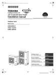
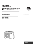
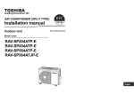
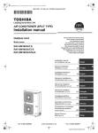
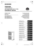
AIR CONDITIONER (SPLIT TYPE) Installation manual Outdoor Unit For commercial use Model name: RAV-SM1103AT-E1 RAV-SM1403AT-E1 English -1Original instruction ADOPTION OF NEW REFRIGERANT This Air Conditioner is a new type that has adopted a new refrigerant HFC (R410A) instead of the conventional refrigerant R22 in order to prevent destruction of the ozone layer. Equipment complying with IEC 61000-3-12. Thank you for purchasing this Toshiba air conditioner. Please read carefully through these instructions that contain important information which complies with the “Machinery” Directive (Directive 2006/42/EC), and ensure that you understand them. After reading these instructions, be sure to keep them in a safe place together with the Owner’s Manual and Installation Manual supplied with your product. Generic Denomination: Air Conditioner Definition of Qualified Installer or Qualified Service Person Contents 1 2 3 4 5 6 7 8 9 10 11 12 13 14 15 EN-1 PRECAUTIONS FOR SAFETY . . . . . . . . . . . . . . . . . . . . . . . . . . . . . . . . . 3 ACCESSORY PARTS AND REFRIGERANT . . . . . . . . . . . . . . . . . . . . . . 5 INSTALLATION OF NEW REFRIGERANT AIR CONDITIONER. . . . . . . 6 INSTALLATION CONDITIONS . . . . . . . . . . . . . . . . . . . . . . . . . . . . . . . . . 7 REFRIGERANT PIPING . . . . . . . . . . . . . . . . . . . . . . . . . . . . . . . . . . . . . . 9 AIR PURGING . . . . . . . . . . . . . . . . . . . . . . . . . . . . . . . . . . . . . . . . . . . . . 11 ELECTRICAL WORK . . . . . . . . . . . . . . . . . . . . . . . . . . . . . . . . . . . . . . . 12 EARTHING . . . . . . . . . . . . . . . . . . . . . . . . . . . . . . . . . . . . . . . . . . . . . . . 14 FINISHING. . . . . . . . . . . . . . . . . . . . . . . . . . . . . . . . . . . . . . . . . . . . . . . . 14 TEST RUN . . . . . . . . . . . . . . . . . . . . . . . . . . . . . . . . . . . . . . . . . . . . . . . . 14 ANNUAL MAINTENANCE . . . . . . . . . . . . . . . . . . . . . . . . . . . . . . . . . . . 14 FUNCTIONS TO BE IMPLEMENTED LOCALLY. . . . . . . . . . . . . . . . . . 15 TROUBLESHOOTING . . . . . . . . . . . . . . . . . . . . . . . . . . . . . . . . . . . . . . 18 APPENDIX. . . . . . . . . . . . . . . . . . . . . . . . . . . . . . . . . . . . . . . . . . . . . . . . 18 SPECIFICATIONS. . . . . . . . . . . . . . . . . . . . . . . . . . . . . . . . . . . . . . . . . . 20 The air conditioner must be installed, maintained, repaired and removed by a qualified installer or qualified service person. When any of these jobs is to be done, ask a qualified installer or qualified service person to do them for you. A qualified installer or qualified service person is an agent who has the qualifications and knowledge described in the table below. Agent Qualified installer Qualifications and knowledge which the agent must have • The qualified installer is a person who installs, maintains, relocates and removes the air conditioners made by Toshiba Carrier Corporation. He or she has been trained to install, maintain, relocate and remove the air conditioners made by Toshiba Carrier Corporation or, alternatively, he or she has been instructed in such operations by an individual or individuals who have been trained and is thus thoroughly acquainted with the knowledge related to these operations. • The qualified installer who is allowed to do the electrical work involved in installation, relocation and removal has the qualifications pertaining to this electrical work as stipulated by the local laws and regulations, and he or she is a person who has been trained in matters relating to electrical work on the air conditioners made by Toshiba Carrier Corporation or, alternatively, he or she has been instructed in such matters by an individual or individuals who have been trained and is thus thoroughly acquainted with the knowledge related to this work. • The qualified installer who is allowed to do the refrigerant handling and piping work involved in installation, relocation and removal has the qualifications pertaining to this refrigerant handling and piping work as stipulated by the local laws and regulations, and he or she is a person who has been trained in matters relating to refrigerant handling and piping work on the air conditioners made by Toshiba Carrier Corporation or, alternatively, he or she has been instructed in such matters by an individual or individuals who have been trained and is thus thoroughly acquainted with the knowledge related to this work. • The qualified installer who is allowed to work at heights has been trained in matters relating to working at heights with the air conditioners made by Toshiba Carrier Corporation or, alternatively, he or she has been instructed in such matters by an individual or individuals who have been trained and is thus thoroughly acquainted with the knowledge related to this work. EN-2 Qualified service person Definition of Protective Gear • The qualified service person is a person who installs, repairs, maintains, relocates and removes the air conditioners made by Toshiba Carrier Corporation. He or she has been trained to install, repair, maintain, relocate and remove the air conditioners made by Toshiba Carrier Corporation or, alternatively, he or she has been instructed in such operations by an individual or individuals who have been trained and is thus thoroughly acquainted with the knowledge related to these operations. • The qualified service person who is allowed to do the electrical work involved in installation, repair, relocation and removal has the qualifications pertaining to this electrical work as stipulated by the local laws and regulations, and he or she is a person who has been trained in matters relating to electrical work on the air conditioners made by Toshiba Carrier Corporation or, alternatively, he or she has been instructed in such matters by an individual or individuals who have been trained and is thus thoroughly acquainted with the knowledge related to this work. • The qualified service person who is allowed to do the refrigerant handling and piping work involved in installation, repair, relocation and removal has the qualifications pertaining to this refrigerant handling and piping work as stipulated by the local laws and regulations, and he or she is a person who has been trained in matters relating to refrigerant handling and piping work on the air conditioners made by Toshiba Carrier Corporation or, alternatively, he or she has been instructed in such matters by an individual or individuals who have been trained and is thus thoroughly acquainted with the knowledge related to this work. • The qualified service person who is allowed to work at heights has been trained in matters relating to working at heights with the air conditioners made by Toshiba Carrier Corporation or, alternatively, he or she has been instructed in such matters by an individual or individuals who have been trained and is thus thoroughly acquainted with the knowledge related to this work. When the air conditioner is to be transported, installed, maintained, repaired or removed, wear protective gloves and “safety” work clothing. In addition to such normal protective gear, wear the protective gear described below when undertaking the special work detailed in the table below. Failure to wear the proper protective gear is dangerous because you will be more susceptible to injury, burns, electric shocks and other injuries. Work undertaken Protective gear worn All types of work Protective gloves “Safety” working clothing Electrical-related work Gloves to provide protection for electricians and from heat Insulating shoes Clothing to provide protection from electric shock Work done at heights (50 cm or more) Helmets for use in industry Transportation of heavy objects Shoes with additional protective toe cap Repair of outdoor unit Gloves to provide protection for electricians and from heat Center of gravity (Unit: mm) Center of gravity Center of gravity EN-3 -2- EN-4 -3- 1 Warning Indications on the Air Conditioner Unit Warning indication PRECAUTIONS FOR SAFETY Description The manufacturer shall not assume any liability for the damage caused by not observing the description of this manual. WARNING ELECTRICAL SHOCK HAZARD Disconnect all remote electric power supplies before servicing. WARNING Moving parts. Do not operate unit with grille removed. Stop the unit before the servicing. CAUTION High temperature parts. You might get burned when removing this panel. CAUTION Do not touch the aluminum fins of the unit. Doing so may result in injury. CAUTION BURST HAZARD Open the service valves before the operation, otherwise there might be the burst. EN-5 WARNING ELECTRICAL SHOCK HAZARD Disconnect all remote electric power supplies before servicing. WARNING General WARNING Moving parts. Do not operate unit with grille removed. Stop the unit before the servicing. CAUTION High temperature parts. You might get burned when removing this panel. CAUTION Do not touch the aluminum fins of the unit. Doing so may result in injury. CAUTION BURST HAZARD Open the service valves before the operation, otherwise there might be the burst. • Before starting to install the air conditioner, read carefully through the Installation Manual, and follow its instructions to install the air conditioner. • Only a qualified installer(*1) or qualified service person(*1) is allowed to install the air conditioner. If the air conditioner is installed by an unqualified individual, a fire, electric shocks, injury, water leakage, noise and/or vibration may result. • Do not use any refrigerant different from the one specified for complement or replacement. Otherwise, abnormally high pressure may be generated in the refrigeration cycle, which may result in a failure or explosion of the product or an injury to your body. • When transporting the air conditioner, use a forklift and when moving the air conditioner by hand, move the unit with 4 people. • Before opening the intake grille of the indoor unit or service panel of the outdoor unit, set the circuit breaker to the OFF position. Failure to set the circuit breaker to the OFF position may result in electric shocks through contact with the interior parts. Only a qualified installer(*1) or qualified service person(*1) is allowed to remove the intake grille of the indoor unit or service panel of the outdoor unit and do the work required. • Before carrying out the installation, maintenance, repair or removal work, be sure to set the circuit breaker to the OFF position. Otherwise, electric shocks may result. • Place a “Work in progress” sign near the circuit breaker while the installation, maintenance, repair or removal work is being carried out. There is a danger of electric shocks if the circuit breaker is set to ON by mistake. • Only a qualified installer(*1) or qualified service person(*1) is allowed to undertake work at heights using a stand of 50 cm or more. • Wear protective gloves and safety work clothing during installation, servicing and removal. • Do not touch the aluminum fin of the outdoor unit. You may injure yourself if you do so. If the fin must be touched for some reason, first put on protective gloves and safety work clothing, and then proceed. • Do not climb onto or place objects on top of the outdoor unit. You may fall or the objects may fall off of the outdoor unit and result in injury. • When working at heights, use a ladder which complies with the ISO 14122 standard, and follow the procedure in the ladder’s instructions. Also wear a helmet for use in industry as protective gear to undertake the work. • When cleaning the filter or other parts of the outdoor unit, set the circuit breaker to OFF without fail, and place a “Work in progress” sign near the circuit breaker before proceeding with the work. • When working at heights, put a sign in place so that no-one will approach the work location, before proceeding with the work. Parts and other objects may fall from above, possibly injuring a person below. • The refrigerant used by this air conditioner is the R410A. • You shall ensure that the air conditioner is transported in stable condition. • Do not modify the products. Do not also disassemble or modify the parts. It may cause a fire, electric shock or injury. EN-6 Selection of installation location Electrical wiring • If you install the unit in a small room, take appropriate measures to prevent the refrigerant from exceeding the limit concentration even if it leaks. Consult the dealer from whom you purchased the air conditioner when you implement the measures. Accumulation of highly concentrated refrigerant may cause an oxygen deficiency accident. • Do not install the air conditioner in a location that may be subject to a risk of expire to a combustible gas. If a combustible gas leaks and becomes concentrated around the unit, a fire may occur. • When transporting the air conditioner, wear shoes with additional protective toe caps. • When transporting the air conditioner, do not take hold of the bands around the packing carton. You may injure yourself if the bands should break. • Do not place any combustion appliance in a place where it is directly exposed to the wind of air conditioner, otherwise it may cause imperfect combustion. • Only a qualified installer(*1) or qualified service person(*1) is allowed to carry out the electrical work of the air conditioner. Under no circumstances must this work be done by an unqualified individual since failure to carry out the work properly may result in electric shocks and/or electrical leaks. • The appliance shall be installed in accordance with national wiring regulations. Capacity shortages of the power circuit or an incomplete installation may cause an electric shock or fire. • Use wiring that meets the specifications in the Installation Manual and the stipulations in the local regulations and laws. Use of wiring which does not meet the specifications may give rise to electric shocks, electrical leakage, smoking and/or a fire. • Be sure to connect earth wire. (Grounding work) Incomplete grounding causes an electric shock. • Do not connect ground wires to gas pipes, water pipes, and lightning rods or ground wires for telephone wires. • After completing the repair or relocation work, check that the ground wires are connected properly. • Install a circuit breaker that meets the specifications in the installation manual and the stipulations in the local regulations and laws. • Install the circuit breaker where it can be easily accessed by the agent. • When installing the circuit breaker outdoors, install one which is designed to be used outdoors. • Under no circumstances must the power cable be extended. Connection trouble in the places where the cable is extended may give rise to smoking and/or a fire. Installation • Install the air conditioner at enough strong places to withstand the weight of the unit. If the strength is not enough, the unit may fall down resulting in injury. • Follow the instructions in the Installation Manual to install the air conditioner. Failure to follow these instructions may cause the product to fall down or topple over or give rise to noise, vibration, water leakage, etc. • The designated bolts (M10) and nuts (M10) for securing the outdoor unit must be used when installing the unit. • Install the outdoor unit property in a location that is durable enough to support the weight of the outdoor unit. Insufficient durability may cause the outdoor unit to fall, which may result in injury. • If refrigerant gas has leaked during the installation work, ventilate the room immediately. If the leaked refrigerant gas comes in contact with fire, noxious gas may be generated. Test run • Before operating the air conditioner after having completed the work, check that the electrical parts box cover of the indoor unit and service panel of the outdoor unit are closed, and set the circuit breaker to the ON position. You may receive an electric shock etc. if the power is turned on without first conducting these checks. • When you have noticed that some kind of trouble (such as when an error display has appeared, there is a smell of burning, abnormal sounds are heard, the air conditioner fails to cool or heat or water is leaking) has occurred in the air conditioner, do not touch the air conditioner yourself but set the circuit breaker to the OFF position, and contact a qualified service person. Take steps to ensure that the power will not be turned on (by marking “out of service” near the circuit breaker, for instance) until qualified service person arrives. Continuing to use the air conditioner in the trouble status may cause mechanical problems to escalate or result in electric shocks, etc. • After the work has finished, be sure to use an insulation tester set (500V Megger) to check the resistance is 1 Mȍ or more between the charge section and the non-charge metal section (Earth section). If the resistance value is low, a disaster such as a leak or electric shock is caused at user’s side. • Upon completion of the installation work, check for refrigerant leaks and check the insulation resistance and water drainage. Then conduct a test run to check that the air conditioner is operating properly. • After the installation work, confirm that refrigerant gas does not leak. If refrigerant gas leaks into the room and flows near a fire source, such as a cooking range, noxious gas may be generated. Refrigerant piping • Install the refrigerant pipe securely during the installation work before operating the air conditioner. If the compressor is operated with the valve open and without refrigerant pipe, the compressor sucks air and the refrigeration cycles is over pressurized, which may cause a injury. • Tighten the flare nut with a torque wrench in the specified manner. Excessive tighten of the flare nut may cause a crack in the flare nut after a long period, which may result in refrigerant leakage. • When the air conditioner has been installed or relocated, follow the instructions in the Installation Manual and purge the air completely so that no gases other than the refrigerant will be mixed in the refrigerating cycle. Failure to purge the air completely may cause the air conditioner to malfunction. • Nitrogen gas must be used for the airtight test. • The charge hose must be connected in such a way that it is not slack. EN-7 -4- EN-8 -5Explanations given to user • Upon completion of the installation work, tell the user where the circuit breaker is located. If the user does not know where the circuit breaker is, he or she will not be able to turn it off in the event that trouble has occurred in the air conditioner. • If you have discovered that the fan guard is damaged, do not approach the outdoor unit but set the circuit breaker to the OFF position, and contact a qualified service person(*1) to have the repairs done. Do not set the circuit breaker to the ON position until the repairs are completed. • After the installation work, follow the Owner’s Manual to explain to the customer how to use and maintain the unit. Relocation • Only a qualified installer(*1) or qualified service person(*1) is allowed to relocate the air conditioner. It is dangerous for the air conditioner to be relocated by an unqualified individual since a fire, electric shocks, injury, water leakage, noise and/or vibration may result. • When carrying out the pump-down work shut down the compressor before disconnecting the refrigerant pipe. Disconnecting the refrigerant pipe with the service valve left open and the compressor still operating will cause air, etc. to be sucked in, raising the pressure inside the refrigeration cycle to an abnormally high level, and possibly resulting in reputing, injury, etc. (*1) Refer to the “Definition of Qualified Installer or Qualified Service Person.” CAUTION New Refrigerant Air Conditioner Installation • THIS AIR CONDITIONER ADOPTS THE NEW HFC REFRIGERANT (R410A) WHICH DOES NOT DESTROY OZONE LAYER. R410A refrigerant is apt to be affected by impurities such as water, oxidizing membrane, and oils because the working pressure of R410A refrigerant is approx. 1.6 times as that of refrigerant R22. Accompanied with the adoption of the new refrigerant, the refrigeration machine oil has also been changed. Therefore, during installation work, be sure that water, dust, former refrigerant, or refrigeration machine oil does not enter the new type refrigerant R410A air conditioner circuit. To prevent mixing of refrigerant or refrigerating machine oil, the sizes of connecting sections of charging port on main unit and installation tools are different from those of the conventional refrigerant units. Accordingly, special tools are required for the new refrigerant (R410A) units. For connecting pipes, use new and clean piping materials with high pressure fittings made for R410A only, so that water and/or dust does not enter. 2 ACCESSORY PARTS AND REFRIGERANT Accessory Parts Part name Q’ty Shape Usage Hand this directly to the customer. (For other languages that do not appear in this Installation Manual, please refer to the enclosed CD-R.) Outdoor unit installation manual 1 CD-ROM 1 Drain nipple 1 Waterproof rubber cap 5 Protective bush 1 For protecting wires (pipe cover) Guard material for passage part 1 For protecting passage part (pipe cover) — Installation manual To Disconnect the Appliance from the Main Power Supply • This appliance must be connected to the main power supply by means of a switch with a contact separation of at least 3 mm. • A 25 A installation fuse (all fuse types can be used) must be used for the power supply line of this conditioner. EN-9 EN-10 3 INSTALLATION OF NEW REFRIGERANT AIR CONDITIONER Pipe cutter Cutting pipes R22 (Conventional tools) Welding machine and nitrogen cylinder Welding pipes R22 (Conventional tools) Refrigerant charging measure Charging refrigerant R22 (Conventional tools) • The R410A refrigerant is more susceptible to impurities such as water, oxide membranes, oils, and fats. With the adoption of the new refrigerant, the refrigerating oil has also been changed. Be careful not to let water, dust, conventional refrigerant, and/or conventional refrigerating oil enter the refrigerating cycle of the new refrigerant air conditioner. • To prevent different refrigerant or refrigerating oil from becoming mixed, the sizes of the charging port of the unit and the installation tool connection sections are different from those of the conventional refrigerant. Accordingly, the following exclusive tools are required for the new refrigerant R410A. Refrigerant Piping Required Tools/Equipment and Precautions for Use When using the conventional piping kit • When using the conventional piping kit with no indication of applicable refrigerant types, be sure to use it with a wall thickness of 0.8 mm for Ø9.5 mm and with a wall thickness of 1.0 mm for Ø15.9 mm. Do not use the conventional piping kit with a wall thickness less than these thicknesses due to insufficient pressure capacity. New refrigerant (R410A) Prepare the tools and equipment listed in the following table before starting the installation work. Newly prepared tools and equipment must be used exclusively. When using general copper pipes • Use general copper pipes with a wall thickness of 0.8 mm for Ø9.5 mm and with a wall thickness of 1.0 mm for Ø15.9 mm. Do not use any copper pipes with a wall thickness less than these thicknesses. Legend : Prepared newly (Use for R410A only. Do not use for refrigerant R22 or R407C etc.) : Conventional tools/equipment are available Tools/equipment Gauge manifold Charging hose Use Vacuuming/charging refrigerant and operation check How to use tools/equipment Prepared newly for R410A only Prepared newly for R410A only Unusable (Use the refrigerant charging measure instead.) Charging cylinder Can not be used Gas leak detector Gas leak check Vacuum pump Vacuum drying Vacuum pump with backflow prevention function Vacuum drying R22 (Conventional tools) Flare tool Flare machining of pipes Usable if dimensions are adjusted. Bender Bending pipes R22 (Conventional tools) Prepared newly Unusable Refrigerant recovery equipment Refrigerant recovery For R410A only Torque wrench Exclusive for Ø12.7 mm and Ø15.9 mm EN-11 Tightening flare nuts Flare nuts and flare machining • The flare nuts and flare machining are different from those for the conventional refrigerant. Use the flare nuts supplied with the air conditioner or those for R410A. • Before performing flare machining, carefully read “REFRIGERANT PIPING”. -6- EN-12 -7- 4 INSTALLATION CONDITIONS Installation Location 1. 2. CAUTION Before installation Air purge Be sure to prepare to the following items before installation. • To purge air, use a vacuum pump. • Do not use refrigerant charged in the outdoor unit to purge air. (The air purge refrigerant is not contained in the outdoor unit.) Length of refrigerant pipe Length of refrigerant pipe connected to indoor/outdoor unit 5 to 30 m *31 to 50 m Electrical wiring Item Addition of refrigerant is unnecessary at the local site. <Addition of refrigerant> Add 40 g of refrigerant for every 1 m of piping that exceeds 30 m. * Caution during addition of refrigerant When the total length of refrigerant piping exceeds 30 m, add 40 g/m of refrigerant up to a maximum total length of piping at 50 m. (Max. amount of additional refrigerant is 800 g.) Charge the refrigerant accurately. Overcharging may cause serious trouble with the compressor. • Do not connect a refrigerant pipe that is shorter than 5 m. This may cause a malfunction of the compressor or other devices. Airtight test 1. 2. 3. EN-13 Before starting an airtight test, further tighten the spindle valves on the gas and liquid sides. Pressurize the pipe with nitrogen gas charged from the service port to the design pressure (4.15 MPa) to conduct an airtight test. After the airtight test is completed, evacuate the nitrogen gas. • Be sure to fix the power wires and indoor/outdoor connecting wires with clamps so that they do not come into contact with the cabinet, etc. Earthing • Proper earthing can prevent charging of electricity on the outdoor unit surface due to the presence of a high frequency in the frequency converter (inverter) of the outdoor unit, as well as prevent electric shock. If the outdoor unit is not properly earthed, you may be exposed to an electric shock. Test Run Turn on the leakage breaker at least 12 hours before starting a test run to protect the compressor during startup. Install the outdoor unit in a location that meets the following conditions after the customer’s consent is obtained. • A well-ventilated location free from obstacles near the air inlets and air outlet • A location that is not exposed to rain or direct sunlight • A location that does not increase the operating noise or vibration of the outdoor unit • A location that does not produce any drainage problems from discharged water Do not install the outdoor unit in the following locations. • A location with a saline atmosphere (coastal area) or one that is full of sulfide gas (hot-spring area) (Special maintenance is required.) • A location subject to oil, vapor, oily smoke, or corrosive gases • A location in which organic solvent is used • Places where iron or other metal dust is present. If iron or other metal dust adheres to or collects on the interior of the air conditioner, it may spontaneously combust and start a fire. • A location where high-frequency equipment (including inverter equipment, private power generator, medical equipment, and communication equipment) is used (Installation in such a location may cause malfunction of the air conditioner, abnormal control or problems due to noise from such equipment.) • A location in which the discharged air of the outdoor unit blows against the window of a neighboring house • A location where the operating noise of the outdoor unit is transmitted • When the outdoor unit is installed in an elevated position, be sure to secure its feet. • A location in which drain water poses any problems. 3. Install the outdoor unit in a location where the discharge air is not blocked. When an outdoor unit is installed in a location that is always exposed to strong winds like a coast or on the high stories of a building, secure normal fan operation by using a duct or wind shield. When installing the outdoor unit in a location that is constantly exposed to strong winds such as on the upper stairs or rooftop of a building, apply the windproofing measures referred to in the following examples. 1) Install the unit so that its discharge port faces the wall of the building. Keep a distance 500 mm or more between the unit and wall surface. 500 mm 2) Consider the wind direction during the operational season of the air conditioner, and install the unit so that the discharge port is set at a right angle relative to the wind direction. Strong wind Strong wind EN-14 300 or more 300 or more 1,000 or more The height of the obstacle should be lower than the height of the outdoor unit. Obstacles in both front and rear of unit Open above and to the right and left of the unit. The height of an obstacle in both the front and rear of the unit, should be lower than the height of the outdoor unit. Suction 500 or more Obstacle also above unit 150 or more 200 or more 150 600 150 430 400 150 or more Knockout hole Drain nipple mounting hole 1,000 or more Obstacle in front Above unit is free 1. Single unit installation Serial installation of two or more units 200 or more 2. 500 or more 150 or more 2,000 or more Drain hole 300 or more EN-15 1,500 or more • Before installation, check the strength and horizontalness of the base so that abnormal sounds do not emanate. • According to the following base diagram, fix the base firmly with the anchor bolts. (Anchor bolt, nut: M10 x 4 pairs) Standard installation 1. Single unit installation Necessary Space for Installation (Unit: mm) Upper side is free 1. Single unit installation 1,000 or 300 or more more Installation of Outdoor Unit Fin Obstacle at rear side 1,000 or more Obstacle also at the above unit 40 Suction 300 or more Standard installation 365 Discharge Fin 150 or more Open above and to the right and left of the unit. The height of an obstacle in both the front and rear of the unit should be lower than the height of the outdoor unit. -8- 300 or more • As shown in the figure below, install the foundation and vibration-proof rubber pads to directly support the bottom surface of the fixing leg that is in contact with and underneath the bottom plate of the outdoor unit. * When installing the foundation for an outdoor unit with downward piping, consider the piping work. 1,000 or more Suction hood (Side) Discharge hood Suction hood (Rear side) 1,000 or more Serial installation of two or more units <Example> Serial installation in front and rear Serial installation of two or more units The height of the obstacle should be lower than the height of the outdoor unit. 300 or more 150 or more 3. 2. Obstacles on both right and left sides 200 or more 2. 200 or more • When using an air conditioner under low outside temperature conditions (Outside temp: -5 °C or lower) in COOL mode, prepare a duct or wind shield so that it is not affected by the wind. • When installing the unit in an area where snowfalls may be heavy, take steps to prevent the unit from being adversely affected by the fallen or accumulated snow. • Either make the foundation higher or install a stand (which is high enough to ensure that the unit will be above the fallen or accumulated snow) and place the unit on it. • Attach a snow shield (locally procured). EN-16 -9• GOOD When collectively draining discharged water completely, use a drain pan. Absorb vibration with vibration-proof rubber pads Fixing leg Foundation 5 REFRIGERANT PIPING Knockout of Pipe Cover Waterproof rubber cap Drain nipple Knockout procedure GOOD Knockout hole Bottom plate of outdoor unit Foundation Support the bottom surface of the fixing leg that is in contact with and underneath the bottom plate of the outdoor unit. If only the end of the fixing leg is supported, it may deform. Waterproof rubber cap Open Do not support the outdoor unit only with the fixing leg. Set the out margin of the anchor bolt to 15 mm or less. 15 or less When water is to be drained through the drain hose, attach the following drain nipple and waterproof rubber cap, and use the drain hose (Inner diam: 16 mm) sold on the market. Also seal knockout hole and the screws securely with silicone material, etc., to prevent water from leaking. Some conditions may cause dewing or dripping of water. Pipe cover Front direction If a heating operation is to be continuously performed for a long time under the condition that the outdoor temperature is 0 °C or lower, draining defrosted water may be difficult due to the bottom plate freezing, resulting in trouble with the cabinet or fan. It is recommended to procure an anti-freeze heater locally in order to safely install the air conditioner. For details, contact the dealer. 1. Remove the screws from the front panel. 2. Pull the front panel downward. Removing the front panel, the electric parts are located in front. • The metal pipes are attachable to the piping holes. If the size of the conduit pipe being used does not match the hole, adjust the hole size to match the pipe size. Electric parts box Service panel Side direction Drain nipple For Reference NO GOOD Foundation • Rear direction How to remove the front panel Down direction • The indoor/outdoor connecting pipes can be connected in 4 directions. Take off the knockout part of the pipe cover through which pipes or wires will pass through the base plate. • Detach the pipe cover and tap on the knockout section a few times with the shank of a screwdriver. A knockout hole can easily be punched. • After punching out the knockout hole, remove burrs from the hole and then install the supplied protective bush and guard material around the passage hole to protect wires and pipes. Be sure to attach the pipe covers after pipes have been connected. Cut the slits under the pipe covers to facilitate the installation. After connecting the pipes, be sure to mount the pipe cover. The pipe cover is easily mounted by cutting off the slit at the lower part of the pipe cover. * Be sure to wear heavy work gloves while working. EN-17 EN-18 Optional Installation Parts (Locally procured) Flaring Tightening of Connecting Part 1. 1. 2. Parts name Q’ty A Refrigerant piping Liquid side: Ø9.5 mm Gas side: Ø15.9 mm B Pipe insulating material (polyethylene foam, 10 mm thick) C Putty, PVC tape One each 1 One each Cut the pipe with a pipe cutter. Be sure to remove burrs that may cause a gas leak. Insert a flare nut into the pipe, and then flare the pipe. Use the flare nuts supplied with the air conditioner or those for R410A. Insert a flare nut into the pipe, and flare the pipe. As the flaring sizes of R410A differ from those of refrigerant R22, the flare tools newly manufactured for R410A are recommended. However, the conventional tools can be used by adjusting the projection margin of the copper pipe. Align the centers of the connecting pipes and fully tighten the flare nut with your fingers. Then fix the nut with a wrench as shown in the figure and tighten it with a torque wrench. Half union or packed valve Externally threaded side Internally threaded side Tighten with torque wrench. Projection margin in flaring: B (Unit: mm) Cap 2. CAUTION Rigid (Clutch type) Outer diam. of copper pipe 9.5 R410A tool used 15.9 Conventional tool used As shown in the figure, be sure to use two wrenches to loosen or tighten the flare nut of the valve on the gas side. If you use a single crescent, the flare nut cannot be tightened to the required tightening torque. On the other hand, use a single crescent to loosen or tighten the flare nut of the valve on the liquid side. (Unit: N•m) R410A 0 to 0.5 1.0 to 1.5 Outer dia. of copper pipe Tightening torque 9.5 mm (diam.) 33 to 42 (3.3 to 4.2 kgf•m) 15.9 mm (diam.) 63 to 77 (6.3 to 7.7 kgf•m) Flaring diameter size: A (Unit: mm) Piping connection A Cover Liquid side Outer diameter Thickness Ø9.5 mm 0.8 mm Gas side Outer diameter Thickness Ø15.9 mm 1.0 mm • After the installation work, be sure to check for gas leaks of the pipe connections with nitrogen. • Pressure of R410A is higher than that of R22 (Approx. 1.6 times). Therefore, using a torque wrench, tighten the flare pipe connecting sections that connect the indoor/ outdoor units at the specified tightening torque. Incomplete connections may cause not only a gas leak, but also trouble with the refrigeration cycle. Do not apply refrigerating machine oil to the flared surface. Cap Outer dia. of copper pipe +0 A –0.4 9.5 13.2 15.9 19.7 Piping valve Loosened Tightened Flare nut * In case of flaring for R410A with the conventional flare tool, pull the tool out approx. 0.5 mm more than that for R22 to adjust it to the specified flare size. The copper pipe gauge is useful for adjusting the projection margin size. EN-19 2. Do not put the crescent wrench on the cap or cover. The valve may break. If applying excessive torque, the nut may break according to some installation conditions. Cover B TAKE NOTE OF THESE 4 IMPORTANT POINTS BELOW FOR PIPING WORK 1. Keep dust and moisture away from inside the connecting pipes. 2. Tightly connect the connection between pipes and the unit. 3. Evacuate the air in the connecting pipes using a VACUUM PUMP. 4. Check for gas leaks at connection points. 1. NO GOOD Fix with wrench. Refrigerant Piping Connection Flare nut CAUTION Valve at gas side - 10 - EN-20 - 11 - 6 Refrigerant Pipe Length AIR PURGING Single Allowable pipe length (m) Airtight test Height difference (Indoor-outdoor H) (m) Total length L Indoor unit: Upper Outdoor unit: Lower 50 30 30 Pipe diameter (mm) Number of bent portions Gas side Liquid side Ø15.9 Ø9.5 10 or less Vacuum pump Before starting an airtight test, further tighten the spindle valves on the gas side and liquid side. Pressurize the pipe with nitrogen gas charged from the service port to the design pressure (4.15 MPa) to conduct the airtight test. After the airtight test is completed, evacuate the nitrogen gas. Allowable pipe length (m) System TWIN Total length • 1+ 2 • 1+ 3 • 1+ 4 Maximum Model Distributed pipes • 2 • 3 • 4 Maximum Height difference (m) Distributed pipes • 3– 2 • 4– 2 • 4– 3 Maximum Indoor-outdoor H Indoor unit: Upper Outdoor unit: Upper Indoorindoor (∆h) SM110 50 15 10 30 30 0.5 SM140 50 15 10 30 30 0.5 Pipe diameter (mm) System TWIN Main pipe Model Number of bent portions Branching pipe Gas side Liquid side Gas side Liquid side SM110 Ø15.9 Ø9.5 Ø12.7 Ø6.4 10 or less SM140 Ø15.9 Ø9.5 Ø15.9 Ø9.5 10 or less Figure of Single Figure of Simultaneous twin Indoor Unit Compound pressure gauge Charge hose (For R410A only) Indoor Unit Indoor Unit 3 2 1 H L H Outdoor Unit Pressure gauge Gauge manifold valve Handle High (Keep fully closed) Charge hose (For R410A only) Vacuum pump adapter for counterflow prevention (For R410A only) Vacuum pump Distributor Outdoor Unit Open Handle Low fully. With respect to the preservation of the terrestrial environment, adopt “Vacuum pump” to purge air (Evacuate air in the connecting pipes) when installing the unit. • Do not discharge the refrigerant gas to the atmosphere to preserve the terrestrial environment. • Use a vacuum pump to discharge the air (nitrogen, etc.) that remains in the set. If air remains, the capacity may decrease. For the vacuum pump, be sure to use one with a backflow preventer so that the oil in the pump does not backflow into the pipe of the air conditioner when the pump stops. (If oil in the vacuum pump is put in an air conditioner including R410A, it may cause trouble with the refrigeration cycle.) –101 kPa (–76 cmHg) Handle Low Charge port (Valve core (Setting pin)) L Attach the connecting port of the charge hose with a projection to push the valve core (setting pin) to the charge port of the set. L Air Purge Simultaneous twin As shown in the figure, connect the charge hose after the manifold valve is closed completely. L Turn ON the vacuum pump. (*1) L Loosen the flare nut of the packed valve (Gas side) a little to check that the air passes through. (*2) L Retighten the flare nut. L Execute vacuuming until the compound pressure gauge indicates –101 kPa (–76 cmHg). (*1) L Close Handle Low completely. L Turn OFF the vacuum pump. L Leave the vacuum pump as it is for 1 or 2 minutes, and check that the indicator of the compound pressure gauge does not return. L Open the valve stem or valve handle fully. (First, at liquid side, then gas side) L Disconnect the charge hose from the charge port. Packed valve at gas side L Tighten the valve and caps of the charge port securely. EN-21 EN-22 *1 *2 Use the vacuum pump, vacuum pump adapter, and gauge manifold correctly referring to the manuals supplied with each tool before using them. Check that the vacuum pump oil is filled up to the specified line of the oil gauge. When air is not charged, check again whether the connecting port of the discharge hose, which has a projection to push the valve core, is firmly connected to the charge port. How to open the valve Valve handling precautions • Open the valve stem until it strikes the stopper. It is unnecessary to apply further force. • Securely tighten the cap with a torque wrench. ELECTRICAL WORK Cap tightening torque Ø9.5 mm 33 to 42 N•m (3.3 to 4.2 kgf•m) Ø15.9 mm 20 to 25 N•m (2.0 to 2.5 kgf•m) Valve size Open or close the valve. Liquid side Open the valve with a 4 mm hexagon wrench. 7 1. 14 to 18 N•m (1.4 to 1.8 kgf•m) Charge port 2. Gas side Valve unit Using a minus screwdriver, turn it counterclockwise by 90° until it hits the stopper. (Full open) Charge port Replenishing refrigerant This model is a 30 m chargeless type that does not need to have its refrigerant replenished for refrigerant pipes up to 30 m. When a refrigerant pipe longer than 30 m is used, add the specified amount of refrigerant. Refrigerant replenishing procedure 1. 2. Flare nut Handle position Closed completely Opened fully Stopper pin 3. After vacuuming the refrigerant pipe, close the valves and then charge the refrigerant while the air conditioner is not working. When the refrigerant cannot be charged to the specified amount, charge the required amount of refrigerant from the charge port of the valve on the gas side during cooling. Movable part of valve (Stem) NOTE Using the specified wires, ensure that the wires are connected, and fix wires securely so that the external tension to the wires does not affect the connecting part of the terminals. Incomplete connection or fixation may cause a fire, etc. Be sure to connect the earth wire. (grounding work) Incomplete grounding may lead to electric shock. Do not connect ground wires to gas pipes, water pipes, lightning rods or ground wires for telephone wires. The appliance shall be installed in accordance with national wiring regulations. Capacity shortages of the power circuit or an incomplete installation may cause an electric shock or fire. • Remove the panel, and you can see electric parts on the front side. • A metal pipe can be installed through the hole for wiring. If the hole size does not fit the wiring pipe to be used, drill the hole again to an appropriate size. • Be sure to clamp the power wires and indoor/outdoor connecting wires with a banding band along the connecting pipe so that the wires do not touch the compressor or discharge pipe. (The compressor and the discharge pipe become hot.) Furthermore, be sure to secure these wires with the cord clamps on the valve fixing plate. CAUTION • Wrong wiring may cause a burn-out of some electrical parts. • Be sure to use the cord clamps attached to the product. • Do not damage or scratch the conductive core or inner insulator of the power and inter-connecting wires when peeling them. • Use the power and Inter-connecting wires with specified thicknesses, specified types and protective devices required. Requirement for replenishing refrigerant Replenish liquid refrigerant. When gaseous refrigerant is replenished, the refrigerant composition varies, which disables normal operation. Adding additional refrigerant Main stopper WARNING 31~50 m: L 40 g × (L-30) • While the valve is fully opened, after the screwdriver has reached the stopper, do not apply torque exceeding 5 N•m. Applying excessive torque may damage the valve. EN-23 • L: Pipe length • To add additional refrigerant to twin system, refer to the installation manual supplied with the branching pipe (sold separately). • The refrigerant need not be reduced for a 30 meter (or less) refrigerant pipe. - 12 - EN-24 - 13 Wiring between Indoor Unit and Outdoor Unit How to wire The dashed lines show on-site wiring. 1. 2. 3. Outdoor unit Input power L N 1 2 3 Indoor unit 1 2 3 Wired remote controller Α Β Circuit breaker • Connect the indoor/outdoor connecting wires to the identical terminal numbers on the terminal block of each unit. Incorrect connection may cause a failure. For the air conditioner, connect a power wire with the following specifications. Model (RAV- Type) SM110 Power supply Maximum running current Recommended field fuse SM140 220-240 V~ 50 Hz 22.0 A 22.8 A 25 A Power wire* 3 × 2.5 mm2 or more (H07 RN-F or 60245 IEC 66) Indoor/outdoor connecting wires* 4 × 1.5 mm2 or more (H07 RN-F or 60245 IEC 66) * Number of wire × wire size EN-25 Remove the front panel (two screws). Detach the terminal cover (two screws). Connect the connecting wire to the terminal as identified with their respective numbers on the terminal block of the indoor and outdoor units. H07 RN-F or 60245 IEC 66 (1.5 mm 2 or more) • When connecting the connecting wire to the outdoor unit terminal, prevent water from coming into the outdoor unit. • Insulate the unsheathed cords (conductors) with electrical insulation tape. Process them so that they do not touch any electrical or metal parts. • For interconnecting wires, do not use a wire joined to another on the way. Use wires long enough to cover the entire length. Screw Terminal cover Cord clamp CAUTION Wiring connections differ in conformance to EMC standards, depending whether the system is single or twin. Connect wires according to respective instructions. • An installation fuse must be used for the power supply line of this air conditioner. • Incorrect/incomplete wiring may lead to an electrical fire or smoke. • Prepare an exclusive power supply for the air conditioner. • This product can be connected to the mains power. Fixed wire connections: A switch that disconnects all poles and has a contact separation of at least 3 mm must be incorporated in the fixed wiring. EN-26 Wiring diagram * For details on the remote controller wiring/installation, refer to the Installation Manual enclosed with the remote controller. Indoor/outdoor connecting wire Earth screw Single system 1 2 Power supply wire Earth screw 3 L 8 Connect the earth line properly following applicable technical standards. Connecting the earth line is essential to preventing electric shock and to reducing noise and electrical charges on the outdoor unit surface due to the high-frequency wave generated by the frequency converter (inverter) in the outdoor unit. If you touch the charged outdoor unit without an earth line, you may experience an electric shock. N Remote controller Remote controller wiring Indoor side A B 1 2 3 1 2 3 L N 9 Indoor/Outdoor connecting wires Outdoor side Cord clamp Cord clamp Simultaneous twin system Remote controller wiring Indoor side Indoor/Outdoor connecting wires Outdoor side Stripping length power cord and connecting wire Remote controller inter-unit wiring 10 B 1 2 3 1 2 3 L N Power supply Indoor side A B 1 2 3 Indoor power inter-unit wiring * Use 2-core shield wire (MVVS 0.5 to 2.0 mm² or more) for the remote controller wiring in the simultaneous twin system to prevent noise problems. Be sure to connect both ends of the shield wire to earth leads. * Connect earth wires for each indoor unit in the simultaneous twin system. Earth line 10 TEST RUN L N 10 10 10 50 A 1 2 3 FINISHING After the refrigerant pipe, inter-unit wires, and drain pipe have been connected, cover them with finishing tape and clamp them to the wall with off-the-shelf support brackets or their equivalent. Keep the power wires and indoor/outdoor connecting wires off the valve on the gas side or pipes that have no heat insulator. Power supply Remote controller EARTHING 40 50 Earth line Connecting wire • Turn on the leakage breaker at least 12 hours before starting a test run to protect the compressor during startup. To protect the compressor, power is supplied from the 220-240 VAC input to the unit to preheat the compressor. • Check the following before starting a test run: • That all pipes are connected securely without leaks. • That the valve is open. If the compressor is operated with the valve closed, the outdoor unit will become overpressurized, which may damage the compressor or other components. If there is a leak at a connection, air can be sucked in and the internal pressure further increases, which may cause a burst or injury. • Operate the air conditioner in the correct procedure as specified in the Owner’s Manual. 40 (mm) Power supply wire 11 ANNUAL MAINTENANCE • For an air conditioning system that is operated on a regular basis, cleaning and maintenance of the indoor/outdoor units are strongly recommended. As a general rule, if an indoor unit is operated for about 8 hours daily, the indoor/outdoor units will need to be cleaned at least once every 3 months. This cleaning and maintenance should be carried out by a qualified service person. Failure to clean the indoor/outdoor units regularly will result in poor performance, icing, water leaking and even compressor failure. EN-27 - 14 - EN-28 - 15 - 12 FUNCTIONS TO BE IMPLEMENTED LOCALLY Handling Existing Pipe When using the existing pipe, carefully check for the following: • Wall thickness (within the specified range) • Scratches and dents • Water, oil, dirt, or dust in the pipe • Flare looseness and leakage from welds • Deterioration of copper pipe and heat insulator Refrigerant Recovery When recovering the refrigerant in situations such as when relocating an indoor unit or outdoor unit, the recovery operation can be performed by operating the SW800 and SW801 switches on the P.C. board of the outdoor unit. A cover for the electric parts has been installed in order to provide protection from electric shocks while work is being performed. Operate the service switches and check the LED displays with this electric parts cover in place. Do not remove this cover while the power is still on. DANGER The entire P.C. board of this air conditioner system is a high-voltage area. When operating the service switches with the power of the system left on, wear electrically insulated gloves. Cautions for using existing pipe • Do not reuse a flare nut to prevent gas leaks. Replace it with the supplied flare nut and then process it to a flare. • Blow nitrogen gas or use an appropriate means to keep the inside of the pipe clean. If discolored oil or much residue is discharged, wash the pipe. • Check welds, if any, on the pipe for gas leaks. When the pipe corresponds to any of the following, do not use it. Install a new pipe instead. • The pipe has been opened (disconnected from indoor unit or outdoor unit) for a long period. • The pipe has been connected to an outdoor unit that does not use refrigerant R22, R410A or R407C. • The existing pipe must have a wall thickness equal to or larger than the following thicknesses. Reference outside diameter (mm) Wall thickness (mm) Ø9.5 0.8 Ø15.9 1.0 Ø19.0 1.0 • Do not use any pipe with a wall thickness less than these thicknesses due to insufficient pressure capacity. Service switches SW800, SW801 Electric parts cover Inspection window through which to check the LED displays D800 D801 D802 D803 D804 D805 (yellow) (yellow) (yellow) (yellow) (yellow) (green) • In the initial LED display status, D805 is lighted as shown on the right. If the initial status is not established (if D805 is flashing), hold down the SW800 and SW801 service switches simultaneously for at least 5 seconds to return the LED displays to the initial status. • There are four LEDs display patterns. : ON : OFF : Rapid flashing (5 times/sec.) : Slow flashing (1 time/sec.) LED display initial status D800 or (Yellow) OFF or rapid flashing D801 or (Yellow) OFF or rapid flashing D802 or (Yellow) OFF or rapid flashing D803 or (Yellow) OFF or rapid flashing D804 or D805 EN-29 (Yellow) OFF or rapid flashing (Green) ON EN-30 Steps taken to recover the refrigerant Existing piping 1. 2. 3. 4. The following settings are required when using a pipe Ø19.1 mm as the existing piping at the gas pipe side. Operate the indoor unit in the fan mode. Check that the LED displays are placed in their initial status. If not, place them in the initial status. Hold down SW800 for at least 5 seconds, and check that D804 flashes slowly. (Fig. 1) Press SW800 once to set the LED displays (D800 to D805) to the “refrigerant recovery LED display” shown below. (Fig. 2) LED displays indicated when step 3 is taken 6. 1. 2. 3. 4. Refrigerant recovery LED display Set the circuit breaker to the ON position to turn on the power. Check that the LED displays are placed in their initial status. If not, place them in the initial status. Hold down SW800 for at least 5 seconds, and check that D804 flashes slowly. (Fig. 5) Press SW800 four times to set the LED displays (D800 to D805) to the “LED displays for existing piping settings” shown below. (Fig. 6) D800 D800 D801 D801 D802 D802 D803 D803 D800 D800 D804 D804 D801 D801 D805 D805 D802 D802 D803 D803 D804 D804 : ON, 5. Steps taken to support existing piping : OFF, : slow flashing (Fig. 1) : ON, LED displays indicated when step 3 is taken : OFF, : rapid flashing (Fig. 2) D805 Press SW801 to set D805 to rapid flashing. (Each time SW801 is pressed, D805 is switched between rapid flashing and OFF.) (Fig. 3) Hold down SW801 for at least 5 seconds, and when D804 flashes slowly and D805 lights, the forced cooling operation is started. (Max. 10 minutes) (Fig. 4) : ON, 5. LED displays indicated when step 5 is taken LED displays indicated when step 6 is taken D800 D800 D801 D801 D802 D802 D803 D803 D804 D804 D805 D805 : ON, : OFF, : rapid flashing (Fig. 3) : ON, 6. D805 : OFF, : slow flashing (Fig. 5) After operating the system for at least 3 minutes, close the valve on the liquid side. After the refrigerant has been recovered, close the valve on the gas side. Hold down SW800 and SW801 simultaneously for at least 5 seconds. The LED displays are returned to the initial status, and the cooling operation and indoor fan operation stop. 10. Turn off the power. * If there is any reason to doubt whether the recovery was successful in the course of this operation, hold down SW800 and SW801 simultaneously for at least 5 seconds to return to the initial status, and then repeat the steps for recovering the refrigerant. EN-31 : OFF, : rapid flashing (Fig. 6) LED displays indicated when step 6 is taken D800 D800 D801 D801 D802 D802 D803 D803 D804 D804 D805 7. 8. 9. : ON, Press SW801 to set D805 to rapid flashing. (Each time SW801 is pressed, D805 is switched between rapid flashing and OFF.) (Fig. 7) Hold down SW801 for at least 5 seconds, and check that D804 flashes slowly and that D805 lights. (Fig. 8) LED displays indicated when step 5 is taken : OFF, : slow flashing (Fig. 4) LED displays for existing piping settings : ON, D805 : OFF, : rapid flashing (Fig. 7) : ON, : OFF, : slow flashing (Fig. 8) 7. Hold down SW800 and SW801 simultaneously for at least 5 seconds to return the LED displays to the initial status. The existing piping is now supported by taking the above steps. In this status, the heating capacity may decrease during heating depending on the outside air temperature and indoor temperature. * If there is any reason to doubt whether establishing support was successful in the course of this operation, hold down SW800 and SW801 simultaneously for at least 5 seconds to return to the initial status, and then repeat the setting steps. - 16 - EN-32 - 17 How to check the existing piping settings You can check whether the existing piping settings are enabled. 1. Check that the LED displays are placed in their initial status. If not, place them in the initial status. 2. Hold down SW800 for at least 5 seconds, and check that D804 flashes slowly. (Fig. 9) 3. Press SW800 four times to set the LED displays (D800 to D805) to the “LED displays for existing piping settings” shown below. If the setting is enabled, D802 lights and D804 and D805 flash rapidly. (Fig. 10) 4. Hold down SW800 and SW801 simultaneously for at least 5 seconds to return the LED displays to the initial status. 4. 5. Hold down SW801 for at least 5 seconds, and check that D804 flashes slowly. (Fig. 13) Hold down SW800 and SW801 simultaneously for at least 5 seconds to return the LED displays to the initial status. LED displays indicated when step 4 is taken D800 D801 D802 LED displays indicated when step 3 is taken LED displays for existing piping settings D803 D800 D800 D804 D801 D801 D805 D802 D802 D803 D803 D804 D804 D805 D805 : ON, : OFF, : slow flashing (Fig. 9) : ON, : ON, : OFF, : slow flashing (Fig. 13) : OFF, : rapid flashing (Fig. 10) When restoring the factory settings To restore the factory settings in situations such as when relocating the units, follow the steps below. 1. Check that the LED displays are placed in their initial status. If not, place them in the initial status. 2. Hold down SW800 for at least 5 seconds, and check that D804 flashes slowly. (Fig. 11) 3. Press SW800 14 times to set the LED displays (D800 to D805) to the “LED displays restored to factory settings” shown below. (Fig. 12) LED displays indicated when step 2 is taken D800 D801 D801 D802 D802 D803 D803 D804 D804 D805 : ON, EN-33 LED displays restored to factory settings D800 D805 : OFF, : slow flashing (Fig. 11) : ON, : OFF, : rapid flashing (Fig. 12) EN-34 13 TROUBLESHOOTING 14 APPENDIX Work instructions You can perform fault diagnosis of the outdoor unit with the LEDs on the P.C. board of the outdoor unit in addition to using the check codes displayed on the wired remote controller of the indoor unit. Use the LEDs and check codes for various checks. Details of the check codes displayed on the wired remote controller of the indoor unit are described in the Installation Manual of the indoor unit. The existing R22 and R407C piping can be reused for our digital inverter R410A product installations. WARNING 1 2 3 4 5 6 7 8 9 10 11 12 13 14 15 16 17 18 19 20 21 22 23 : ON, Display D800 D801 D802 D803 D804 D805 Error * The LEDs and switches are located at the top right of the P.C. board of the outdoor unit as shown in the figure on the right. Thickness 3. 4. Basic conditions needed to reuse existing pipes Check and observe the presence of three conditions in the refrigerant piping works. 1. Dry (There is no moisture inside of the pipes.) 2. Clean (There is no dust inside of the pipes.) 3. Tight (There are no refrigerant leaks.) 5. 6. Restrictions for use of existing pipes In the following cases, the existing pipes should not be reused as they are. Clean the existing pipes or exchange them with new pipes. 1. When a scratch or dent is heavy, be sure to use new pipes for the refrigerant piping works. 2. When the existing pipe thickness is thinner than the specified “Pipe diameter and thickness,” be sure to use new pipes for the refrigerant piping works. • The operating pressure of R410A is high (1.6 times that of R22 and R407C). If there is a scratch or dent on the pipe or a thinner pipe is used, the pressure strength may be inadequate, which may cause the pipe to break in the worst case. : rapid flashing (5 times/sec.) Service switches SW800, SW801 EN-35 Confirming the existence of scratches or dents on the existing pipes and confirming the reliability of the pipe strength are conventionally referred to the local site. If the specified conditions can be cleared, it is possible to update existing R22 and R407C pipes to those for R410A models. Normal Discharge temperature sensor (TD) error Heat exchanger temperature sensor (TE) error Heat exchanger temperature sensor (TL) error Outside air temperature sensor (TO) error Suction temperature sensor (TS) error Heat sink temperature sensor (TH) error Heat exchanger sensor (TE, TS) connection error EEPROM error Compressor breakdown Compressor lock Model data not set Discharge temperature error Power supply error High pressure SW error Heat sink overheating error Gas leak detected 4-way valve reverse error High pressure release operation Fan system error Drive device short-circuiting Position detection circuit error Compressor IPDU or other (not specifically identified) : OFF, Pipe outer diameter Ø6.4 Ø9.5 Ø12.7 Ø15.9 Ø19.0 R410A LED displays and check codes No. * Pipe diameter and thickness (mm) Electric parts cover (yellow) D800 (yellow) D801 (yellow) D802 (yellow) D803 (yellow) D804 (green) D805 Inspection window through which to check the LED displays - 18 - 7. R22 (R407C) 0.8 0.8 0.8 1.0 1.0 • In case the pipe diameter is Ø12.7 mm or less and the thickness is less than 0.7 mm, be sure to use new pipes for the refrigerant piping works. When the outdoor unit was left with the pipes disconnected, or the gas leaked from the pipes and the pipes were not repaired and refilled. • There is the possibility of rain water or air, including moisture, entering the pipe. When refrigerant cannot be recovered using a refrigerant recovery unit. • There is the possibility that a large quantity of dirty oil or moisture remains inside the pipes. When a commercially available dryer is attached to the existing pipes. • There is the possibility that copper green rust has been generated. When the existing air conditioner is removed after refrigerant has been recovered. Check if the oil is judged to be clearly different from normal oil. • The refrigerator oil is copper rust green in color: There is the possibility that moisture has mixed with the oil and rust has been generated inside the pipe. • There is discolored oil, a large quantity of residue, or a bad smell. • A large quantity of shiny metal dust or other wear residue can be seen in the refrigerant oil. When the air conditioner has a history of the compressor failing and being replaced. • When discolored oil, a large quantity of residue, shiny metal dust, or other wear residue or mixture of foreign matter is observed, trouble will occur. EN-36 - 19 8. 9. When temporary installation and removal of the air conditioner are repeated such as when leased etc. If the type of refrigerator oil of the existing air conditioner is other than the following oil (Mineral oil), Suniso, Freol-S, MS (Synthetic oil), alkyl benzene (HAB, Barrel-freeze), ester series, PVE only of ether series. • The winding-insulation of the compressor may deteriorate. NOTE The above descriptions are results have been confirmed by our company and represent our views on our air conditioners, but do not guarantee the use of the existing pipes of air conditioners that have adopted R410A in other companies. Branching pipe for simultaneous operation system • In the concurrent twin system, when TOSHIBA has specified that branching pipe is to be used, it can be reused. Branching pipe model name: RBC-TWP30E2, RBC-TWP50E2 On the existing air conditioner for simultaneous operation system (twin, triple system), there are cases of branch pipes being used that have insufficient compressive strength. In such case, please change the piping to a branch pipe for R410A. Curing of pipes When removing and opening the indoor or outdoor unit for a long time, cure the pipes as follows: • Otherwise rust may be generated when moisture or foreign matter due to condensation enters the pipes. • The rust cannot be removed by cleaning, and new pipes are necessary. Placement location Outdoors Indoors Term Curing manner 1 month or more Pinching Less than 1 month Every time Pinching or taping Are there scratches or dents on the existing pipes? YES Existing pipes: Cannot be used. • Use new pipes. NO Is it possible to operate the existing air conditioner? NO YES • After the existing air conditioner is operated in cooling mode for approx. 30 minutes or longer,* recover the refrigerant. • For cleaning the pipes and recovering oil • Refrigerant recovery: Pump down method Nitrogen gas pressure 0.5 MPa • Remove the existing air conditioner from the piping and carry out flushing (nitrogen pressure 0.5 MPa) to remove any remains inside of the pipe. Note] In case of twin pipes, also be sure to flush the branching pipe. (If there is discharge of remains, it is judged that a large quantity of remains are present.) Was largely discolored oil or a large quantity of remains discharged? (When the oil deteriorates, the color of the oil changes to a muddy or black color.) YES Clean the pipes or use new pipes. NO Connect the indoor/outdoor units to the existing pipe. • Use a flare nut attached to the main unit for the indoor/outdoor units. (Do not use the flare nut of the existing pipe.) • Re-machine the flare machining size to size for R410A. Piping necessary to change the flare nut/ machining size due to pipe compression In case that a gas pipe Ø19 mm or bigger is used for the outdoor unit of SM80 (3 HP): (Our R410A model 3 to 6 HP gas pipe size is Ø15.9 mm) 1) Flare nut width: H Copper pipe outer diameter See page 16. H For R410A For R22 • (Airtight test), Vacuum dry, Refrigerant charge, Gas leak check (mm) Ø6.4 Ø9.5 17 22 Same as above Ø12.7 Ø15.9 Ø19.0 26 29 36 24 27 Same as above 2) Flare machining size: A (mm) A Test run Copper pipe outer diameter Ø6.4 Ø9.5 Ø12.7 Ø15.9 For R410A 9.1 13.2 16.6 19.7 24.0 For R22 9.0 13.0 16.2 19.4 23.3 Ø19.0 Becomes a little larger for R410A Do not apply refrigerator oil to the flare surface. EN-37 EN-38 15 SPECIFICATIONS Model Declaration of Conformity Sound power level (dB) Manufacturer: Toshiba Carrier Corporation 336 Tadehara, Fuji-shi, Shizuoka-ken 416-8521 JAPAN Authorized Representative/ TCF holder: Nick Ball Toshiba EMEA Engineering Director Toshiba Carrier UK Ltd. Porsham Close, Belliver Industrial Estate, PLYMOUTH, Devon, PL6 7DB. United Kingdom Weight (kg) Cooling Heating RAV-SM1103AT-E1 70 71 76 RAV-SM1403AT-E1 71 71 76 Hereby declares that the machinery described below: Generic Denomination: Air Conditioner Model/type: RAV-SM1103AT-E1 RAV-SM1403AT-E1 Commercial name: Digital Inverter Series Air Conditioner Complies with the provisions of the “Machinery” Directive (Directive 2006/42/EC) and the regulations transposing into national law Complies with the provisions of the following harmonized standard: EN 378-2: 2008+A1:2009 Note: EN-39 - 20 - This declaration becomes invalid if technical or operational modifications are introduced without the manufacturer’s consent. EN-40 - 21 - This product contains fluorinated greenhouse gases covered by the Kyoto Protocol Chemical Name of Gas Global Warming Potential (GWP) of Gas R410A 1 975 CAUTION 1. 2. 3. 4. 5. 6. 7. Paste the enclosed refrigerant label adjacent to the charging and/or recovering location. Clearly write the charged refrigerant quantity on the refrigerant label using indelible ink. Then, place the included transparent protective sheet over the label to prevent the writing from rubbing off. Prevent emission of the contained fluorinated greenhouse gas. Ensure that the fluorinated greenhouse gas is never vented to the atmosphere during installation, service or disposal. When any leakage of the contained fluorinated greenhouse gas is detected, the leak shall be stopped and repaired as soon as possible. Only qualified service personnel are allowed to access and service this product. Any handling of the fluorinated greenhouse gas in this product, such as when moving the product or recharging the gas, shall comply under (EC) Regulation No. 842/2006 on certain fluorinated greenhouse gases and any relevant local legislation. Periodical inspections for refrigerant leaks may be required depending on European or local legislation. Contact dealers, installers, etc., for any questions. IMPORTANT INFORMATION AND WARNING: READ BEFORE INSTALLING THE UNIT. KEEP IN A SAFE PLACE. THE INFORMATION IN THIS BOOKLET IS NEEDED FOR END OF LIFE, DISPOSAL OR REUSE OF THE UNIT. We are very sensitive to environment and welcome the 2002/96/EC Directive WEEE (Waste Electrical and Electronic Equipment). This product is compliant with EU directive 2002/96/EC. It must be collected separately after its use is completed, and cannot be disposed of as unsorted municipal waste. • The objectives of EU directive 2002/96/EC are to tackle the fast increasing waste stream of electrical and electronic equipment, increase recycling of electric & electronic equipment (“EEE”), and to limit the total quantity of waste EEE (“WEEE”) going to final disposal. • The crossed-out wheeled bin symbol that is affixed to the product means that this product falls under the Directive. • The user is responsible for returning the product to the appropriate collection facility, as specified by your municipality or the distributor. In case of a new product installation, it may be possible to have the distributor pick up old WEEE directly. • The producer, importer and distributor of the product are responsible for collection and treatment of waste, either directly or through a collective system. The list of our distributor in each country is shown below. • In case of a violation of the Directive, sanctions are set in each country. • We are in general following the “CECED interpretation,” and consider the WEEE applicable to Portable units, Dehumidifiers, WRACs (Window Room Air Conditioners), Split Systems up to 12 kW, plug in refrigerators and freezers. • Nevertheless, there may be differences among member state laws. In case country laws exclude some products from WEEE scope, country law must be followed, and WEEE obligations do not have to be followed for products that fall out of country low scope. • This directive does not apply to products sold outside European Community. In case the product is sold outside the EU, WEEE obligations do not have to be followed, while compliance with local regulations must be ensured. • For additional information, please contact the municipal facility, the shop/dealer/installer that sold the product, or the producer. n Country o Name of Company responsible for WEEE. • • n Austria Belgium Cyprus Denmark Estonia Finland France Germany Greece Holland o AIRCOND, Klimaanlagen Handelsgesellshcaft m.b.H Petersgasse 45, A-8010 Graz Austria DOLPHIN NV, Fotografi elaan 12, B-2610, Antwerpen Belgium Carrier Hellas Airconditioning S.A.- 4g Andersen street11525 Athens, Greece GIDEX A/S, Korshoj 10, 3600 Frederikssund, Denmark Carrier OY Linnavuorentie 28A 00950 Helsinki, Finland Carrier OY Linnavuorentie 28A 00950 Helsinki, Finland Carrier S.A. Route de Thil BP 49 01122 Montiuel Cedex France Carrier GmbH & Co. KG Edisonstrasse 2 85716 Unterschleissheim Carrier Hellas Airconditioning S.A.- 4g Andersen street11525 Athens, Greece INTERCOOL Technics BV Nikkelstraat 39, Postbus 76 2980 AB Ridderkerk Netherlands n Ireland Italy Latvia Lithuania Luxembourg Malta Norway Poland Portugal o GT Phelan Unit 30 Southern Cross Business Park Bray Co Wicklow, Ireland Carrier SpA Via R. Sanzio, 9 20058 Villasanta (Milano), Italy Carrier OY Linnavuorentie 28A 00950 Helsinki, Finland Carrier OY Linnavuorenlie 28A 00950 Helsinki, Finland DOLPHIN NV Fotografi elaan 12, B-2610, Antwerpen Belgium CUTRICO Services Ltd, Cutrico Building Psala Street, Sta Venea HMR 16, Malta Carrier AB - P.O.BOX 8946Arods Industrivag 32, S-402 73 Gothenburg, Sweden Carrier Polska Sp. Z.o.o. Postepu 14 02-676 Warsaw Poland Carrier Portugal - AR Condicionado LDA Avenida do Forte, Nr. 3 Edificio Suecia l, Piso 1 Carnaxide 2794-043 Portugal n UK Czech Republic Slovakia Slovenia Spain Sweden Hungary o Toshiba Carrier UK Ltd Porsham Close, Belliver Ind. Est. Plymouth, Devon, PL6 7DB AIRCOND, Klimaanlagen Handelsgesellshcaft m.b.H Petersgasse 45, A-8010 Graz Austria AIRCOND, Klimaanlagen Handelsgesellshcaft m.b.H Petersgasse 45, A-8010 Graz Austria AIRCOND, Klimaanlagen Handelsgesellshcaft m.b.H, Petersgasse 45, A-8010 Graz Austria Carrier Espana S.L. - Paseo Castellana 36-38, 28046 Madrid Carrier AB - P.O.BOX 8946Arods Industrivag 32, S-402 73 Gothenburg AIRCOND, Klimaanlagen Handelsgesellshcaft m.b.H Petersgasse 45, A-8010 Graz Austria The manufacturer reserves the right to change any product specifications without notice. EN-41 EN-42 WARNINGS ON REFRIGERANT LEAKAGE Important Check of Concentration Limit NOTE 2 The room in which the air conditioner is to be installed requires a design that in the event of refrigerant gas leaking out, its concentration will not exceed a set limit. The standards for minimum room volume are as follows. (1) No partition (shaded portion) The refrigerant R410A which is used in the air conditioner is safe, without the toxicity or combustibility of ammonia, and is not restricted by laws to be imposed which protect the ozone layer. However, since it contains more than air, it poses the risk of suffocation if its concentration should rise excessively. Suffocation from leakage of R410A is almost non-existent. With the recent increase in the number of high concentration buildings, however, the installation of multi air conditioner systems is on the increase because of the need for effective use of floor space, individual control, energy conservation by curtailing heat and carrying power etc. Most importantly, the multi air conditioner system is able to replenish a large amount of refrigerant compared with conventional individual air conditioners. If a single unit of the multi conditioner system is to be installed in a small room, select a suitable model and installation procedure so that if the refrigerant accidentally leaks out, its concentration does not reach the limit (and in the event of an emergency, measures can be made before injury can occur). In a room where the concentration may exceed the limit, create an opening with adjacent rooms, or install mechanical ventilation combined with a gas leak detection device. The concentration is as given below. Total amount of refrigerant (kg) (2) When there is an effective opening with the adjacent room for ventilation of leaking refrigerant gas (opening without a door, or an opening 0.15% or larger than the respective floor spaces at the top or bottom of the door). (3) If an indoor unit is installed in each partitioned room and the refrigerant piping is interconnected, the smallest room of course becomes the object. But when a mechanical ventilation is installed interlocked with a gas leakage detector in the smallest room where the density limit is exceeded, the volume of the next smallest room becomes the object. Min. volume of the indoor unit installed room (m3) ≤ Concentration limit (kg/m3) The concentration limit of R410A which is used in multi air conditioners is 0.3kg/m3. NOTE 1 If there are 2 or more refrigerating systems in a single refrigerating device, the amounts of refrigerant should be as charged in each independent device. Outdoor unit Refrigerant piping Indoor unit Refrigerant piping Outdoor unit Very small room Indoor unit Small room Medium room Large room Mechanical ventilation device - Gas leak detector e.g., charged amount (10 kg) Outdoor unit NOTE 3 The minimum indoor floor area compared with the amount of refrigerant is roughly as follows: (When the ceiling is 2.7m high) e.g., charged amount (15 kg) Indoor unit m2 40 35 30 Room A Min. indoor floor area 25 Room B Room C Room D Room E Room F For the amount of charge in this example: The possible amount of leaked refrigerant gas in rooms A, B and C is 10kg. The possible amount of leaked refrigerant gas in rooms D, E and F is 15kg. EN-43 - 22 - Range below the density limit of 0.3 kg/m3 (countermeasures not needed) 20 15 10 Range above the density limit of 0.3 kg/m3 (countermeasures needed) 5 0 10 20 30 Total amount of refrigerant kg EN-44 EH99884799