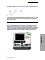
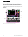
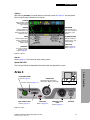
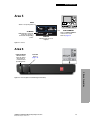
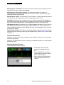
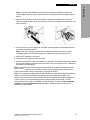
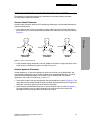
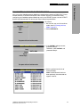
1
LIFEPAK 20e DEFIBRILLATOR/MONITOR ® Operating Instructions LIFEPAK 20e DEFIBRILLATOR /MONITOR ® OPERATING INSTRUCTIONS Important Information !USA Rx Only !USA Device Tracking The U.S. Food and Drug Administration requires defibrillator manufacturers and distributors to track the location of their defibrillators. If the device is located somewhere other than the shipping address or the device has been sold, donated, lost, stolen, exported, destroyed, permanently retired from use, or if the device was not obtained directly from Physio-Control, please do one of the following: register the device at http://www.physio-control.com, call the device tracking coordinator at 1.800.426.4448, or use one of the postage-paid address change cards located in the back of this manual to update this vital tracking information. Text Conventions Throughout these operating instructions, special text characters are used to indicate labels, screen messages, and voice prompts: • Operating control labels: CAPITAL LETTERS such as ON/OFF and SHOCK. • Screen messages and voice prompts: CAPITAL ITALICIZED LETTERS such as CONNECT ELECTRODES. Version History These operating instructions describe LIFEPAK 20e defibrillator/monitor devices with software version 3202609-084 or later. LIFEPAK, FAST-PATCH, DERMA-JEL, QUIK-LOOK, and QUIK-COMBO are registered trademarks of Physio-Control, Inc. ADAPTIV, CODE-STAT, CODE SUMMARY, REDI-PAK, and Shock Advisory System are trademarks of Physio-Control, Inc. Masimo and LNOP are registered trademarks of Masimo Corporation. Microstream, CapnoLine, and FilterLine are registered trademarks of Oridion Systems Ltd. The Oridion medical capnography in this product is covered by one or more of the following US patents: 6,428,483; 6,997,880; 6,437,316; 7,448,229; 7,726,954 and their foreign equivalents. Additional patent applications pending. EDGE System is a trademark of Ludlow Technical Products. Microsoft and Windows are registered trademarks of Microsoft Corporation. Specifications are subject to change without notice. ©2006-2013 Physio-Control, Inc. Publication Date: 11/2013 3313187-007 CONTENTS Preface About Automated External Defibrillation ...................................................................... viii About Defibrillation Therapy ..........................................................................................ix About Noninvasive Pacing ............................................................................................. x About SpO2 Monitoring .................................................................................................. x About ECG Monitoring ................................................................................................... x About EtCO2 Monitoring ................................................................................................xi 1 Safety Information Terms........................................................................................................................... 1-2 General Warnings and Cautions.................................................................................. 1-2 Symbols ....................................................................................................................... 1-4 2 Basic Orientation Introduction .................................................................................................................. 2-2 Unpacking and Inspecting ........................................................................................... 2-2 Controls, Indicators, and Connectors .......................................................................... 2-3 Area 3.................................................................................................................... 2-6 Area 4.................................................................................................................... 2-8 Area 7.................................................................................................................. 2-11 Changing Printer Paper....................................................................................... 2-13 Back View............................................................................................................ 2-14 Side View of CodeManagement Module ............................................................. 2-15 Entering Patient Data................................................................................................. 2-16 Setting Alarms ........................................................................................................... 2-17 Managing Alarms ....................................................................................................... 2-19 Connecting to Power ................................................................................................. 2-20 AC Operation....................................................................................................... 2-20 LIFEPAK 20e Defibrillator/Monitor Operating Instructions ©2006-2013 Physio-Control, Inc. iii Battery Operation .......................................................................................................2-20 LIFEPAK 20e Defibrillator/Monitor Battery ..........................................................2-20 CodeManagement Module Battery ......................................................................2-23 3 Monitoring Monitoring the ECG......................................................................................................3-2 ECG Monitoring Warning.......................................................................................3-2 Selecting ECG Lead and Size ...............................................................................3-2 Adjusting the Systole Tone Volume.......................................................................3-3 Monitoring with the Patient ECG Cable .................................................................3-5 Troubleshooting Tips for ECG Monitoring .............................................................3-7 Monitoring SpO2 ...................................................................................................................................... 3-9 SpO2 Warnings and Cautions................................................................................3-9 When to Use a Pulse Oximeter ...........................................................................3-10 How a Pulse Oximeter Works..............................................................................3-10 SpO2 Monitoring Considerations .........................................................................3-11 SpO2 Monitoring Procedure.................................................................................3-12 SpO2 Waveform...................................................................................................3-12 SpO2 Volume.......................................................................................................3-12 Sensitivity.............................................................................................................3-13 Averaging Time....................................................................................................3-13 Pulse Oximeter Sensors ......................................................................................3-13 Cleaning...............................................................................................................3-13 Troubleshooting Tips for SpO2 ............................................................................3-14 Monitoring EtCO2 .................................................................................................................................. 3-16 EtCO2 Warnings and Cautions ............................................................................3-16 How Capnography Works....................................................................................3-17 EtCO2 Monitoring Waveform Analysis.................................................................3-17 EtCO2 Monitoring Procedure ...............................................................................3-18 CO2 Display .........................................................................................................3-20 CO2 Alarms..........................................................................................................3-20 CO2 Detection......................................................................................................3-21 Cleaning...............................................................................................................3-21 Troubleshooting Tips for EtCO2...........................................................................3-22 4 Therapy General Therapy Warnings and Cautions....................................................................4-2 Therapy Electrode and Standard Paddle Placement ...................................................4-3 Anterior-lateral Placement .....................................................................................4-3 Anterior-posterior Placement .................................................................................4-3 Special Placement Situations ................................................................................4-4 Automated External Defibrillation.................................................................................4-5 AED Warnings .......................................................................................................4-5 AED Setup .............................................................................................................4-5 AED Procedure......................................................................................................4-6 Special AED Setup Options.................................................................................4-10 Troubleshooting Tips for AED Mode....................................................................4-13 Switching from AED to Manual Mode ..................................................................4-14 Manual Defibrillation...................................................................................................4-14 Manual Defibrillation Warnings ............................................................................4-15 Impedance ...........................................................................................................4-15 Defibrillation Procedure .......................................................................................4-16 CPR Metronome ..................................................................................................4-17 iv LIFEPAK 20e Defibrillator/Monitor Operating Instructions Synchronized Cardioversion Procedure.............................................................. 4-18 Remote Synchronization Procedure.................................................................... 4-20 Pediatric Defibrillation ................................................................................................ 4-21 Pediatric Paddle Placement ................................................................................ 4-21 Defibrillation Procedure ....................................................................................... 4-22 Troubleshooting Tips for Defibrillation and Synchronized Cardioversion............ 4-22 Noninvasive Pacing ................................................................................................... 4-25 Noninvasive Pacing Warnings............................................................................. 4-25 Demand and Nondemand Pacing ....................................................................... 4-25 Noninvasive Pacing Procedure ........................................................................... 4-26 Troubleshooting Tips for Noninvasive Pacing ..................................................... 4-27 5 Paddle Accessory Options Therapy Electrodes...................................................................................................... 5-2 About Therapy Electrodes..................................................................................... 5-2 Electrode Placement ............................................................................................. 5-3 Cable Connection.................................................................................................. 5-4 ECG Monitoring and Therapy Procedures ............................................................ 5-4 Replacing and Removing Electrodes .................................................................... 5-5 Testing................................................................................................................... 5-6 Cleaning and Sterilizing......................................................................................... 5-6 Standard Paddle Set (Optional) ................................................................................... 5-7 About the Standard Paddle Set............................................................................. 5-7 Accessing the Pediatric Paddles ........................................................................... 5-7 Replacing the Adult Paddle Attachment................................................................ 5-8 Cleaning the Standard Paddle Set ........................................................................ 5-8 Sterilizable Internal Defibrillation Paddles ................................................................... 5-9 6 Data Management Overview of Data Storage and Retrieval ..................................................................... 6-2 Data Storage ......................................................................................................... 6-2 Report Types......................................................................................................... 6-2 Memory Capacity .................................................................................................. 6-2 CODE SUMMARY Report ........................................................................................... 6-2 Preamble ............................................................................................................... 6-3 Event/Vital Signs Log ............................................................................................ 6-3 Waveform Events .................................................................................................. 6-4 CODE SUMMARY Format .................................................................................... 6-5 Managing Archived Patient Records ........................................................................... 6-7 Entering Archives Mode............................................................................................... 6-7 Printing Archived Patient Reports ................................................................................ 6-7 Transmitting Archived Patient Records ....................................................................... 6-9 Editing Archived Patient Records .............................................................................. 6-10 Deleting Archived Patient Records ............................................................................ 6-11 Overview of Connections for Transmitting Reports ................................................... 6-12 Data Transfer from TrueCPR Device......................................................................... 6-13 Troubleshooting Tips for Data Transmission ............................................................. 6-14 7 Maintaining the Equipment General Maintenance and Testing............................................................................... 7-2 Maintenance and Testing Schedule ...................................................................... 7-2 Daily Auto Test ...................................................................................................... 7-3 User Test............................................................................................................... 7-4 LIFEPAK 20e Defibrillator/Monitor Operating Instructions ©2006-2013 Physio-Control, Inc. v Cleaning.................................................................................................................7-5 Function Checks ....................................................................................................7-5 General Troubleshooting Tips ...................................................................................7-10 Service and Repair.....................................................................................................7-12 Product Recycling Information ...................................................................................7-12 Recycling Assistance...........................................................................................7-12 Preparation ..........................................................................................................7-12 Recycling of Disposable Electrodes ....................................................................7-12 Packaging ............................................................................................................7-12 Warranty.....................................................................................................................7-12 Accessories, Supplies, and Training Tools ...............................................................7-13 8 Defining Setup Options Setup Options ..............................................................................................................8-2 Print Configurations Before Service or Repair.......................................................8-2 Passcode Security .................................................................................................8-2 Entering Setup Options ................................................................................................8-3 General Setup Menu ....................................................................................................8-4 Manual Mode Setup Menu ...........................................................................................8-5 AED Mode Setup Menu ...............................................................................................8-7 CPR Metronome Setup Menu ......................................................................................8-8 Pacing Setup Menu......................................................................................................8-9 Monitoring Menu ..........................................................................................................8-9 Channels Setup Menu ...........................................................................................8-9 Waveform Sets Setup Menu................................................................................8-10 CO2 Setup Menu .................................................................................................8-10 Events Setup Menu....................................................................................................8-10 Alarms Setup Menu....................................................................................................8-11 Printer Setup Menu ....................................................................................................8-11 Auto Print Setup Menu.........................................................................................8-12 Clock Setup Menu......................................................................................................8-12 Reset Defaults Setup Menu .......................................................................................8-13 Print Defaults..............................................................................................................8-13 Send Configuration Setup Menu ................................................................................8-13 Set Passcodes Setup Menu.......................................................................................8-14 Service Mode .............................................................................................................8-14 A Specifications and Performance Characteristics B Clinical Summaries C Screen Messages D Operator’s Checklist E Shock Advisory System F About cprMAX Technology G Docking Station H Electromagnetic Compatibility Guidance Index vi LIFEPAK 20e Defibrillator/Monitor Operating Instructions Preface PREFACE About Automated External Defibrillation About Defibrillation Therapy About Noninvasive Pacing About SpO2 Monitoring About ECG Monitoring About EtCO2 Monitoring LIFEPAK 20e Defibrillator/Monitor Operating Instructions ©2006-2013 Physio-Control, Inc. page viii ix x x x xi vii Preface ABOUT AUTOMATED EXTERNAL DEFIBRILLATION The following considerations and guidelines apply when using the LIFEPAK® 20e defibrillator/ monitor as an automated external defibrillator (AED). Operator Considerations The LIFEPAK 20e defibrillator/monitor, when in AED mode, is a semiautomatic defibrillator that uses a patented Shock Advisory System™. This software algorithm analyzes the patient’s electrocardiographic (ECG) rhythm and indicates whether or not it detects a shockable rhythm. The LIFEPAK 20e defibrillator/monitor in AED mode requires operator interaction to defibrillate the patient. The LIFEPAK 20e defibrillator/monitor in AED mode is intended for use by personnel who are authorized by a physician/medical director and have, at a minimum, the following skills and training: • CPR training. • AED training equivalent to that recommended by the American Heart Association. • Training in the use of the LIFEPAK 20e defibrillator/monitor in AED mode. Indications The AED mode is to be used only on patients in cardiopulmonary arrest. The patient must be unconscious, pulseless, and not breathing normally before using the defibrillator to analyze the patient’s ECG rhythm. In AED mode, the LIFEPAK 20e defibrillator/monitor is not intended for use on pediatric patients less than 8 years old. Contraindications None known. viii LIFEPAK 20e Defibrillator/Monitor Operating Instructions Preface Preface ABOUT DEFIBRILLATION THERAPY Operator Considerations A direct current defibrillator applies a brief, intense pulse of electricity to the heart muscle. The LIFEPAK 20e defibrillator/monitor delivers this energy through disposable electrodes, standard paddles or internal paddles applied to the patient’s chest. Defibrillation is only one aspect of the medical care required to resuscitate a patient with a shockable ECG rhythm. Depending on the situation, other supportive measures may include: • Cardiopulmonary resuscitation (CPR) • Administration of supplemental oxygen • Drug therapy Successful resuscitation is related to the length of time between the onset of a heart rhythm that does not circulate blood (ventricular fibrillation, pulseless ventricular tachycardia) and defibrillation. The American Heart Association has identified the following as critical links in the chain of survival from cardiac arrest: • Early access • Early CPR by first responders or bystanders • Early defibrillation • Early advanced life support The physiological state of the patient may affect the likelihood of successful defibrillation. Thus, failure to resuscitate a patient is not a reliable indicator of defibrillator performance. Patients will often exhibit a muscular response (such as jumping or twitching) during an energy transfer. The absence of such a response is not a reliable indicator of actual energy delivery or device performance. Indications Defibrillation is a recognized means of terminating certain potentially fatal arrhythmias, such as ventricular fibrillation and symptomatic ventricular tachycardia. Delivery of this energy in the synchronized mode is a method for treating atrial fibrillation, atrial flutter, paroxysmal supraventricular tachycardia and, in relatively stable patients, ventricular tachycardia. Contraindications Defibrillation is contraindicated in the treatment of Pulseless Electrical Activity (PEA) such as idioventricular or ventricular escape rhythms, and in the treatment of asystole. LIFEPAK 20e Defibrillator/Monitor Operating Instructions ©2006-2013 Physio-Control, Inc. ix Preface ABOUT NONINVASIVE PACING A noninvasive pacemaker is a device that delivers an electrical stimulus to the heart, causing cardiac depolarization and myocardial contraction. The energy is delivered through large adhesive electrodes placed on the chest. In addition to noninvasive pacing, other supportive measures may be necessary. Among other factors, it is recognized that successful pacing of a patient is related to the length of time between the onset of a dysrhythmia and the initiation of pacing. Rapid pacing and prompt follow-up care are essential. The physiologic state of the patient may affect the likelihood of successful pacing or of skeletal muscle activity. The failure to successfully pace a patient is not a reliable indicator of pacemaker performance. Similarly, the patient’s muscular response to pacing is not a reliable indicator of energy delivered. Refer to the booklet, Noninvasive Pacing: What You Should Know for further information. Indications Noninvasive pacing is indicated for symptomatic bradycardia in patients with a pulse. Contraindications Noninvasive pacing is contraindicated for the treatment of ventricular fibrillation and asystole. ABOUT SPO2 MONITORING A pulse oximeter is a noninvasive device that checks the saturation of oxygen in arterial blood (SpO2). It uses an optical sensor that directs light through the patient’s finger and then measures the received light with a detector. This received light is translated into a saturation percentage and is displayed as an SpO2 reading. Indications A pulse oximeter is indicated for use in any patient who is at risk of developing hypoxemia. Contraindications None known. ABOUT ECG MONITORING The ECG (electrocardiogram) is a recording of the electrical activity of the heart. ECG monitoring allows for identification and interpretation of cardiac rhythms or dysrhythmias and calculation of heart rate. The ECG is obtained by placing either electrodes or paddles on the patient and allows the heart’s electrical activity to be monitored and recorded. x LIFEPAK 20e Defibrillator/Monitor Operating Instructions Preface Preface ABOUT ETCO2 MONITORING The end-tidal carbon dioxide (EtCO2) monitor is a capnograph device that uses non-dispersive infrared spectroscopy to continuously measure the amount of CO2 during each breath and report the amount present at the end of exhalation (EtCO2). The sample is obtained by the side stream method and can be used with intubated or nonintubated patients. Respiration rate is also measured and displayed in breaths per minute. The EtCO2 monitor is a tool to be used in addition to patient assessment. Care should be taken to assess the patient at all times; do not rely solely on the EtCO2 monitor. Indications EtCO2 monitoring is used to detect the level of expired CO2. It is used for monitoring breathing efficacy and treatment effectiveness in acute cardiopulmonary care, for example, to determine if adequate compressions are being performed during CPR or to rapidly detect whether an endotracheal tube has been placed successfully. Contraindications None known. LIFEPAK 20e Defibrillator/Monitor Operating Instructions ©2006-2013 Physio-Control, Inc. xi SAFETY INFORMATION 1 Safety Information This section provides important information to help you operate the LIFEPAK 20e defibrillator/ monitor. Familiarize yourself with all of these terms, warnings, and symbols. Terms General Warnings and Cautions Symbols LIFEPAK 20e Defibrillator/Monitor Operating Instructions ©2006-2013 Physio-Control, Inc. page 1-2 1-2 1-4 1-1 Safety Information TERMS The following terms are used either in these operating instructions or on the LIFEPAK 20e defibrillator/monitor: Danger: Immediate hazards that will result in serious personal injury or death. Warning: Hazards or unsafe practices that may result in serious personal injury or death. Caution: Hazards or unsafe practices that may result in minor personal injury, product damage, or property damage. GENERAL WARNINGS AND CAUTIONS The following are general warning and caution statements. Other specific warnings and cautions are provided as needed in other sections of these operating instructions. WARNINGS! Shock hazard. The defibrillator delivers up to 360 J of electrical energy. Unless properly used as described in these operating instructions, this electrical energy may cause serious injury or death. Do not attempt to operate this device unless thoroughly familiar with these operating instructions and the function of all controls, indicators, connectors, and accessories. Shock hazard. Do not disassemble the defibrillator. It contains no operator serviceable components and dangerous high voltages may be present. Contact authorized service personnel for repair. Shock hazard. To avoid the risk of electrical shock, this equipment must only be connected to a supply mains with protective earth. Shock or fire hazard. Do not immerse any portion of this defibrillator in water or other fluids. Avoid spilling any fluids on defibrillator or accessories. Spilled liquids may cause the defibrillator and accessories to perform inaccurately or fail. Do not clean with ketones or other flammable agents. Do not autoclave or sterilize this defibrillator or accessories unless otherwise specified. Possible fire or explosion. Do not use this device in the presence of flammable gases or anesthetics. Use care when operating this device close to oxygen sources (such as bag-valve-mask devices or ventilator tubing). Turn off gas source or move source away from patient during defibrillation. Possible electrical interference with device performance. Equipment operating in close proximity could emit strong electromagnetic or radio frequency disturbances that could cause electromagnetic interference (EMI) and affect the performance of this defibrillator. EMI may result in improper defibrillator operation, distorted ECG, failure to detect a shockable rhythm, or cessation of pacing. Avoid operating the defibrillator near cauterizers, diathermy equipment, cellular phones, or other portable and mobile RF communications equipment. Maintain equipment separation of at least 1.2 m (4 ft) and do not rapidly key EMS radios on and off. Contact a technical support representative if assistance is required. 1-2 LIFEPAK 20e Defibrillator/Monitor Operating Instructions Safety Information WARNINGS! (CONTINUED) Possible electrical interference. Using cables, electrodes, or accessories not specified for use with this device may result in increased emissions or decreased resistance to electromagnetic interference which could affect the performance of this device or of equipment in close proximity. Use only parts and accessories specified in these operating instructions. Possible electrical interference. This defibrillator may cause electromagnetic interference (EMI) especially during charge and energy transfers. EMI may affect the performance of equipment operating in close proximity. Verify the effects of defibrillator discharge on other equipment prior to using defibrillator in an emergency situation, if possible. Possible electrical interference. 1 Safety Information This defibrillator should not be used adjacent to or stacked with other equipment. If adjacent or stacked use is necessary, the defibrillator should be observed to verify normal operation in the configuration in which it will be used. Possible defibrillator shutdown. When operating on battery power, adhere to battery maintenance and replacement intervals discussed in the Battery Performance and Life section to prevent possible defibrillator shutdown. If the defibrillator shuts down without warning, or if a LOW BATTERY: CONNECT TO AC POWER message appears on the monitor screen, immediately connect the AC power cord to an outlet. Possible device failure. Do not modify the defibrillator or CodeManagement Module. Possible improper defibrillator performance. Changing factory default settings will change the behavior of the device. Changes to the default settings must only be made by authorized personnel. Possible improper defibrillator performance. Using other manufacturers’ cables, electrodes, or batteries may cause the device to perform improperly and invalidates the safety agency certification. Use only the accessories specified in these operating instructions. Possible failure to detect an out of range condition. Reselecting QUICK SET will reset the alarm limits around the patient’s current vital sign values. This may be outside the safe range for the patient. Safety risk and possible equipment damage. MR unsafe: keep the defibrillator away from magnetic resonance imaging (MRI) equipment. LIFEPAK 20e Defibrillator/Monitor Operating Instructions ©2006-2013 Physio-Control, Inc. 1-3 Safety Information SYMBOLS The symbols below may be found in these operating instructions or on various configurations of LIFEPAK 20e defibrillator/monitor and accessories: Defibrillation-proof type CF terminal Defibrillation protected, type BF patient connection Attention, consult accompanying documents Attention, consult accompanying documents. (Symbol has blue background and graphical symbol is white.) Warning, high voltage Type BF patient connection Static sensitive device (SSD) MR unsafe: keep away from magnetic resonance imaging (MRI) equipment Safety ground. Protective earth connection Fuse Equipotential connector Positive terminal Negative terminal Device includes RF transmitter Lot number (batch code): yyww or yymmdd Use by date shown: yyyy-mm-dd Reorder number YYYY Date of manufacture 1-4 LIFEPAK 20e Defibrillator/Monitor Operating Instructions Safety Information Single use only Indoor use only Alarm on Alarm off VF/VT alarm on 1 Safety Information VF/VT alarm silenced Greater than Less than J Joules Adult defibrillation paddle Infant defibrillation paddle Home screen button Battery status indicator (refer to page 2-21) Heart rate/pulse rate indicator (x) Shock count (x) on screen Mark of conformity to applicable European Directives Canadian Standards Association certification for Canada and the United States Recognized component mark for Canada and the United States LIFEPAK 20e Defibrillator/Monitor Operating Instructions ©2006-2013 Physio-Control, Inc. 1-5 Safety Information Mark of conformity to ACA standards DC voltage AC voltage On (power: connection to the AC Mains) Off (power: disconnection from the AC Mains) Power on/off AC power indicator (CodeManagement Module only) [signal] Input [signal] Output CO2 Input CO2 Exhaust This end up Fragile/breakable Handle with care Protect from water Recommended storage temperature 5° to 45°C (41° to 113°F). Storage at extreme temperatures of -20° or 60°C (-4° or 140°F) is limited to seven days. If storage at these temperatures exceeds one week, the electrode shelf-life is reduced. Recycle this item Do not dispose of this product in the unsorted municipal waste stream. Dispose of this product according to local regulations. See www.physio-control.com/recycling for instructions on disposing of this product. System connector/Data in 1-6 LIFEPAK 20e Defibrillator/Monitor Operating Instructions Safety Information Sync in/ECG out LIFEPAK 20e defibrillator/monitor to LIFEPAK 20e defibrillator/monitor cable (refer to Send Configuration Setup Menu, page 8-13) Turn counterclockwise to unlock Switch on Switch off 1 Safety Information Pace arrow, noninvasive pacing Pace arrow, internal pacing R-wave sense marker Event marker Biphasic defibrillation shock Shock button !USA For USA audiences only IPx1 Protected from dripping water per IEC 60529 Serial number CAT Catalog number used for placing orders Manufacturer’s Identification Number (part number) Federal law restricts this device to sale by or on the order of a physician Manufacturer Authorized EC representative LIFEPAK 20e Defibrillator/Monitor Operating Instructions ©2006-2013 Physio-Control, Inc. 1-7 BASIC ORIENTATION This section provides a basic orientation to the LIFEPAK 20e defibrillator/monitor. LIFEPAK 20e Defibrillator/Monitor Operating Instructions ©2006-2013 Physio-Control, Inc. page 2-2 2-2 2-3 2-16 2-17 2-19 2-20 2 Basic Orientation Introduction Unpacking and Inspecting Controls, Indicators, and Connectors Entering Patient Data Setting Alarms Managing Alarms Connecting to Power 2-1 Basic Orientation INTRODUCTION The LIFEPAK 20e defibrillator/monitor with enhanced battery technology is an acute cardiac care response system intended for use by authorized healthcare providers in hospital and clinic settings. The LIFEPAK 20e defibrillator/monitor offers the following optional features: • Semiautomatic defibrillator • Noninvasive pacemaker • Pulse oximeter • Paddle accessories • End-tidal CO2 monitor • Data transmission Note: These operating instructions include information and procedures related to all features of the LIFEPAK 20e defibrillator/monitor and the CodeManagement Module for use with the LIFEPAK 20e defibrillator/monitor. Your LIFEPAK 20e defibrillator/monitor may not have all of these features. For more information, contact your Physio-Control representative or call the number listed on the back cover of these operating instructions. The LIFEPAK 20e defibrillator/monitor is available only with the biphasic defibrillation waveform. For a description of the defibrillation waveform, refer to Appendix A. The LIFEPAK 20e defibrillator/monitor uses QUIK-COMBO® pacing/defibrillation/ECG electrodes or FAST-PATCH® disposable defibrillation/ECG electrodes for ECG monitoring and patient therapy. The therapy cable connects the QUIK-COMBO or FAST-PATCH electrodes to the defibrillator. For more information about QUIK-COMBO or FAST-PATCH electrodes, refer to Section 3 of these operating instructions. The standard paddle set is an accessory for the LIFEPAK 20e defibrillator/monitor and includes adult and pediatric defibrillator (hard) paddles. The standard paddles can be used for QUIK-LOOK® ECG monitoring, defibrillation, and synchronized cardioversion therapies. When using standard paddles, a conductive interface designed for defibrillation, such as defibrillation gel or gel pads, must be used between the paddle electrode surface and the skin. The adult standard paddles can be used for any pediatric patient weighing approximately 10 kg (22 lb) or more as long as the paddles fit completely on the chest and there is at least 2.5 cm (1 in.) of space between the paddle electrodes. Pediatric paddles should be used for patients weighing 10 kg (22 lb) or less or those whose chests are too small to accommodate the adult paddles. Optional internal paddles are also available. For more information about using paddle accessories, refer to Section 5 of these operating instructions. UNPACKING AND INSPECTING After you have removed the LIFEPAK 20e defibrillator/monitor from the shipping container, make sure you have all the required supplies and accessories including cables and ECG paper. Examine the defibrillator and all accessories for any sign of damage that may have occurred during shipping. If possible, save the shipping container and foam inserts in case you have to ship the defibrillator at a later date. 2-2 LIFEPAK 20e Defibrillator/Monitor Operating Instructions Basic Orientation Note the label located to the right of the screen (Figure 2-1). Before the defibrillator/monitor’s first use, plug the power cord into an AC outlet for 3 hours to charge the internal battery. Figure 2-1 Initial Battery Charge If you purchased the CodeManagement Module, you will need to connect it to the LIFEPAK 20e defibrillator/monitor. Refer to the Installation Instructions provided with the CodeManagement Module for more information. CONTROLS, INDICATORS, AND CONNECTORS The following figures provide a brief description of the controls, indicators, and connectors for the LIFEPAK 20e defibrillator/monitor and CodeManagement Module. Figure 2-2 shows the front view of the LIFEPAK 20e defibrillator/monitor and Figure 2-3 shows the front view divided into seven areas. Figure 2-4 through Figure 2-15 show details of each area. Figure 2-16 and Figure 2-17 show back views of the defibrillator with and without the CodeManagement Module. Additional information about areas 3, 4, and 7 follow the applicable figures. The light emitting diode (LED) illuminates (turns on) indicating when the corresponding function is active. For example, the ANALYZE button LED is on when the advisory function is active. DEFIBRILLATOR / MONITOR Recommended Adult VF Dose: XXX-XXX-XXXJ AED Mode ON PRINT AC Mains CODE SUMMARY Service 2 Basic Orientation Analyzing Now--Stand Clear ANALYZE EVENT Speed Dial SpO2 ECG WARNING Hazardous electrical output. For use only by qualified personnel. DANGER Explosion hazard. Do not use in the presence of flammable gases. CO2 Figure 2-2 Front View with Door and CodeManagement Module LIFEPAK 20e Defibrillator/Monitor Operating Instructions ©2006-2013 Physio-Control, Inc. 2-3 Basic Orientation The door on the LIFEPAK 20e defibrillator/monitor hides the manual defibrillation and noninvasive pacing buttons. When the door is closed, the appearance and operation of the device is simplified for the automated external defibrillator (AED) user. To enter manual mode, press the MANUAL button located on the lower left corner of the door. This opens the door and automatically takes the device out of AED mode and allows access to manual mode defibrillation and pacing. After entering manual mode, closing the door does not affect operation. Recommended Adult VF Dose: XXX-XXX-XXXJ DEFIBRILLATOR / MONITOR ON ENERGY SELECT CHARGE Area 7 Area 1 AED MODE ANALYZE LEAD SIZE SYNC PACER RATE Area 5 PRINT CODE SUMMARY ALARMS OPTIONS AC Mains Service PAUSE Speed Dial Area 3 SpO2 ECG Area 2 CURRENT EVENT Area 4 WARNING DANGER Hazardous electrical output. For use only by qualified personnel. Explosion hazard. Do not use in the presence of flammable gases. CO2 Area 6 Figure 2-3 Front View without Door and with CodeManagement Module 2-4 LIFEPAK 20e Defibrillator/Monitor Operating Instructions Basic Orientation Area 1 Adult Ventricular Fibrillation Energy Label Refer to page F-2. 1 ON Switches power on or off. Recommended Adult VF Dose: xxx-xxx-xxxJ AED MODE LED illuminates when AED mode is active. Refer to page 4-5. ANALYZE Activates Shock Advisory System (SAS). Refer to page 4-7. ENERGY SELECT Selects energy levels in manual mode. Refer to page 4-14. CHARGE Charges the defibrillator in manual mode. Refer to page 4-14. SHOCK Discharges defibrillator energy to the patient. Refer to page 4-16. SYNC Activates sychronized mode. Refer to page 4-18. Figure 2-4 Area 1 2 PACER Activates the pacing function. Refer to page 4-25. CURRENT Adjusts pacing current. Refer to page 4-25. RATE Selects pacing rate. Refer to page 4-25. PAUSE Temporarily slows pacing rate. Refer to page 4-25. Figure 2-5 Area 2 LIFEPAK 20e Defibrillator/Monitor Operating Instructions ©2006-2013 Physio-Control, Inc. 2-5 2 Basic Orientation Area 2 Basic Orientation Area 3 3 EVENT Activates userdefined events. Refer to page 2-6. LEAD Changes ECG lead. Refer to page 3-2. HOME SCREEN Returns immediately to Home Screen. Refer to page 2-6. SIZE Changes ECG size. Refer to page 3-2. ALARMS Activates and silences alarms. Refer to page 2-17. LED Illuminates when the Speed Dial is active. Refer to page 2-8. OPTIONS Accesses optional functions. Refer to page 2-7. Figure 2-6 Area 3 Area 3 The following paragraphs provide additional information about the controls shown in "Area 3," page 2-6. Home Screen The home screen is the background screen that displays during ECG monitoring. Pressing HOME SCREEN returns you to the home screen from any menu screen or overlay, except during AED analysis or during manual defibrillation charging and shocking. Event After pressing EVENT, the screen displays the following overlay. Use the Speed Dial to scroll through and select menu choices. Generic is automatically selected when EVENT is pressed and no other selection is made. The selected event and time stamp appear in the message/status area on the screen. Events are printed in the CODE SUMMARY™ Event Log. Refer to page 8-10 for information about configuring events. 2-6 LIFEPAK 20e Defibrillator/Monitor Operating Instructions Basic Orientation Options After pressing OPTIONS, the screen displays the overlay shown in Figure 2-7. Use the Speed Dial to scroll through and select menu choices. PATIENT Enters patient name, patient ID, location, age, and sex. PACING Selects demand or nondemand pacing. Selects internal pacer detection on/off. DATE/TIME Sets the date and time. For changes to take effect, cycle power. ALARM VOLUME Adjusts volume for alarms, tones, and voice prompts. PRINT Selects printer report, format, and mode for printing a current patient report. USER TEST Initiates user test. Refer to page 7-4. ARCHIVES Accesses archived patient records. Refer to page 6-7. Figure 2-7 Options Alarms Refer to page 2-17 for information about setting alarms. Speed Dial LED The indicator LED for the Speed Dial illuminates when the Speed Dial is active. ECG CABLE PORT Refer to page 3-5. Refer to warning, page 2-15. SpO2 CABLE PORT Refer to page 3-11. SPEED DIAL Scrolls through and selects menu items. Refer to this page. IrDA PORT Refer to page 6-12. THERAPY CABLE PORT Refer to page 2-8. 2 Basic Orientation Area 4 4 SPEAKER Figure 2-8 Area 4 LIFEPAK 20e Defibrillator/Monitor Operating Instructions ©2006-2013 Physio-Control, Inc. 2-7 Basic Orientation Area 4 The following paragraphs provide additional information about the Speed Dial and the therapy cable connector shown in Area 4. Speed Dial Use the Speed Dial to scroll through and select the desired menu item either while viewing the monitor screen or while in Options mode. Press the Speed Dial to activate the highlighted menu item. Default menu items are highlighted with a gray background; after a menu item is selected, the background is black. Therapy Cable Connector WARNING! Possible equipment damage and inability to deliver therapy. To protect the therapy cable connector from damage or contamination, keep the therapy cable connected to the defibrillator at all times. Connecting the Therapy Cable To connect a therapy cable connector to the therapy cable port: 1 Orient the therapy cable so that the arrow is on top with the cable angled to the right (refer to Figure 2-9). 2 Insert the therapy cable into the therapy cable connector on the defibrillator until a “click” is sensed. 3 Pull gently on the locking ring to check that the cable is locked in place. Disconnecting the Therapy Cable To disconnect a therapy cable connector from the therapy cable port: 1 Rotate the locking ring on the therapy cable in the direction of the arrow (counterclockwise) until it stops (refer to Figure 2-10). 2 Gently pull out the cable connector. Locking Ring Figure 2-9 Therapy Cable Orientation 2-8 Figure 2-10 Disconnecting the Therapy Cable LIFEPAK 20e Defibrillator/Monitor Operating Instructions Basic Orientation Area 5 5 PRINT Starts or stops the printer. AC MAINS LED illuminates when AC power (line power) is connected and providing power. CODE SUMMARY Prints a CODE SUMMARY critical event record. Refer to page 6-2. SERVICE Indicates that service is required. Figure 2-11 Area 5 Area 6 Power Indicator LED illuminates when AC power (line power) is connected and providing power. CO2 Port Refer to page 3-16. 2 Basic Orientation Figure 2-12 Area 6 (Optional CodeManagement Module) LIFEPAK 20e Defibrillator/Monitor Operating Instructions ©2006-2013 Physio-Control, Inc. 2-9 Basic Orientation Area 7 Note: Your device may have either of two screen formats, depending on the software version. Refer to Figure 2-13 and Figure 2-14 to find the format that matches your device. MONITORING AREA Displays heart rate, time, SpO2, battery status indicator, indicators for VF/VT alarm and selected energy. Refer to page 2-12. WAVEFORM CHANNEL AREA Displays up to two waveform channels. Refer to page 2-12. STATUS MESSAGE AREA Displays status and alarm messages. Figure 2-13 2-10 LIFEPAK 20e Defibrillator/Monitor Operating Instructions Basic Orientation Alarm Icon Time Display CPR Metronome Icon Selected Energy MONITORING PARAMETER AREA Displays patient values and alarm limits. Battery Status Indicator WAVEFORM CHANNEL AREA Displays up to two waveform channels. Refer to page 2-12. STATUS MESSAGE AREA Figure 2-14 Area 7 The following paragraphs provide additional information about Area 7. Monitoring Area—Heart Rate WARNING! Failure to detect a change in ECG rhythm. Heart rate meters may continue to count the internal pacing pulses during occurrences of cardiac arrest or some arrhythmias. Do not rely entirely on heart rate meter alarms. Keep pacemaker patients under close surveillance. QRS detection is essential for using the digital heart rate display, systole tone, synchronized cardioversion, and noninvasive demand pacing. The QRS detector in the LIFEPAK 20e defibrillator/monitor selectively detects QRS complexes. It discriminates against most noise, muscle artifact, T-waves, and other spurious signals. The QRS detect algorithm automatically adjusts itself to the amplitude of the QRS complexes. Changing the gain of the ECG has no effect on QRS detection. For optimum QRS detection performance, use the lead with the greatest QRS amplitude. LIFEPAK 20e Defibrillator/Monitor Operating Instructions ©2006-2013 Physio-Control, Inc. 2-11 2 Basic Orientation The LIFEPAK 20e defibrillator/monitor displays a heart rate between 20 and 300 beats per minute (bpm). A heart rate symbol flashes with each beat. If the heart rate is below 20 bpm or pacing is enabled, the screen displays dashes (– – –). Heart rates above 300 bpm do not yield valid systole tones and the displayed heart rate will not be valid. The heart rate indicator is a tool to be used in addition to patient assessment. Care should be taken to assess the patient at all times and to not rely solely on the displayed heart rate. Basic Orientation Monitoring Area—Pulse Rate. If the ECG is not active, the SpO2 monitor can display pulse rate. The pulse rate source is indicated by PR (SPO2). Monitoring Area—SpO2 (pulse oximeter). The oxygen saturation level is shown as a percentage from 50 to 100. Saturation below 50% is shown as <50%. A fluctuating bar graph represents the pulse signal strength. Monitoring Area—EtCO2. The end-tidal CO2 value is shown as a number representing pressure in mmHg, kPa, or Vol%. Respiratory rate is also shown below the CO2 value. Time Display. The time of day is displayed as hours, minutes, and seconds (HH:MM:SS). To display elapsed time beginning from power on, highlight and select the clock with the Speed Dial. Each time you select the time display, it switches between time of day and elapsed time. CPR Metronome Icon. When the device is in AED mode and the metronome is set up to turn on during CPR, the CPR Metronome icon appears. When the device is in manual mode, you can select the CPR Metronome icon with the Speed Dial to turn the metronome on or off, or change the Age-Airway settings. Battery Status Indicator. The battery status indicator shows the approximate amount of battery charge remaining in the internal Lithium-ion rechargeable battery. (Refer to page 2-20 for further information.) Waveform Channel Area Channel 1. This is the top channel. It displays the primary ECG waveform and is always visible when ECG is displayed. Channel 2. This is the bottom channel. It can display an additional waveform or a continuation of the Channel 1 ECG. Selecting Waveform Channels The monitor power must be turned on. 1 At the home screen, rotate the Speed Dial to highlight Channel 1 or 2. 2 Press the Speed Dial. An overlay appears with the monitoring choices for the selected channel. 3 Rotate and press the Speed Dial to select monitoring choices for that channel. 2-12 LIFEPAK 20e Defibrillator/Monitor Operating Instructions Basic Orientation Changing Printer Paper CAUTION! Possible printer malfunction. Using other manufacturers’ printer paper may cause the printer to function improperly and/or damage the print head. Use only the printer paper specified in these operating instructions. Loading 50 mm Paper The printer is equipped with an out-of-paper sensor to protect the printhead. The sensor automatically turns off the printer if paper runs out or if the printer door is open. To load the paper: 1 2 3 4 5 Press the black button to open the printer door. Remove the empty paper roll. Insert the new paper roll, grid facing upward. Pull out a short length of paper. Push the printer door in to close. Figure 2-15 illustrates the steps for loading 50 mm paper. 2 Basic Orientation Figure 2-15 Printer LIFEPAK 20e Defibrillator/Monitor Operating Instructions ©2006-2013 Physio-Control, Inc. 2-13 Basic Orientation Back View System connector Ground (equipotential) connector Refer to warning, page 2-15. AC power connector ECG/Sync connector Figure 2-16 Back View without CodeManagement Module Refer to warning, page 2-15. ECG/Sync connector AC power connector CO2 exhaust port Refer to warning, page 2-15. System connector Ground (equipotential) connector Figure 2-17 Back View with CodeManagement Module The following paragraphs provide additional information about the back view. 2-14 LIFEPAK 20e Defibrillator/Monitor Operating Instructions Basic Orientation WARNING! Shock hazard. All equipment connected to the system or ECG/sync connector must be battery powered or electrically isolated from AC power according to EN 60601-1. For more information, contact Physio-Control Technical Support. System Connector For LIFEPAK 20e devices that do not have a CodeManagement Module attached, the system connector is used to transfer setup information to another LIFEPAK 20e device or connect to LIFENET® Device Agent. For LIFEPAK 20e devices that have a CodeManagement Module attached, the system connector is used to connect to LIFENET Device Agent. ECG/Sync Connector The ECG/Sync connector provides remote synchronization and real-time ECG output to a third party monitor. CO2 Exhaust Port The CO2 exhaust port connects to a scavenger system when monitoring EtCO2 during use of anesthetics. Side View of CodeManagement Module The CodeManagement Module has the following indicators and connectors on the right side. TrueCPR device port Wireless On/Off switch 2 Basic Orientation On Off Wireless indicators Figure 2-18 Side View of CodeManagement Module The following paragraphs provide additional information about the side view. TrueCPR Device Port The TrueCPR device port is used to transfer data from the TrueCPR™ Coaching Device to the LIFENET System. Only the TrueCPR device should be connected to this port. Refer to "Data Transfer from TrueCPR Device," page 6-13. Note: The TrueCPR device may not be available in all countries. Contact your local Physio-Control representative for more information. LIFEPAK 20e Defibrillator/Monitor Operating Instructions ©2006-2013 Physio-Control, Inc. 2-15 Basic Orientation Wireless On/Off Switch The wireless On/Off switch enables wireless transmission to the LIFENET System. Refer to "Troubleshooting Tips for Data Transmission," page 6-14. Wireless Indicators Indicator 1. LED illuminates when wireless is active. Indicator 2. LED illuminates when the CodeManagement Module is connected to the local network. Indicator 3. LED illuminates when the CodeManagement Module is connected to the LIFENET server. ENTERING PATIENT DATA The following paragraphs describe how to enter or edit a patient’s name, identification (ID), age, or sex. 1 Press OPTIONS. 2 Select PATIENT. To enter or edit a patient’s name or ID: 1 Select LAST NAME, FIRST NAME, or ID. LAST NAME is used as an example (for this procedure). 2-16 LIFEPAK 20e Defibrillator/Monitor Operating Instructions Basic Orientation 2 Rotate the Speed Dial to scroll through the alphabet. 3 Press the Speed Dial to select the desired character. The character appears in the highlighted area. 4 Repeat Step 2 and Step 3 until the name is complete. 5 Scroll and select END to return to the Options/Patient screen as shown previously. There are three additional commands: • BACKSPACE – moves highlight bar left one space • CLEAR – clears all characters in the name field • SPACE – inserts a blank space 6 To exit, press the OPTIONS or HOME SCREEN button. To enter or edit a patient’s age: 1 Select AGE. 2 Rotate the Speed Dial to scroll to the desired age. 3 Press the Speed Dial. To enter or edit a patient’s sex: 2 Basic Orientation 1 Select SEX. 2 Rotate the Speed Dial to highlight MALE or FEMALE. 3 Press the Speed Dial. SETTING ALARMS Alarms for the LIFEPAK 20e defibrillator/monitor can be set to ON or OFF, and are enabled when the monitor is turned on. When the alarms are set to ON, predetermined limits are set. To view these limits, press the ALARMS button. The limits will appear to the right of the parameter value. To change the limits, select QUICK SET. Notes: Alarm limits are not displayed for Respiration Rate or Inspired CO2. Alarm limits are provided in Table 2-1, page 2-19. Although alarm limits for Respiration Rate are not displayed, you can determine whether wide or narrow limits are selected by pressing the ALARMS button. LIFEPAK 20e Defibrillator/Monitor Operating Instructions ©2006-2013 Physio-Control, Inc. 2-17 Basic Orientation When the alarms are set to OFF, you must press the ALARMS button and select QUICK SET to enable the alarms. When you press the ALARMS button, the following Alarms overlay appears: 1 Select QUICK SET to activate the alarms for all active parameters. The quick set limits are set automatically based on the patient’s current vital sign values (refer to Table 2-1). The alarm limits default to the setting (WIDE or NARROW) displayed on the overlay. 2 Select LIMITS to change the alarm limits to WIDE or NARROW (refer to Table 2-1). 3 Select SUSPEND to turn off the audible alarm for up to 15 minutes. If an alarm limit is exceeded while the alarm is silenced, the violated parameter flashes, an alarm message appears, but the alarm tone remains silent. Select VF/VT ALARM to turn on continuous monitoring for ventricular fibrillation and ventricular tachycardia in manual mode. A symbol appears above the primary ECG when the alarm is on . Reselect VF/VT ALARM to turn off this alarm. Note: When the VF/VT alarm is on, you are limited to PADDLES lead or lead II. Refer to "Selecting ECG Lead and Size," page 3-2. Note: The VF/VT alarm will be suspended when the noninvasive pacemaker is on and when standard paddles are attached and PADDLES lead is selected. The alarm is also suspended when the defibrillator is charging or is fully charged. 2-18 LIFEPAK 20e Defibrillator/Monitor Operating Instructions Basic Orientation Table 2-1 Wide and Narrow Alarm Limits Wide Limits Narrow Limits* Low High Low High <60 -20 +35 -10 +25 60–79 -25 +40 -20 +30 80–104 -30 +40 -30 +30 105 -35 +45 -25 +25 SpO2 90 -5 +3 -5 +3 (%) <90 -5 +3 -5 +3 Parameter Heart Rate (bpm) Range Limits Range† Low High Default Limits Low High 30–150 100–250 50 150 50 90–100 85 100 5/0.7 70/9.2 15 50 EtCO2 40/5.3 -10/-1.3 +15/+2.0 -10/-1.3 +15/+2.0 (mmHg/%)1 >40/5.3 -10/-1.3 +15/+2.0 -10/-1.3 +15/+2.0 Inspired CO2 – N/A N/A N/A N/A N/A N/A N/A 8 <15 -8 +8 -4 +4 5-15 10-60 5 30 15 -15 +15 -8 +8 (mmHg/%) 1,2 Respiration Rate (RPM)2 *.Numbers are + from patient’s initial value †.Numbers are absolute range values 1.Limits for kPa are same as % 2.Inspired CO2 and respiration rate alarm limit values are not displayed MANAGING ALARMS The alarm bell symbol indicates when alarms are on or off . When alarms are on and an alarm limit is exceeded, a tone sounds, the violated parameter flashes, and an alarm message appears on the screen. 1 2 3 4 Press ALARMS. This silences the alarm for 2 minutes. Assess the cause of the alarm. Assess the appropriateness of the limits setting (WIDE or NARROW). If the patient is unstable, consider silencing the alarm for up to 15 minutes while attending to the patient. Do not reselect QUICK SET. 5 Once the patient is stable, reselect QUICK SET if necessary. WARNING! Possible failure to detect an out of range condition. Reselecting QUICK SET will reset the alarm limits around the patient’s current vital sign values. This may be outside the safe range for the patient. LIFEPAK 20e Defibrillator/Monitor Operating Instructions ©2006-2013 Physio-Control, Inc. 2-19 2 Basic Orientation To manage an alarm: Basic Orientation When alarms are on, you can silence them preemptively for up to 15 minutes. To silence alarms preemptively: 1 2 3 4 Press ALARMS. Select SUSPEND. Select a silence duration of 2, 5, 10, or 15 minutes. The message ALARMS SUSPENDED appears at the bottom of the screen. CONNECTING TO POWER The LIFEPAK 20e defibrillator/monitor and the optional CodeManagement Module operate on AC (line) power or their internal Lithium-ion batteries. You can switch from battery to AC power or AC power to battery while the device is on and in use by plugging in or unplugging the AC power cord. When the CodeManagement Module is connected to the LIFEPAK 20e defibrillator, one power cord is used to power both the defibrillator and the CodeManagement Module. IMPORTANT: The AC power cord is the safety disconnect mechanism. Maintain clear access to all connections at all times. WARNING! Possible defibrillator shutdown. When operating on battery power, adhere to battery maintenance and replacement intervals discussed in the Battery Performance and Life section to prevent possible defibrillator shutdown. If the defibrillator shuts down without warning, or if a LOW BATTERY: CONNECT TO AC POWER message appears on the monitor screen, immediately connect the AC power cord to an outlet. AC Operation When the LIFEPAK 20e defibrillator/monitor operates on AC power, the AC Mains LED illuminates. When the defibrillator is not in use, the battery charge is best maintained if the power cord is connected to an AC outlet and the defibrillator is turned off. Note: When the CodeManagement Module is attached to the defibrillator, the green LED on the CodeManagement Module and the AC Mains LED on the defibrillator are both illuminated while the device is connected to AC power. BATTERY OPERATION The LIFEPAK 20e defibrillator/monitor and the CodeManagement Module each have an internal battery. Battery operation for the defibrillator is explained below. Battery operation for the CodeManagement Module is explained on page 2-23. LIFEPAK 20e Defibrillator/Monitor Battery The internal Lithium-ion battery is rechargeable and is intended for use when AC power is unavailable or when the device is being used in a portable manner, such as in transport. The defibrillator automatically switches to battery power when the power cord is disconnected from an AC outlet or from the defibrillator. 2-20 LIFEPAK 20e Defibrillator/Monitor Operating Instructions Basic Orientation A new, fully charged battery provides approximately 140 360-joule discharges, 110 minutes of pacing, or approximately 210 minutes of continuous monitoring before the defibrillator turns off. When one flashing red bar appears in the battery status indicator and the LOW BATTERY: CONNECT TO AC POWER message appears on the screen, immediately plug the power cord into an AC outlet to continue use and begin recharging the battery. If low battery messages frequently appear, the battery may need to be replaced. Contact Physio-Control Technical Support or qualified service personnel for assistance. Connect the defibrillator to AC power after each use to recharge the battery. Typically, new fully depleted batteries recharge for 4 hours to regain full capacity. Partially depleted batteries recharge for a time period equivalent to the time the defibrillator was in use. For example, if the defibrillator was used one hour, the required recharge time will be approximately one hour. New batteries or batteries that have been stored for an extended time should be recharged before they are used. Connect the defibrillator to an AC power outlet to bring the battery to full charge. Note: The LIFEPAK 20e defibrillator/monitor is intended to operate with the internal battery installed. In the event of a missing or faulty battery, when plugged into AC power, the device will still operate and the service light will illuminate at power on. Contact Physio-Control Technical Support or qualified service personnel for assistance. Battery Performance and Life Several factors can contribute to the Lithium-ion battery’s performance and life cycle, including: 1 The defibrillator’s use for assisting patients (“on time” and shocks). 2 The defibrillator’s use when the battery is at minimum capacity (low battery condition). 3 The battery’s normal self-discharge rate and the energy used by defibrillator self-tests. To maximize battery performance and life, plug the defibrillator/monitor into an AC outlet to recharge the battery whenever the defibrillator/monitor is not in use. As a reminder, you can set up the LIFEPAK 20e defibrillator/monitor to sound a series of warning beeps, identified as AC LOSS ALERT, whenever the defibrillator is turned off and not plugged into an AC outlet (refer to the "General Setup Menu," page 8-4). Note: Even when properly maintained, the internal rechargeable Lithium-ion battery should be replaced every two years. Battery Status Indicator The battery status indicator approximates the amount of operating time available under battery power for the LIFEPAK 20e defibrillator/monitor. It does not indicate battery status for the CodeManagement Module. The battery status indicator appears on the screen after the defibrillator is turned on. (See Figure 2-13, page 2-10.) The number of illuminated bars indicates the battery capacity and how long the battery will provide power to the defibrillator. A new, fully charged battery will show four green bars, indicating the battery is charged to 100% capacity. As battery charge and battery capacity decreases, the indicator bars decrease incrementally. One flashing red bar indicates a very low or empty battery. Refer to Table 2-2. LIFEPAK 20e Defibrillator/Monitor Operating Instructions ©2006-2013 Physio-Control, Inc. 2-21 2 Basic Orientation Note: While the defibrillator is plugged into AC power, the battery condition is periodically checked. If the battery is missing or is unable to charge, a service LED illuminates the next time the defibrillator is turned on. To check the battery capacity, perform the defibrillation function test (refer to "Maintenance and Testing Schedule," page 7-2). Basic Orientation Table 2-2 Battery Status Indicator Battery Indicator Battery Status Messages and Tones Battery Capacity (percentage) Four green bars None 76–100 Three green bars None 51–75 Two green bars None 26–50 One green bar None 16–25 One yellow bar LOW BATTERY 11–15 Three beeps (one time). Message remains in message area, cycling with others if necessary. One flashing red bar LOW BATTERY: CONNECT TO AC POWER 0–10 Three beeps (every 20 seconds). Message remains in message area, cycling with others if necessary. It is important to note that both charge (voltage) and capacity are factors contributing to the battery status indicator’s display. For example, the battery status indicator displays two green bars when a new battery has 100% capacity and has been charged to 50%. However, an older battery that is 100% charged and only has 50% capacity also displays two green bars. The following demonstrates this example. This battery may either be low in capacity or low in charge as follows: • For a new battery with 100% capacity, this symbol indicates 50% charged (low in charge). • For an older battery with 50% capacity, this symbol indicates 100% charged (low in capacity). 2-22 LIFEPAK 20e Defibrillator/Monitor Operating Instructions Basic Orientation CodeManagement Module Battery The CodeManagement Module has an internal, rechargeable Lithium-ion battery. When the CodeManagement Module is properly connected to the LIFEPAK 20e defibrillator and AC power, the batteries in the defibrillator and CodeManagement Module both recharge. When the device is disconnected from AC power, both the defibrillator and CodeManagement Module automatically switch to battery power. To ensure the CodeManagement Module is always ready for use, keep it plugged into an AC outlet whenever possible. WARNING! Possible CO2 monitoring shutdown. When operating on battery power, adhere to recommended battery charging and replacement intervals to prevent possible CO2 monitoring shutdown. If a CONNECT TO AC POWER message appears on the monitor screen, immediately connect the AC power cord to an outlet. Notes: • One power cord is used to power both the defibrillator and the CodeManagement Module. • If the battery in the CodeManagement Module is low and the LIFEPAK 20e defibrillator is on, the CONNECT TO AC POWER message appears, and three beeps sound every 20 seconds. A new, fully-charged battery for the CodeManagement Module provides 270 minutes of continuous CO2 monitoring. Typically, a new, fully depleted battery recharges for 4 hours to regain full capacity. The battery should be replaced every two years. Battery replacement must be performed by qualified service personnel. 2 Basic Orientation LIFEPAK 20e Defibrillator/Monitor Operating Instructions ©2006-2013 Physio-Control, Inc. 2-23 3 Monitoring MONITORING This section describes the monitoring features of the LIFEPAK 20e defibrillator/monitor. Monitoring the ECG Monitoring SpO2 Monitoring EtCO2 LIFEPAK 20e Defibrillator/Monitor Operating Instructions ©2006-2013 Physio-Control, Inc. page 3-2 3-9 3-16 3-1 Monitoring MONITORING THE ECG The following subsections describe: • ECG Monitoring Warning • Selecting ECG Lead and Size • Adjusting the Systole Tone Volume • Monitoring ECG with Paddles Accessories • Monitoring with the Patient ECG Cable • Troubleshooting Tips for ECG Monitoring ECG Monitoring Warning WARNING! Possible misinterpretation of ECG data. The frequency response of the monitor screen is intended only for basic ECG rhythm identification; it does not provide the resolution required for diagnostic and ST segment interpretation. For diagnostic or ST segment interpretation, or to enhance internal pacemaker pulse visibility, attach the ECG cable. Then print the ECG rhythm in diagnostic frequency response (DIAG). Selecting ECG Lead and Size There are two methods for selecting or changing the ECG lead. Both methods are available on your LIFEPAK 20e defibrillator/monitor. The leads available depend on the ECG cable (3-wire or 5-wire) connected to the device. To change the ECG lead using the LEAD button: 1 Press the LEAD button. If ECG lead appears, the lead automatically changes to paddles. If PADDLES lead appears, the lead automatically changes to lead II. 2 When the Lead menu appears, press the LEAD button again or rotate the Speed Dial to select another lead. The highlighted selection shows the ECG lead. Note: When the VF/VT alarm is on, you are limited to PADDLES lead or lead II in Channel 1. Refer to "Setting Alarms," page 2-17. Note: If one or more lead sets are preconfigured, the menu displays the lead sets. Refer to page 8-9 for information about configuring lead sets. 3-2 LIFEPAK 20e Defibrillator/Monitor Operating Instructions Monitoring You can select or change the ECG size by using the SIZE button or the Speed Dial. If an ECG is in Channel 2, the size is automatically changed to match the Channel 1 size. To select or change the ECG size using the SIZE button: 1 Press the SIZE button. 2 When the Size menu appears, press the SIZE button again. The highlighted selection shows the current ECG size. To select or change the ECG size using the Speed Dial: 1 To obtain the primary ECG, highlight and select CHANNEL 1, and then select SIZE. 2 Change ECG size by rotating the Speed Dial. The highlighted selection shows the current ECG size. Adjusting the Systole Tone Volume To adjust the systole tone volume, highlight and select heart rate (HR) in the monitoring area of the screen. The following overlay appears: 1 Rotate the Speed Dial to the desired volume. 2 Press the home screen to exit. LIFEPAK 20e Defibrillator/Monitor Operating Instructions ©2006-2013 Physio-Control, Inc. 3-3 3 Monitoring To select or change the ECG lead using the Speed Dial: 1 Highlight and select CHANNEL 1, and then select LEAD to obtain the primary ECG lead choices. 2 Change the ECG lead by rotating the Speed Dial. The highlighted selection shows the ECG lead. 3 Repeat Step 1 and Step 2 to select or change displayed waveforms for Channel 2. Monitoring Monitoring ECG with Paddles Accessories Anterior-lateral Placement Anterior-lateral placement is the only placement that should be used for ECG monitoring with paddles accessories. 1 Place either the ♥ or + therapy electrode or the apex paddle lateral to the patient’s left nipple in the midaxillary line, with the center of the electrode in the midaxillary line, if possible. Refer to Figure 3-1. Anterior Sternum Anterior Lateral QUIK-COMBO Electrodes Apex Lateral FAST-PATCH Electrodes Standard Paddles Figure 3-1 Anterior-lateral Placement 2 Place the other therapy electrode or sternum paddle on the patient’s upper right torso, lateral to the sternum and below the clavicle as shown in Figure 3-1. Special Placement Situations When placing therapy electrodes or standard paddles, be aware of the special requirements in the following possible situations. • Obese Patients or Patients with Large Breasts — Apply therapy electrodes or standard paddles to a flat area on the chest, if possible. If skin folds or breast tissue prevent good adhesion, it may be necessary to spread skin folds apart to create a flat surface. • Thin Patients — Follow the contour of the ribs and spaces when pressing the therapy electrodes or standard paddles onto the torso. This limits air spaces or gaps under the electrodes and promotes good skin contact. • Patients with Implanted Pacemakers — If possible, place therapy electrodes or standard paddles away from internal pacemaker generator. • Patients with Implanted Defibrillators — Apply therapy electrodes or standard paddles in the anterior-lateral position and treat this patient as any other patient requiring emergency care. Paddles Monitoring Procedure To monitor using therapy electrodes or standard paddles: 1 Press ON. 2 Prepare the patient’s skin: • Remove excessive chest hair as much as possible. Avoid nicking or cutting the skin. If possible, avoid placing therapy electrodes or standard paddles over broken skin. • Clean and dry the skin. • Do not use alcohol, tincture of benzoin, or antiperspirant to prep the skin. 3-4 LIFEPAK 20e Defibrillator/Monitor Operating Instructions Monitoring 3 Monitoring 3 Apply the therapy electrodes or standard paddles in the anterior-lateral position. For therapy electrodes, confirm that the package is sealed and the Use By date has not passed. For standard paddles, apply conductive gel over the entire electrode surface. 4 Connect the disposable therapy electrodes to the therapy cable. 5 Select PADDLES lead. Monitoring with the Patient ECG Cable There are two ECG cables available for ECG monitoring as shown in Figure 3-2: the 3-wire and 5-wire cables. Connecting the Patient ECG Cable Connect the cable by inserting the main cable connector into the green electrically isolated ECG connector on the monitor. 3-Wire cable 5-Wire cable Figure 3-2 3-wire and 5-wire ECG Cables ECG Monitoring Procedure 1 Press ON. 2 Attach the ECG cable to the monitor. 3 Identify the appropriate electrode sites on the patient as shown in Figure 3-3. RA/R LA/L AHA Labels RA Right Arm LA Left Arm RL* Right Leg LL Left Leg C* Chest IEC Labels R Right L Left N Negative F Foot C Chest C/C RL/N LL/F *Note: Not used for 3-wire cable. Figure 3-3 Electrode Placement for ECG monitoring 4 Prepare the patient’s skin for electrode application: • Shave excessive hair at electrode site. Avoid locating electrodes over tendons and major muscle masses. • For oily skin, clean skin with an alcohol pad. • Dry the site with a brisk rub. LIFEPAK 20e Defibrillator/Monitor Operating Instructions ©2006-2013 Physio-Control, Inc. 3-5 Monitoring 5 Apply ECG electrodes: • Confirm package is sealed and Use By date has not passed. • Attach an electrode to each of the lead wires. • Grasp electrode tab and peel electrode from carrier. • Inspect electrode gel and ensure the gel is intact (discard electrode if gel is not intact). • Hold electrode taut with both hands. Apply the electrode flat to the skin. Smooth tape outwardly. Avoid pressing the center of the electrode. • Secure the trunk cable clasp to the patient’s clothing. 6 Select the lead on the monitor screen. 7 If necessary, adjust ECG size. 8 Press PRINT to obtain an ECG printout. ECG Electrode Requirements Electrode quality is critical for obtaining an undistorted ECG signal. Always check the date code on electrode packages for the Use By date before applying the electrodes to a patient. Do not use electrodes with expired Use By date codes. Disposable electrodes are intended for a single use. For best ECG monitoring results, use silver/silver chloride (Ag/AgCl) electrodes. These electrodes provide a rapid display of post-defibrillation ECG. Leads Off Messages If an electrode or lead wire disconnects during ECG monitoring, the monitor emits an audible alarm and displays a leads off message. The ECG trace becomes a dashed line. The alarm and messages continue until the electrode or lead wire is replaced. Color Coding for ECG Leads The lead wires and the electrode snaps for the patient ECG cable are color coded according to AHA or IEC standards as listed in Table 3-1. Table 3-1 ECG Leads Color Codes Leads AHA Label AHA Color IEC Label IEC Color Limb Leads RA White R Red LA Black L Yellow RL Green N Black LL Red F Green C Brown C Brown Monitoring Patients with Internal Pacemakers The LIFEPAK 20e defibrillator/monitor typically does not use internal pacemaker pulses to calculate the heart rate. However, the monitor may detect internal pacemaker pulses as QRS complexes. This may result in an inaccurate heart rate display. Smaller amplitude internal pacemaker pulses may not be distinguished clearly. For improved detection and display of internal pacemaker pulses, turn on the internal pacemaker detector, and/ or connect the ECG cable, select an ECG lead, and print the ECG in diagnostic frequency response. Large amplitude pacemaker pulses may overload the QRS complex detector circuitry so that no paced QRS complexes are counted. To help minimize ECG pickup of large unipolar pacemaker pulses when monitoring patients with internal pacemakers, place ECG electrodes so the line 3-6 LIFEPAK 20e Defibrillator/Monitor Operating Instructions Monitoring The LIFEPAK 20e defibrillator/monitor annotates internal pacemaker pulses with a hollow arrow on the display and the printed ECG if this feature is configured or selected ON. False annotations of this arrow may occur if ECG artifacts mimic internal pacer pulses. If false annotations occur, you may deactivate the detection feature using the Options/Pacing/Internal Pacer menu (refer to Figure 2-7). Also refer to the "Pacing Setup Menu" in Table 8-9. Patient history and other ECG waveform data, such as wide QRS complexes, should be used to verify the presence of an internal pacemaker. Troubleshooting Tips for ECG Monitoring If problems occur while monitoring the ECG, check the list of observations in Table 3-2 for aid in troubleshooting. For basic troubleshooting problems such as no power, refer to "General Troubleshooting Tips" in Section 7. Table 3-2 Troubleshooting Tips for ECG Monitoring Observation Possible Cause Corrective Action 1 Screen blank and ON LED lighted. Screen not functioning properly. • Print ECG on recorder as backup. • Contact service personnel for repair. 2 Any of these messages displayed: Therapy electrodes are not connected. • Confirm therapy electrode connections. One or more ECG electrodes are disconnected. • Confirm ECG electrode connections. CONNECT ELECTRODES CONNECT ECG LEADS ECG LEADS OFF XX LEADS OFF 3 Poor ECG signal quality. ECG cable is not connected to • Confirm ECG cable connections. monitor. Poor electrode-to-patient adhesion. • Reposition cable and/or lead wires to prevent electrodes from pulling away from patient. • Prepare skin and replace electrode(s). • Select another lead. Broken ECG cable lead wire. • Select PADDLES lead and use standard paddles or therapy electrodes for ECG monitoring. • Check ECG cable continuity. Poor electrode-skin contact. • Reposition cable and/or lead wires to prevent electrodes from pulling away from patient. Secure trunk cable clasp to patient’s clothing. • Prepare skin and replace electrode(s). Outdated, corroded, or driedout electrodes. • Check date codes on electrode packages. • Use only silver/silver chloride electrodes with Use By dates that have not passed. • Leave electrodes in sealed pouch until time of use. LIFEPAK 20e Defibrillator/Monitor Operating Instructions ©2006-2013 Physio-Control, Inc. 3-7 3 Monitoring between the positive and negative electrodes is perpendicular to the line between the pacemaker generator and the heart. Monitoring Table 3-2 Troubleshooting Tips for ECG Monitoring (Continued) Observation Possible Cause Corrective Action Loose connection. Damaged cable or connector/ lead wire. • Check/reconnect cable connections. • Inspect ECG and therapy cables. • Replace if damaged. • Check cable with simulator and replace if malfunction observed. Misplaced electrodes/lead wire. • Confirm correct placement. • Select lead view with optimal QRS detection. Noise because of radio frequency interference (RFI). • Check for equipment causing RFI (such as a radio transmitter) and relocate or turn off equipment power. 4 Baseline wander (low frequency/high amplitude artifact). Inadequate skin preparation. Poor electrode-skin contact. Diagnostic frequency response. • Prepare skin and apply new electrodes. • Check electrodes for proper adhesion. • Print ECG in monitor frequency response. 5 Fine baseline artifact (high frequency/low amplitude). Inadequate skin preparation. Isometric muscle tension in arms/legs. • Prepare skin and apply new electrodes. • Confirm that limbs are resting on a supportive surface. • Check electrodes for proper adhesion. Volume too low. 6 Systole beeps not heard or do not occur QRS amplitude too small to detect. with each QRS complex. • Adjust volume. • Change ECG lead. 7 Monitor displays dashed lines with no ECG leads off messages. PADDLES lead selected but patient connected to ECG cable. • Select one of the limb leads. 8 Heart rate (HR) display different than pulse rate. Monitor is detecting the patient’s internal pacemaker pulses. • Prepare skin and apply new electrodes in different location. • Select lead view with optimal QRS detection. 9 Internal pacemaker Pulses from pacemaker are • Turn on internal pacemaker detector (refer to page 3-6). pulses difficult to see. very small. Monitor the visibility • Connect ECG cable and select of frequency response limits. ECG lead instead of paddles. • Print ECG in diagnostic mode (refer to page 3-5). 3-8 LIFEPAK 20e Defibrillator/Monitor Operating Instructions Monitoring 3 Monitoring MONITORING SpO2 The following paragraphs describe: • SpO2 Warnings and Cautions • When to Use a Pulse Oximeter • How a Pulse Oximeter Works • SpO2 Monitoring Considerations • SpO2 Monitoring Procedure • SpO2 Waveform • SpO2 Volume • Sensitivity • Averaging Time • Pulse Oximeter Sensors • No Implied License • Cleaning • Troubleshooting Tips for SpO2 SpO2 Warnings and Cautions WARNINGS! Shock or burn hazard. Before use, carefully read these operating instructions, the sensor and extension cable directions for use, and precautionary information. Shock or burn hazard. Other manufacturers’ oxygen transducers may cause improper oximeter performance and invalidate safety agency certification. Use only oxygen transducers approved for this product. Inaccurate pulse oximeter readings. Do not use a damaged extension cable or one with exposed electrical contacts. Never use more than one extension cable between the pulse oximeter and the sensor. Inaccurate pulse oximeter readings. Do not use a damaged sensor. Do not alter the sensor in any way. Alterations or modifications may affect performance and/or accuracy. Inaccurate pulse oximeter readings. Sensors exposed to ambient light (such as sunlight, surgical lights, or bilirubin lamp) when incorrectly applied to a patient may exhibit inaccurate saturation readings. Securely place the sensor on the patient and check the sensor’s application frequently to help ensure accurate readings. LIFEPAK 20e Defibrillator/Monitor Operating Instructions ©2006-2013 Physio-Control, Inc. 3-9 Monitoring WARNINGS! (CONTINUED) Inaccurate pulse oximeter readings. Severe anemia, significant blood levels of carboxyhemoglobin or methemoglobin, elevated levels of total bilirubin, intravascular dyes that change usual blood pigmentation, excessive patient movement, venous pulsations, electrosurgical interference, exposure to irradiation and placement of the sensor on an extremity that has a blood pressure cuff, intravascular line or externally applied coloring (such as nail polish) may interfere with oximeter performance. The operator should be thoroughly familiar with the operation of the oximeter prior to use. Inaccurate pulse oximeter readings. The pulsations from intra-aortic balloon support can be additive to the pulse rate. Verify patient’s pulse rate against the ECG heart rate. Skin injury. Prolonged, continuous use of a sensor may cause irritation, blistering, or pressure necrosis of the skin. Check the sensor site regularly based on patient condition and type of sensor. Change the sensor site if skin changes occur. Do not use tape to hold the sensor in place, as this may cause inaccurate readings or damage to the sensor or skin. Possible strangulation. Carefully route patient cabling to reduce the possibility of patient entanglement or strangulation. CAUTION! Possible equipment damage. To avoid damaging the extension cable or the sensor, hold the connectors, rather than the cables, when disconnecting. When to Use a Pulse Oximeter A pulse oximeter is a noninvasive tool that checks the saturation of oxygen in arterial blood (SpO2) and is not to be used as an apnea monitor or as a replacement or substitute for ECG based arrhythmia analysis. It is used for monitoring patients who are at risk of developing hypoxemia. If a pulse oximeter is not used, the only indications of hypoxemia are a patient’s dusky skin, nail beds, and mucous membranes, accompanied by restlessness and confusion. These indications are not conclusive, however, and do not appear until after the patient has developed hypoxemia. Pulse oximetry is to be used in addition to patient assessment. Care should be taken to assess the patient at all times and to not solely rely on the SpO2 reading. If a trend toward patient deoxygenation is indicated, blood samples should be analyzed using laboratory instruments to completely understand the patient’s condition. How a Pulse Oximeter Works A pulse oximeter sensor directs light through a fleshy body site (usually the finger or earlobe). The sensor sends light from the emitting diodes to the receiving detector as shown in Figure 3-4. Oxygen saturated blood absorbs light differently as compared to unsaturated blood. The pulse oximeter translates the amount of light received into a saturation percentage and displays an SpO2 reading. Normal values typically range from 95% to 100% at sea level. 3-10 LIFEPAK 20e Defibrillator/Monitor Operating Instructions Monitoring 3 Monitoring Sensor (holds LEDs and detector) Light emitting diodes Red Infrared Light receiving detector Figure 3-4 How a Pulse Oximeter Works The quality of the SpO2 reading depends on correct sensor size and placement, adequate blood flow through the sensor site, patient motion, and exposure to ambient light. For example, with very low perfusion at the monitored site, readings may read lower than core arterial oxygen saturation. Test methods for accuracy are available by contacting your local Physio-Control representative. SpO2 Monitoring Considerations Each oximeter sensor is applied to a specific site on the patient. Use the following criteria to select the appropriate sensor: • Patient weight • Patient perfusion to extremities • Patient activity level • Available application sites on the patient’s body • Sterility requirements • Anticipated duration of monitoring To help ensure optimal and accurate performance: • Use a dry and appropriately sized sensor. • Keep the sensor site at the same level as the patient’s heart. • Apply the sensor according to the Directions for Use provided with the sensor. • Observe all warnings and cautions noted in the sensor’s Directions for Use. The sensors are sensitive to light. If excessive ambient light is present (such as sunlight, surgical lights, or bilirubin lamp), cover the sensor site with an opaque material to block the light. Failure to do so could result in inaccurate measurements. If patient movements present a problem, consider the following possible solutions: • Be sure the sensor is secure and properly aligned. • Use a new sensor with fresh adhesive backing. • If possible, move the sensor to a less active site. Note: Wrapping the sensor too tightly or using supplemental tape to hold the sensor in place may cause inaccurate measurements. LIFEPAK 20e Defibrillator/Monitor Operating Instructions ©2006-2013 Physio-Control, Inc. 3-11 Monitoring SpO2 Monitoring Procedure The defibrillator controls power to the pulse oximeter. When the defibrillator is turned on, the oximeter turns on and performs a self-test that requires up to 10 seconds. When the defibrillator is turned off, the oximeter also turns off. To conserve battery power, the pulse oximeter goes into “sleep mode” when not in use. Sleep mode is activated within 10 seconds of disconnecting the sensor. During sleep mode, the screen does not display SpO2 information. The oximeter returns to normal mode after detecting a sensor or a patient signal. The oximeter performs the self-test when it returns from sleep mode to active mode. The pulse oximeter measures SpO2 levels between 1% and 100%. When SpO2 levels are between 70% and 100%, oximeter measurements are accurate within ±3 digits. When the pulse oximeter measures SpO2 levels less than 50%, the display shows < 50%. To measure the patient’s SpO2 levels: 1 Connect the SpO2 cable to the monitor. 2 Attach the sensor to the SpO2 cable and the patient. 3 Press ON. 4 Observe the pulse bar for fluctuation. Amplitude of the pulse bar indicates relative signal quality. 5 Adjust sensitivity, averaging time, and SpO2 volume as necessary. SpO2 Waveform The SpO2 waveform can be displayed on waveform Channel 2 by selecting waveform Channel 2 and then selecting SpO2 from the Waveform menu. The SpO2 waveform automatically sizes itself to provide optimum waveform viewing. SpO2 Volume To adjust the pulse tone volume, highlight and select SPO2 on the home screen. The following overlay appears: 1 Highlight and select SPO2 VOLUME. 2 Rotate the Speed Dial to the desired volume. 3 Press the Speed Dial to set the volume. 3-12 LIFEPAK 20e Defibrillator/Monitor Operating Instructions Monitoring The sensitivity setting allows you to adjust the oximeter for differing perfusion states. To adjust the sensitivity to either normal or high, highlight and select SPO2 on the home screen and then select SENSITIVITY. The normal sensitivity setting is the recommended setting for most patients. The high sensitivity setting allows for SpO2 monitoring under low perfusion states such as the severe hypotension of shock. However, when the SpO2 sensitivity is set to high, the signal is more susceptible to artifact. It is recommended that the patient be monitored closely when the high sensitivity setting is in use. Averaging Time The averaging time setting allows you to adjust the time period used to average the SpO2 value. Four time periods are provided for averaging: 4, 8, 12, and 16 seconds. To adjust the averaging time, highlight and select SPO2 on the home screen and select AVERAGING TIME. The averaging time of 8 seconds is recommended for most patients. For patients with rapidly changing SpO2 values, the 4-second time is recommended. The 12- and 16-second periods are used when artifact is affecting the performance of the pulse oximeter. Pulse Oximeter Sensors The Accessory Catalog describes the sensors that can be used with the LIFEPAK 20e defibrillator/monitor. To order compatible sensors and extension cables, refer to the accessories catalog or contact your local Physio-Control sales representative. Masimo Sp02 Sensors Carefully read the directions for use provided with sensors and cables for complete descriptions, instructions, warnings, cautions, and specifications. Compatibility with Nellcor Sensors The LIFEPAK 20e defibrillator/monitor can be ordered to have compatibility with Nellcor sensors. To use the Nellcor sensor with the LIFEPAK 20e defibrillator/monitor, the Masimo MNC-1 adapter cable must be used. Carefully read the directions for use provided with the Nellcor sensors and the Masimo MNC-1 adapter cable for complete description, instructions, warnings, cautions, and specifications. No Implied License Possession or purchase of this oximeter does not convey any express or implied license to use the oximeter with replacement parts which would, alone or in combination with the oximeter, fall within the scope of one or more of the patents relating to this device. Cleaning To clean the sensors, first remove them from the patient and disconnect them from the connector cable. Clean LNC and LNOP DCI sensors by wiping them with a 70% isopropyl alcohol pad. Allow the sensors to dry before placing them on a patient. Do not attempt to sterilize. To clean the connector and adapter cables, first remove them from the defibrillator and then wipe them with a 70% isopropyl alcohol pad. Allow them to dry before reconnecting them to the defibrillator. Do not attempt to sterilize. Note: Do not soak or immerse the cables in any liquid solution. LIFEPAK 20e Defibrillator/Monitor Operating Instructions ©2006-2013 Physio-Control, Inc. 3-13 3 Monitoring Sensitivity Monitoring Troubleshooting Tips for SpO2 Table 3-3 Troubleshooting Tips for SpO2 Observation Possible Cause Corrective Action 1 The oximeter measures a Excessive patient motion. pulse, but there is no oxygen saturation or pulse rate. 2 SpO2 or pulse rate changes rapidly; pulse amplitude is erratic. • • • • Keep patient still. Check that sensor is secure. Relocate sensor. Replace sensor. Patient perfusion may be too low. • Check patient. • Increase sensitivity. Excessive patient motion. • • • • • An electrosurgical unit (ESU) may be interfering with performance. • Move the monitor as far as possible from the ESU. • Plug the ESU and monitor into different circuits. • Move the ESU ground pad as close to the surgical site as possible. • Sensor may be damp, replace it. • Remove sensor extension cable and connect the sensor directly. Keep patient still. Check that sensor is secure. Relocate sensor. Replace sensor. Increase sensitivity. 3 No SpO2 value is displayed. Oximeter may be performing a • Wait for completion. self-test (requires 10 seconds). 4 SPO2: NO SENSOR DETECTED message appears. Sensor is not connected to patient or cable disconnects from device. • Check that sensor and cable are connected properly. 5 SPO2: CHECK SENSOR message appears. Sensor is disconnected from patient or cable. • Attach the sensor. • Check that sensor is secure. Excessive ambient light. • Remove or block light source if possible. • Cover sensor with opaque material, if necessary. Patient has a weak pulse or low blood pressure. • Test sensor on someone else. • Check if patient perfusion is adequate for sensor location. • Check if sensor is secure and not too tight. • Check that sensor is not on extremity with blood pressure cuff or intravascular line. • Change sensor location. 3-14 LIFEPAK 20e Defibrillator/Monitor Operating Instructions Monitoring 3 Monitoring Table 3-3 Troubleshooting Tips for SpO2 (Continued) Observation Possible Cause 6 SPO2: UNKNOWN SENSOR message appears. A sensor is connected to the • Refer to "Pulse Oximeter Sensors," page 3-13 for device that is not compatible sensor compatibility. with the Masimo Sp02 module. 7 SPO2: SEARCHING FOR PULSE message appears. A sensor is connected to the patient and is searching for a pulse. • Wait for completion. 8 SPO2: LOW PERFUSION message appears. Patient has a weak pulse. • Change sensor location. LIFEPAK 20e Defibrillator/Monitor Operating Instructions ©2006-2013 Physio-Control, Inc. Corrective Action 3-15 Monitoring MONITORING ETCO2 The following paragraphs describe: • EtCO2 Warnings and Cautions • How Capnography Works • EtCO2 Monitoring Waveform Analysis • EtCO2 Monitoring Procedure • CO2 Display • CO2 Alarms • CO2 Detection • Cleaning • Troubleshooting Tips for EtCO2 EtCO2 Warnings and Cautions WARNINGS! Fire hazard. Before use, carefully read these operating instructions, the FilterLine® tubing directions for use, and precautionary information. Fire hazard. The FilterLine tubing may ignite in the presence of O2 when directly exposed to laser, electrosurgical devices, or high heat. Use with caution to prevent flammability of the FilterLine tubing. Fire hazard. Flammable anesthetics become mixed with the patient’s air that is sampled by the capnometer. When using the EtCO2 monitor in the presence of flammable gases, such as nitrous oxide or certain other anesthetics, connect the EtCO2 gas port to a scavenger system. Possible inaccurate patient assessment. The EtCO2 monitor is intended only as an adjunct in patient assessment and is not to be used as a diagnostic apnea monitor. An apnea message appears if a valid breath has not been detected for 30 seconds and indicates the time elapsed since the last valid breath. It must be used in conjunction with clinical signs and symptoms. Possible inaccurate CO2 readings. Using other manufacturers’ CO2 accessories may cause the device to perform improperly and invalidate the safety agency certifications. Use only the accessories that are specified in these operating instructions. Possible inaccurate CO2 readings. If calibration is not performed as specified in the Service Manual for the LIFEPAK 20e defibrillator/monitor, the EtCO2 monitor may be out of calibration. A monitor that is out of calibration may provide inaccurate readings. 3-16 LIFEPAK 20e Defibrillator/Monitor Operating Instructions Monitoring 3 Monitoring WARNINGS! (CONTINUED) Possible strangulation. Carefully route the patient tubing (FilterLine) to reduce the possibility of patient entanglement or strangulation. Infection hazard Do not reuse, sterilize, or clean Microstream® CO2 accessories as they are designed for singlepatient one-time use. How Capnography Works An EtCO2 sensor continuously monitors carbon dioxide (CO2) that is inspired and exhaled by the patient. The sensor employs Microstream non-dispersive infrared (IR) spectroscopy to measure the concentration of CO2 molecules that absorb infrared light. The CO2 FilterLine system delivers a sample of the exhaled gases directly from the patient into the CodeManagement Module for CO2 measurement. The low sampling flow rate (50 ml/min) reduces liquid and secretion accumulation and prevents obstruction, which maintains the shape of the CO2 waveform. The CO2 sensor captures a micro sample (15 microliters). This extremely small volume allows for fast rise time and accurate CO2 readings, even at high respiration rates. The Microbeam IR source illuminates the sample cell and the reference cell. This proprietary IR light source generates only the specific wavelengths characteristic of the CO2 absorption spectrum. Therefore, no compensations are required when concentrations of O2, anesthetic agent, or water vapor are present in the exhaled breath. The LIFEPAK 20e defibrillator/monitor is set at the factory to use the capnography Body Temperature Pressure Saturated (BTPS) conversion method. This option corrects for the difference in temperature and moisture between the sampling site and alveoli. The correction formula is 0.97 x the measured EtCO2 value. The BTPS conversion can be turned off in the Setup Options. Refer to "CO2 Setup Menu," page 8-10, for more information. EtCO2 Monitoring Waveform Analysis Valuable information concerning the patient’s expired CO2 can be acquired by examination and interpretation of the waveform. The Phases of the Waveform Figure 3-5 is a graphic representation of a normal capnograph waveform. Four phases of the waveform require analysis. The flat I–II baseline segment (Respiratory Baseline) represents continued inhalation of CO2-free gas. This value normally is zero. The II–III segment (Expiratory Upstroke), a sharp rise, represents exhalation of a mixture of dead space gases and alveolar gases from acini with the shortest transit times. Phase III–IV (Expiratory Plateau) represents the alveolar plateau, characterized by exhalation of mostly alveolar gas. Point IV is the end-tidal (EtCO2) value that is recorded and displayed by the monitor. Phase IV–V (Inspiratory Downstroke), a sharp fall, reflects the inhalation of gases that are CO2-free. Alterations of the normal capnograph or EtCO2 values are the result of changes in metabolism, circulation, ventilation, or equipment function. LIFEPAK 20e Defibrillator/Monitor Operating Instructions ©2006-2013 Physio-Control, Inc. 3-17 Monitoring IV III V I II Figure 3-5 Phases of the Respiratory Waveform Respiratory Baseline. Elevation of the waveform baseline (I–II segment) usually represents rebreathing CO2. This elevation usually is accompanied by gradual increases in the EtCO2 value. Rebreathing CO2 is common in circumstances of artificially produced increased dead space and hypoventilation. Precipitous rises in both baseline and EtCO2 values usually indicate contamination of the sensor. Expiratory Upstroke. In the normal waveform, the rising phase (II–III segment) is usually steep. When this segment becomes less steep, CO2 delivery is delayed from the lungs to the sampling site. The causes of this delay can be physiologic or mechanical and include bronchospasm, obstruction of the upper airway, or obstruction (or kinking) of an endotracheal tube (ETT). Expiratory Plateau. The plateau of the waveform, which represents the remainder of expiration (III-IV segment), should be nearly horizontal. The end of the plateau represents the EtCO2 value. Upward slanting of the expiratory plateau occurs when there is uneven emptying of the alveoli. Similar to the diminished slope of the Expiratory Upstroke, this pattern can occur in asthma, chronic obstructive pulmonary disease (COPD), partial upper-airway obstruction, or partial mechanical obstruction such as a partially kinked ETT. Inspiratory Downstroke. The fall to baseline (IV-V segment) is a nearly vertical drop. This slope can be prolonged and can blend with the expiratory plateau in cases of leakage in the exhale portion of the breathing circuit. The peak EtCO2 value (IV) is often not reached. Relying on the numeric end-tidal value without observing the breathing waveform may obscure the presence of a leak. EtCO2 Monitoring Procedure The EtCO2 monitor is activated when the FilterLine set is attached. Initialization, self-test, and warm-up of the EtCO2 monitor is typically less than 30 seconds, but may take up to two and one-half minutes. Carefully read the Instructions for Use that are provided with the FilterLine for placement instructions, use instructions, warnings, cautions, and specifications. CAUTION! Possible equipment damage. Failure to replace a broken or missing CO2 port door may allow water or particulate contamination of the internal CO2 sensor. This may cause the CO2 module to malfunction. Possible equipment damage. Do not use excessive force when connecting the FilterLine to the CO2 port. This may damage the connector. To monitor EtCO2: 1 Press ON. 2 Select the appropriate EtCO2 accessory for the patient. 3-18 LIFEPAK 20e Defibrillator/Monitor Operating Instructions Monitoring 3 Open the CO2 port door and insert the FilterLine connector. Using the tabs, screw the FilterLine connector into the CO2 port clockwise until it can no longer be turned. Do not use excessive force. 4 Verify that the CO2 area is displayed. The EtCO2 monitor performs the autozero routine as part of the initialization self-test. Note: If you use a ventilation system, do not connect the FilterLine set to the patient/ ventilation system until the EtCO2 monitor has completed its self-test and warm-up. 5 Display CO2 waveform in Channel 2. 6 Connect the CO2 FilterLine set to the patient. 7 Confirm that the EtCO2 value and waveform are displayed. The monitor automatically selects the scale for the best visualization of the waveform. You can change the scale, if desired, as described in the next section. Note: It is possible for the FilterLine set to become loose at the device connection and still have an EtCO2 value and CO2 waveform, but they may be erroneously low. Make sure the FilterLine connection is firmly seated and can no longer be turned. Note: The capnography module performs self-maintenance within the first hour of monitoring and once an hour during continuous monitoring. The self-maintenance includes “autozeroing.” Self-maintenance is also initiated when the surrounding temperature changes 8°C (14.4°F) or more, or the surrounding pressure changes more than 20 mmHg. The CO2 module detects this change and attempts to purge the tubing. To clear the CO2 FILTERLINE PURGING or CO2 FILTERLINE BLOCKAGE messages, remove the FilterLine tubing and reconnect it to the monitor. LIFEPAK 20e Defibrillator/Monitor Operating Instructions ©2006-2013 Physio-Control, Inc. 3-19 3 Monitoring Note: To decrease the likelihood of the FilterLine connection coming loose during use, hand-straighten the tubing after removal from the package before connecting to patient or device. Monitoring CO2 Display The following scales are available to display the CO2 waveform. The LIFEPAK 20e defibrillator/monitor automatically selects the scale based on the measured EtCO2 value. To change the CO2 scale, outline and select the CO2 area using the Speed Dial and then select the desired scale from the scale menu. • Autoscale (default) • 0–20 mmHg (0–4 Vol% or kPa) • 0–50 mmHg (0–7 Vol% or kPa) • 0–100 mmHg (0–14 Vol% or kPa) The CO2 waveform is compressed (displayed at 12.5 mm/sec sweep speed) to provide more data in the 3.7-second screen. There is a slight delay between when the breath occurs and when it appears on the screen. Printouts are at 25 mm/sec. The monitor shows the maximum CO2 value over the last 20 seconds. If the EtCO2 values are increasing, the change can be seen with every breath. However, if the values are continually decreasing, it will take up to 20 seconds for a lower numerical value to be displayed. Because of this, the EtCO2 value may not always match the level of the CO2 waveform. CO2 Alarms The EtCO2 monitor provides: • EtCO2 high and low alarms (controlled by activating Alarms (refer to "Setting Alarms," page 2-17)). • FiCO2 (inspired CO2) alarm (controlled by activating Alarms; automatically set to default values and not adjustable) • Apnea alarm (automatic and not adjustable) • Respiration Rate high and low alarms (controlled by activating Alarms (refer to "Setting Alarms," page 2-17)). Note: The apnea alarm occurs when a breath has not been detected for 30 seconds. The message ALARM APNEA appears in the message area along with the time since the last detected breath. 3-20 LIFEPAK 20e Defibrillator/Monitor Operating Instructions Monitoring A CO2 waveform appears when any CO2 is detected, but CO2 must be greater than 3.5 mmHg for a numerical value to be displayed. However, the CO2 module will not recognize a breath until the CO2 is at least 8 mmHg (1.0% or 1 kPa). Valid breaths must be detected in order for the apnea alarm to function and to count the respiratory rate (RR). When CO2 is not detected in the cardiac arrest situation—for example, the CO2 waveform is either dashes “---” or a flat solid line at or near zero—several factors must be quickly evaluated. Assess for the following causes: Equipment Issues • FilterLine set is disconnected from the endotracheal tube (ETT) • System is purging due to fluid in the patient/sensor connection from ET administration of medications • System is auto-zeroing • FilterLine connection to device is loose Loss of Airway Function • Improper placement of ETT • ETT dislodgment • ETT obstruction Physiological Factors • Apnea • Loss of perfusion • Exsanguination • Massive pulmonary embolism • Inadequate CPR Cleaning Accessories for CO2 monitoring are disposable and are intended for single-patient use. Do not clean and reuse a FilterLine set. Dispose of the contaminated waste according to local protocols. LIFEPAK 20e Defibrillator/Monitor Operating Instructions ©2006-2013 Physio-Control, Inc. 3-21 3 Monitoring CO2 Detection Monitoring Troubleshooting Tips for EtCO2 Table 3-4 Troubleshooting Tips for EtCO2 Observation Possible Cause Corrective Action 1 ALARM APNEA message appears and waveform is solid line at or near zero. No breath has been detected for 30 seconds since last valid breath. • Check the patient. FilterLine connection to device • Twist FilterLine connector clockwise until firmly seated is loose. and can no longer be turned. FilterLine set is disconnected from patient or ETT. • Check ventilation equipment (if used) for leaks or disconnected tubing. 2 CO2 FILTERLINE OFF message appears and waveform is “---”. FilterLine set disconnected from device. • Connect FilterLine set to device port. FilterLine set not securely connected to device. • Twist FilterLine connector clockwise until firmly seated and can no longer be turned. 3 CO2 FILTERLINE PURGING message appears and waveform is “---”. FilterLine set is kinked or clogged with fluid. • Disconnect and then reconnect the FilterLine set. 4 CO2 FILTERLINE BLOCKAGE The message appears after 30 • Disconnect and then reconnect the FilterLine set. message appears and seconds of unsuccessful waveform is “---”. purging. FilterLine set is kinked • Change the FilterLine set. or clogged. 5 CO2 INITIALIZING message appears and waveform is “---”. FilterLine set connected to device while module is initializing. • None. 6 AUTO ZEROING message appears and waveform is “---”. Module is performing selfmaintenance. • None. 7 EtCO2 values are erratic. FilterLine connection to device • Twist FilterLine connector clockwise until firmly seated is loose. and can no longer be turned. 3-22 A leak in the FilterLine set. • Check for connection leaks and line leaks to patient, and correct, if necessary. A mechanically ventilated patient breathes spontaneously or patient is talking. • No action required. LIFEPAK 20e Defibrillator/Monitor Operating Instructions Monitoring 3 Monitoring Table 3-4 Troubleshooting Tips for EtCO2 (Continued) Observation Possible Cause Corrective Action 8 EtCO2 values are consistently higher than expected. Physiological cause such as COPD. • None. Inadequate ventilation. • Check ventilator; increase ventilatory rate/bagging. Patient splinting during breathing. • Supporting measures such as pain relief. Improper calibration. • Contact qualified service personnel. 9 EtCO2 values are consistently lower than expected. 10 CO2 waveform stays elevated for several seconds. FilterLine connection to device • Twist FilterLine connector clockwise until firmly seated is loose. and can no longer be turned. Physiological cause. • See Physiological factors in "CO2 Detection," page 3-21. Hyperventilation. • Check ventilator; decrease ventilatory rate/bagging. Improper calibration. • Contact qualified service personnel. Expiration is prolonged due to bagging technique. • Release bag reservoir completely with expiration. Observe that elevated baseline returns to normal level. 11 Sudden extreme increase in Fluid has entered CO2 module. • Contact qualified service personnel. EtCO2. 12 CHECK CO2 message appears. FilterLine blockage • Disconnect and then reconnect the FilterLine set. • Change the FilterLine set. Exhaust port blockage • Ensure exhaust port on the back of the device is not blocked. • Check exhaust tubing (if present) for blockages or kinks. RF equipment too close to defibrillator • Separate RF equipment from defibrillator. See recommended separation distances in Table 4, page H-4. 13 XXX appears instead of EtCO2 value. CO2 module malfunction. • Turn device off and then on again. • If problem persists, contact qualified service personnel. 14 There is no EtCO2 value and the CO2 waveform is flat. Measured CO2 is less than 3.5 mmHg. • See "CO2 Detection," page 3-21. LIFEPAK 20e Defibrillator/Monitor Operating Instructions ©2006-2013 Physio-Control, Inc. 3-23 Monitoring Table 3-4 Troubleshooting Tips for EtCO2 (Continued) Observation Possible Cause 15 CO2 does not appear on screen when FilterLine is connected. CodeManagement Module not • Contact qualified service personnel. properly connected to defibrillator. 3-24 Corrective Action Low battery voltage. • Connect to AC power. Defective battery in CodeManagement Module. • Contact qualified service personnel. CodeManagement Module malfunction. • Contact qualified service personnel. LIFEPAK 20e Defibrillator/Monitor Operating Instructions THERAPY 4 Therapy This section describes patient therapy. General Therapy Warnings and Cautions Therapy Electrode and Standard Paddle Placement Automated External Defibrillation Manual Defibrillation Pediatric Defibrillation Noninvasive Pacing LIFEPAK 20e Defibrillator/Monitor Operating Instructions ©2006-2013 Physio-Control, Inc. page 4-2 4-3 4-5 4-14 4-21 4-25 4-1 Therapy GENERAL THERAPY WARNINGS AND CAUTIONS WARNINGS! Shock hazard. The defibrillator delivers up to 360 J of electrical energy. When discharging the defibrillator, do not touch the paddle electrode surfaces or disposable therapy electrodes. Shock hazard. If a person is touching the patient, bed, or any conductive material in contact with the patient during defibrillation, the delivered energy may be partially discharged through that person. Clear everyone away from contact with the patient, bed, and other conductive material before discharging the defibrillator. Shock hazard. Do not discharge the defibrillator into the open air. To remove an unwanted charge, change the energy selection, select disarm, or turn off the defibrillator. Possible fire, burns, and ineffective energy delivery. Do not discharge standard paddles on top of therapy electrodes or ECG electrodes. Do not allow standard paddles (or therapy electrodes) to touch each other, ECG electrodes, lead wires, dressings, transdermal patches, etc. Such contact can cause electrical arcing and patient skin burns during defibrillation and may divert defibrillating energy away from the heart muscle. Possible defibrillator shutdown. When operating on battery power, adhere to battery maintenance and replacement intervals discussed in the Battery Performance and Life section to prevent possible defibrillator shutdown. If the defibrillator shuts down without warning, or if a LOW BATTERY: CONNECT TO AC POWER message appears on the monitor screen, immediately connect the AC power cord to an outlet. Possible skin burns. During defibrillation or pacing, air pockets between the skin and therapy electrodes may cause patient skin burns. Apply therapy electrodes so that entire electrode adheres to skin. Do not reposition the electrodes once applied. If the position must be changed, remove and replace with new electrodes. Possible skin burns and ineffective energy delivery. Therapy electrodes that are dried out or damaged may cause electrical arcing and patient skin burns during defibrillation. Do not use therapy electrodes that have been removed from foil package for more than 24 hours. Do not use electrodes beyond expiration date. Check that electrode adhesive is intact and undamaged. Replace therapy electrodes after 50 shocks. Possible interference with implanted electrical device. Defibrillation may cause implanted devices to malfunction. Place standard paddles or therapy electrodes away from implanted devices if possible. Check implanted device function after defibrillation. CAUTION! Possible equipment damage. Prior to using this defibrillator, disconnect all equipment from the patient that is not defibrillatorprotected. 4-2 LIFEPAK 20e Defibrillator/Monitor Operating Instructions Therapy THERAPY ELECTRODE AND STANDARD PADDLE PLACEMENT The following paragraphs describe therapy electrodes and standard paddles placement, including special placement situations. Anterior-lateral Placement Anterior-lateral placement allows for ECG monitoring, defibrillation, synchronized cardioversion, and noninvasive pacing. 1 Place either the ♥ or + therapy electrode, or apex paddle lateral to the patient's left nipple in the midaxillary line, with the center of the electrode in the midaxillary line, if possible. Refer to Figure 4-1. Sternum Anterior Lateral QUIK-COMBO Electrodes 4 Therapy Anterior Lateral FAST-PATCH Electrodes Apex Standard Paddles Figure 4-1 Anterior-lateral Placement 2 Place the other therapy electrode or sternum paddle on the patient’s upper right torso, lateral to the sternum, and below the clavicle as shown in Figure 4-1. Anterior-posterior Placement Anterior-posterior is an alternative position for noninvasive pacing, manual defibrillation, and synchronized cardioversion, but not for ECG monitoring or automated defibrillation. The ECG signal obtained through electrodes in this position is not a standard lead. (For pediatric applications, see "Pediatric Defibrillation," page 4-21.) 1 Place either the ♥ or + therapy electrode over the left precordium as shown in Figure 4-2. The upper edge of the electrode should be below the nipple. Avoid placement over the nipple, the diaphragm, or the bony prominence of the sternum if possible. 2 Place the other electrode behind the heart in the infrascapular area as shown in Figure 4-2. For patient comfort, place the cable connection away from the spine. Do not place the electrode over the bony prominences of the spine or scapula. LIFEPAK 20e Defibrillator/Monitor Operating Instructions ©2006-2013 Physio-Control, Inc. 4-3 Therapy ANTERIOR POSTERIOR ANTERIOR POSTERIOR Po FAST-PATCH Electrodes QUIK-COMBO Electrodes Figure 4-2 Anterior-posterior Placement for Noninvasive Pacing or Defibrillation Special Placement Situations When placing therapy electrodes or standard paddles, be aware of the special requirements in the following possible situations. Synchronized Cardioversion Alternative anterior-posterior placements for cardioversion of supraventricular arrhythmias include: • Place the ♥ or + therapy electrode over the left precordium and the other electrode on the patient’s right posterior infrascapular area – or – • Place the ♥ or + therapy electrode to the right of the sternum and the other electrode on the patient’s posterior left infrascapular area. Obese Patients or Patients with Large Breasts Apply therapy electrodes or standard paddles to a flat area on the chest, if possible. If skin folds or breast tissue prevent good adhesion, it may be necessary to spread skin folds apart to create a flat surface. Thin Patients Follow the contour of the ribs and spaces when pressing the therapy electrodes onto the torso. This limits air spaces or gaps under the electrodes and promotes good skin contact. Patients with Implanted Pacemakers If possible, place therapy electrodes or standard paddles away from the internal pacemaker generator to help prevent damage to the pacemaker. Treat the patient like any other patient requiring care. When operating the defibrillator in AED mode, pacemaker pulses may prevent advisement of an appropriate shock, regardless of the patient’s underlying rhythm. Patients with Implanted Defibrillators Apply therapy electrodes or standard paddles in the anterior-lateral position and treat this patient as any other patient requiring emergency care. If defibrillation is unsuccessful, it may be necessary to try alternate electrode placement (anterior-posterior) due to the insulative properties of implanted defibrillator electrodes. 4-4 LIFEPAK 20e Defibrillator/Monitor Operating Instructions Therapy AUTOMATED EXTERNAL DEFIBRILLATION The following paragraphs include: • AED Warnings • AED Setup • AED Procedure • Special AED Setup Options • Troubleshooting Tips for AED Mode • Switching from AED to Manual Mode AED Warnings WARNING! 4 Therapy Possible misinterpretation of data. Do not analyze while patient is moving or being transported. Motion artifact may affect the ECG signal resulting in an inappropriate SHOCK or NO SHOCK ADVISED message. Motion detection may delay analysis. Stop motion and stand clear of patient during analysis. Pediatric patient safety risk. In AED mode, the LIFEPAK 20e defibrillator/monitor is not intended for use on pediatric patients less than eight years old. AED Setup You can set up the LIFEPAK 20e defibrillator/monitor to turn on in AED mode before placing the defibrillator in use (refer to Section 8). When illuminated, the AED mode LED indicates that the Continuous Patient Surveillance System (CPSS) is active. CPSS automatically monitors the patient ECG for a potentially shockable rhythm. When the ANALYZE button is pressed, the Shock Advisory System (SAS) is activated. SAS is an ECG analysis system that advises the user if it detects a shockable or nonshockable rhythm. The LIFEPAK 20e defibrillator/monitor can be setup to display the ECG waveform in AED mode or to not display a waveform. The operation in AED mode remains the same whether or not the ECG waveform is displayed. When the ECG waveform is set to ON in the setup options (refer to Section 8), the ECG appears with all of the AED messages and prompts, as shown in the screen to the left. LIFEPAK 20e Defibrillator/Monitor Operating Instructions ©2006-2013 Physio-Control, Inc. 4-5 Therapy When the ECG waveform is set to OFF in the setup options, the messages and prompts fill the screen as shown in the screen to the left. When the CPR metronome is set to ON in the setup options (refer to Section 8), the CPR metronome icon is displayed and the metronome sounds automatically during CPR times. You cannot enable or disable the CPR metronome while in AED mode. Refer to "CPR Metronome," page 4-17, for more information. AED Procedure The following descriptions of voice prompts and messages are based on the factory default settings for AED mode. The default settings are consistent with 2010 American Heart Association (AHA) and European Resuscitation Council (ERC) guidelines. Changing the setup options may result in different AED behavior. Refer to Section 8 for setup option choices. 1 Verify that the patient is in cardiopulmonary arrest (unresponsive, not breathing normally, and showing no signs of circulation.) 2 Press ON. 3 Prepare the patient for electrode placement (refer to "Paddles Monitoring Procedure" on page 3-4). The CONNECT ELECTRODES message and voice prompt occur until the patient is connected to the AED. 4 Connect the therapy electrodes to the therapy cable, and confirm cable connection to the defibrillator. 5 Apply the electrodes to the patient's chest in the anterior-lateral position (refer to "Anteriorlateral Placement," page 4-3). 4-6 LIFEPAK 20e Defibrillator/Monitor Operating Instructions Therapy 6 Press the ANALYZE button to initiate analysis. Stop CPR. The PUSH ANALYZE message and voice prompt occur when the patient is properly connected to the AED. The PUSH ANALYZE message will stay on the screen and the analyze LED flashes until ANALYZE is pressed. 7 Follow screen messages and voice prompts provided by the AED. You will see and hear ANALYZING NOW, STAND CLEAR. Do not touch or move The SAS analyzes the patient's ECG and advises either SHOCK ADVISED or NO SHOCK ADVISED. Shock Advised If the AED detects a shockable ECG rhythm, you will see and hear SHOCK ADVISED. The AED begins charging to the setup joule setting for shock #1. A rising tone indicates that the AED is charging. When charging is complete, the AED displays the available energy. You will see and hear STAND CLEAR, ) followed by a “shock ready” tone. The shock LED flashes. Clear everyone away from the patient, bed, or any equipment connected to the patient. PUSH TO SHOCK ( Press the AED. LIFEPAK 20e Defibrillator/Monitor Operating Instructions ©2006-2013 Physio-Control, Inc. button to discharge the 4-7 4 Therapy the patient or therapy cable during analysis. ECG analysis requires approximately 6 to 9 seconds. The analyze LED illuminates during analysis. Therapy Note: If you do not press the button within 60 seconds, the AED disarms the shock button, and the DISARMING message appears. When the button is pressed you will see the message ENERGY DELIVERED indicating energy transfer was completed. When energy transfer is complete the shock counter increases by 1. This will continue to increase incrementally with every energy transfer. After a shock is delivered you will see and hear START CPR. A countdown timer (min:sec format) continues for the duration specified in the CPR TIME 1 setup option. Note: If the CPR metronome is set to be on during CPR times, you will hear audible “tocks” and ventilation prompts or tones. When the CPR countdown time ends, you will see and hear PUSH ANALYZE. This message stays on the screen and the voice prompt will repeat every 20 seconds until you press the ANALYZE button. No Shock Advised If the AED detects a nonshockable rhythm, you will see and hear NO SHOCK ADVISED. The AED will not charge, and a shock can not be delivered. 4-8 LIFEPAK 20e Defibrillator/Monitor Operating Instructions Therapy After a NO SHOCK ADVISED prompt you will see and hear START CPR. A countdown timer (min:sec format) continues for the duration specified in the CPR TIME 2 setup option. (Refer to Section 8). Note: If the CPR metronome is set to be on during CPR times, you will hear audible “tocks” and ventilation prompts or tones. Proper Connection If therapy electrodes are not connected to the therapy cable or not placed on the patient’s chest, the CONNECT ELECTRODES message and voice prompt occur until the patient is connected to the AED. If the therapy cable is not connected to the defibrillator, you will see the CONNECT CABLE message until the cable is connected. If the test plug is connected to the therapy cable when analysis is initiated, the REMOVE TEST PLUG message and voice prompt occurs. After you remove the test plug from the therapy cable, the message and voice prompt CONNECT ELECTRODES occurs until the patient is connected to the AED. LIFEPAK 20e Defibrillator/Monitor Operating Instructions ©2006-2013 Physio-Control, Inc. 4-9 4 Therapy When the CPR countdown time ends, you will see and hear PUSH ANALYZE. This message stays on the screen and the voice prompt will repeat every 20 seconds until you press the ANALYZE button. Therapy Motion Detected If motion is detected during the ECG analysis, you will see and hear MOTION DETECTED, STOP MOTION followed by a warning tone. Analysis is inhibited up to 10 seconds. After 10 seconds, even if motion is still present, the analysis proceeds to completion. Refer to Table 4-1 for possible motion causes and suggested solutions. Continuous Patient Surveillance System When the device is not analyzing the ECG and is not in CPR Time, the Continuous Patient Surveillance System (CPSS) actively monitors the ECG for a potentially shockable rhythm. If a shockable rhythm is detected, you will see and hear PUSH ANALYZE. You should: 1 Confirm the patient is unconscious, pulseless, and not breathing normally. 2 Confirm no motion is present. Stop CPR. 3 Press ANALYZE. The AED begins to analyze the patient’s ECG. For information about changing the defibrillation mode, refer to Section 8. Special AED Setup Options The following descriptions of voice prompts and messages explain special cprMAX technology setup options (refer to Appendix F). Initial CPR - CPR First When the INITIAL CPR option is set to CPR FIRST, you will be prompted to START CPR immediately after the AED is turned on. You will see and hear START CPR. 4-10 LIFEPAK 20e Defibrillator/Monitor Operating Instructions Therapy After 3 seconds, a countdown timer continues for the duration specified in the initial CPR period and you will see and hear IF YOU WITNESSED THE ARREST, PUSH ANALYZE. This provides an opportunity to end the initial CPR early and proceed to analysis. Note: The decision to end CPR early is based on your hospital protocol. • If you did not witness the arrest, you should perform CPR and not press ANALYZE. The INITIAL CPR countdown timer continues for the duration specified in the INITIAL CPR TIME setup option, for example, 90 seconds. When INITIAL CPR TIME ends, you will see and hear PUSH ANALYZE. Initial CPR - Analyze First When the INITIAL CPR option is set to ANALYZE FIRST, you will be prompted to perform analysis after the AED is turned on. CPR is prompted after the AED completes the analysis. If the electrodes are not attached to the patient, you will see and hear CONNECT ELECTRODES before you are prompted to perform analysis. No Shock Advised If the AED detects a nonshockable rhythm, you will be prompted to START CPR. A countdown timer (min:sec format) continues for the duration specified in the INITIAL CPR TIME setup option. (Refer to Section 8). When initial CPR time ends, you will see and hear NO SHOCK ADVISED followed by PUSH ANALYZE. LIFEPAK 20e Defibrillator/Monitor Operating Instructions ©2006-2013 Physio-Control, Inc. 4-11 4 Therapy • If you did witness the arrest, you should press ANALYZE and proceed directly to analysis. This will end the CPR period and you will see and hear ANALYZING NOW, STAND CLEAR. Therapy Shock Advised If the AED detects a shockable rhythm, you will see and hear START CPR followed by IF YOU WITNESSED THE ARREST, PUSH ANALYZE. This provides an opportunity to end the initial CPR early and proceed directly to delivering a shock. • If you did witness the arrest, you should press ANALYZE and proceed directly to shock. This will end the CPR period and you will see and hear SHOCK ADVISED and STAND CLEAR, PUSH TO SHOCK ( ). Proceed according to your training with the AED for delivering the shock. Note: The decision to end CPR early is based on your hospital protocol. • If you did not witness the arrest, you should perform CPR and not press ANALYZE. The INITIAL CPR countdown timer continues for the duration specified in the INITIAL CPR TIME setup option, for example, 90 seconds. When initial CPR time ends, you will see and hear SHOCK ADVISED. Proceed according to your training with the AED for delivering a shock. PreShock CPR Time When PRESHOCK CPR time is set to 15 seconds or more, you are prompted to start CPR immediately after a shockable rhythm is detected, before the shock is delivered. After analysis is complete, you will see and hear START CPR. A countdown timer (min:sec format) continues for the duration specified in the PRESHOCK CPR time setup option (for example, 15 seconds). When CPR time ends you will then see and hear SHOCK ADVISED. Proceed according to your training with the AED for delivering a shock. The SHOCK button is disabled during the preshock CPR interval to avoid accidental shock delivery while the defibrillator is charged and a responder is performing CPR. 4-12 LIFEPAK 20e Defibrillator/Monitor Operating Instructions Therapy Troubleshooting Tips for AED Mode Table 4-1 Troubleshooting Tips for AED Mode Observation Possible Cause Corrective Action 1 CONNECT ELECTRODES message appears. Inadequate connection to defibrillator. • Check for electrode connection. Electrodes do not adhere properly to the patient. • Press electrodes firmly on patient’s skin. • Clean, shave, and dry the patient’s skin as recommended. Electrodes are dry, damaged, or out of date. • Replace the electrodes. Test plug connected to therapy • Disconnect test plug from therapy cable. cable. • Connect electrodes to therapy cable. 3 MOTION DETECTED and STOP MOTION messages appear during analysis. Patient movement. • Stop CPR during analysis. • When patient is being manually ventilated, press ANALYZE after complete exhalation. • Move patient to stable location when possible. Patient movement because of agonal respirations. • Press ANALYZE immediately after exhalation or wait until agonal respirations are slower or absent. Electrical/radio frequency interference. • Move hand-held communication devices or other suspected devices away from the defibrillator when possible. Therapy cable or electrodes disconnected from AED or patient. • Confirm secure connection and press ANALYZE. Shock button not pressed within 60 seconds or door is open. • Press ANALYZE again. • Press SHOCK immediately when directed. 5 Voice prompts sound faint or distorted. Low battery power. • Connect to AC power. 6 LOW IMPEDANCE– RECHARGING message appears. Patient impedance <15 ohms detected. • No action required. 7 Metronome not heard. Metronome only sounds during • No action required. CPR time. 4 DISARMING message appears. Metronome not set to be ON in • Refer to "AED Mode Setup Menu," page 8-7. AED mode. LIFEPAK 20e Defibrillator/Monitor Operating Instructions ©2006-2013 Physio-Control, Inc. 4-13 4 Therapy 2 REMOVE TEST PLUG message appears. Therapy Switching from AED to Manual Mode If the front console door is closed, you can enter manual mode by pressing the MANUAL button located in the lower left corner of the door. This opens the door and automatically takes the defibrillator out of AED mode, allowing you to access manual mode defibrillation and pacing. Note: Closing the door again will not place the defibrillator in AED mode. Pressing ANALYZE while the defibrillator is in manual mode will place the defibrillator in AED mode. If the door is not installed, or to manually switch to manual mode, press one of the following keys: ENERGY SELECT, CHARGE, PACER, LEAD. Depending on the defibrillator’s configuration, continue to manual mode as follows: • Direct. No restrictions to manual mode - access is immediate. • Confirm. A confirmation overlay appears: Select YES to change to manual mode. • Passcode. A passcode overlay appears: Enter the passcode to change to manual mode. Refer to Section 8 for information about changing the defibrillation mode. Note: If the CPR metronome is sounding in AED mode, it continues sounding when the device switches to manual mode. If the CPR metronome is silent in AED mode, it continues to be silent in manual mode. To turn the metronome on or off while in manual mode, use the Speed Dial to select the CPR METRONOME icon. Refer to "CPR Metronome," page 4-17, for more information. MANUAL DEFIBRILLATION The following paragraphs describe: • Manual Defibrillation Warnings • Impedance • Defibrillation Procedure • CPR Metronome • Synchronized Cardioversion Procedure • Remote Synchronization Procedure 4-14 LIFEPAK 20e Defibrillator/Monitor Operating Instructions Therapy Manual Defibrillation Warnings WARNINGS! Possible fire, burns, and ineffective energy delivery. Precordial lead electrodes and lead wires may interfere with the placement of standard paddles or therapy electrodes. Before defibrillation, remove any interfering precordial lead electrodes and lead wires. Shock hazard. Conductive gel (wet or dry) on the paddle handles can allow the electrical energy to discharge through the operator during defibrillation. Completely clean the paddle electrode surfaces, handles, and storage area after defibrillation. Possible patient skin burns. Possible paddle damage and patient skin burns. Discharging the defibrillator with the standard paddle surfaces shorted together can pit or damage the paddle electrode surface. Pitted or damaged paddle surfaces may cause patient skin burns during defibrillation. Discharge the defibrillator only as described in these operating instructions. Possible burns and ineffective energy delivery. A gel pathway on the skin between the standard paddles will cause defibrillating energy to arc between paddles and divert energy away from the heart muscle. Do not allow conductive gel (wet or dry) to become continuous between paddle sites. Possible damage to defibrillator and defibrillator shutdown. When used in conjunction with another defibrillator to deliver more than 360J, one or both defibrillators may be damaged and shutdown may occur due to excessive currents. Avoid simultaneous discharge from both defibrillators and maintain a backup defibrillator in case one or both defibrillators shut down. If the defibrillator shuts down, take the defibrillator out of service and contact a qualified service technician. To use the LIFEPAK 20e defibrillator/monitor primarily as a manual defibrillator, configure the defibrillator before placing the defibrillator in use. To configure the defibrillator, refer to Section 8. Impedance LIFEPAK biphasic defibrillators measure the patient's transthoracic impedance and automatically adjust the defibrillation waveform voltage and current duration to meet the needs of the individual patient. Impedance is measured whenever the defibrillator is charged. To ensure correct patient impedance readings, you should always charge the defibrillator when the standard paddles (hard paddles) or QUIK-COMBO electrodes are in contact with the patient's chest. If the standard paddles are in the paddle wells or touching face to face (shorted paddles) when the defibrillator is charged, the defibrillator limits the available energy to 79 joules This prevents damage to the internal circuits, in the event the energy is discharged while the hard paddles are still in the paddle wells or shorted together. If the defibrillator is charged to 80 joules or more and energy is discharged when the hard paddles are seated in the paddle wells, the display indicates the selected energy available and the automatic printout annotates time, date and Shock 1 79 J. LIFEPAK 20e Defibrillator/Monitor Operating Instructions ©2006-2013 Physio-Control, Inc. 4-15 4 Therapy During defibrillation, air pockets between the skin and standard paddles can cause patient skin burns. Completely cover paddle electrode surfaces with fresh conductive gel and apply 11.3 kg (25 lb) of pressure per paddle during discharge. Therapy If the defibrillator is charged to 80 joules or more with paddles in the paddle wells, and then the paddles are removed and placed on a patient, the defibrillator continues charging to the selected energy and defibrillation may be completed as usual. When charging the defibrillator with the paddles on the patient’s chest, the defibrillator automatically adjusts the waveform voltage and current duration based on the patient's impedance. It is important to understand that this automatic adjustment does not occur when the defibrillator is charged with the paddles seated in the paddle wells. When the paddles or QUIK-COMBO electrodes are on the patient's chest when the defibrillator is charged and the defibrillator measures an impedance of 15 ohms or less, the defibrillator disarms the capacitor and automatically recharges to a lower energy setting. When this condition occurs, the LOW IMPEDANCE-RECHARGING message appears on the display. When charging is complete, defibrillation may be completed as usual. Defibrillation Procedure You can configure the LIFEPAK 20e defibrillator/monitor to automatically sequence energy levels. Refer to "Manual Mode Setup Menu," page 8-5. 1 Press ON. 2 Identify the electrode or paddle sites on the patient. Use either the anterior-lateral or anteriorposterior position as described on page 4-3. 3 Prepare the patient’s skin for electrode application: • If possible, place the patient on a firm surface away from standing water. • Remove clothing from the patient’s upper torso. • Remove excessive hair from the electrode sites; if shaving is necessary, avoid cutting the skin. • Clean the skin and dry it briskly with a towel or gauze. • Do not apply alcohol, tincture of benzoin, or antiperspirant to the skin. 4 Connect the therapy electrodes to the therapy cable, and confirm cable connection to the defibrillator. Note: When in PADDLES lead, if the REMOVE TEST PLUG message appears, disconnect test plug and connect therapy electrodes to QUIK-COMBO therapy cable. 5 Apply therapy electrodes to the patient in anterior-lateral or anterior-posterior position. If using standard paddles, apply conductive gel to the paddles and place paddles on the patient’s chest. 6 Press ENERGY SELECT. 7 Press CHARGE. While the defibrillator is charging, a charging bar appears and a ramping tone sounds, indicating the charging energy level. When the defibrillator is fully charged, an overlay appears (refer to "Defibrillation Procedure," page 4-16). 8 Make certain all personnel, including the operator, stand clear of the patient, bed, and any equipment connected to the patient. 9 Confirm ECG rhythms and available energy. 10 Press the SHOCK button on the defibrillator or the SHOCK buttons on the standard paddles to discharge energy to the patient. For standard paddles, apply firm pressure with both paddles to the patient’s chest, and press both paddle buttons simultaneously to discharge energy to the patient. For safety reasons, the SHOCK button on the defibrillator front panel is disabled when using standard paddles. Note: To disarm (cancel the charge), press the Speed Dial. The defibrillator disarms automatically if shock buttons are not pressed within 60 seconds, or if you change the energy selection after charging begins. Press CHARGE to restart charging. 4-16 LIFEPAK 20e Defibrillator/Monitor Operating Instructions Therapy 11 Observe the patient and the ECG rhythm. If an additional shock is necessary, repeat the procedure beginning at Step 6. Note: If the ABNORMAL ENERGY DELIVERY message appears and the shock is not effective, increase energy, if necessary, and repeat shock. (Also refer to page 4-24.) CPR Metronome When CPR is required during cardiac arrest, the CPR metronome provides audible prompts that guide the user to deliver CPR with proper timing in accordance with the 2010 American Heart Association and European Resuscitation Council CPR guidelines. CPR Metronome Warnings WARNING! CPR Delivered When Not Needed. 4 Therapy The metronome sounds do not indicate information regarding the patient’s condition. Because patient status can change in a short time, the patient should be assessed at all times. Do not perform CPR on a patient who is responsive or is breathing normally. Note: The CPR metronome is a tool to be used as a timing aid during CPR. Assess the patient at all times and provide CPR only when indicated. Provide CPR according to your training and protocols. How the CPR Metronome Works The metronome provides audible “tocks” at a rate of 100/minute to guide the rescuer in performing chest compressions. The metronome also provides audible ventilation prompts (either a tone or verbal “ventilate”) to cue the rescuer when to provide ventilations. The metronome prompts the rescuer to perform CPR at the selected compression to ventilation (C:V) ratio. Age-Airway Considerations The default C:V ratio for the metronome (in both AED and Manual modes) is Adult - No Airway (30:2) because most patients in cardiac arrest are adults who have an initially unsecured airway. In Manual mode, the user can choose the most appropriate C:V ratio based on the patient’s age and current airway status. The Age-Airway selection determines the C:V ratio of the metronome sounds. The default C:V ratios are shown in Table 4-2. Table 4-2 Default Age-Airway C:V Ratios in Manual Mode Age-Airway C:V Ratio Adult - No Airway* 30:2 Adult - Airway** 10:1 Youth - No Airway*** 15:2 Youth - Airway 10:1 * No Airway = No artificial airway in place ** Airway = Advanced artificial airway in place *** Youth = Pre-pubescent child Note: The compression-to-ventilation ratio selections can be set up according to local medical protocols. For more information, refer to "CPR Metronome Setup Menu," page 8-8. LIFEPAK 20e Defibrillator/Monitor Operating Instructions ©2006-2013 Physio-Control, Inc. 4-17 Therapy Activating and Deactivating the Metronome To activate the CPR metronome in Manual mode: CPR Metronome Adult - No Airway Adult - Airway Youth - No Airway Youth - Airway Stop Metronome Adult - No Airway 30:2 1 Use the Speed Dial to select the CPR METRONOME icon. The CPR Metronome menu appears and the metronome is activated using the AdultNo Airway default setting. 2 Use the Speed Dial to highlight and select the desired Age-Airway setting. When the metronome is on, a message appears in the message area that indicates the current Age-Airway selection. Note: The CPR metronome cannot be activated during noninvasive pacing. Note: If the VF/VT alarm is on, it is suspended when the metronome is on to prevent false VF/VT alarms. If other vital sign alarms activate when the metronome is on, the visual indicators occur, but the alarm tone is suppressed until the metronome is deactivated. The metronome provides “tocks” and ventilation prompts continuously until it is deactivated. To stop the metronome, select STOP METRONOME in the CPR Metronome menu. An event is recorded in the CODE SUMMARY Event Log when CPR metronome is turned ON or OFF and when the Age-Airway setting is changed. To adjust the volume of the metronome, press OPTIONS, select ALARM VOLUME, and change the VOLUME. Note: If all Age-Airway selections are set to the same C:V ratio (for example, Adult - No Airway, Adult - Airway, Youth - No Airway, and Youth - Airway all set to 10:1), the CPR metronome always provides “tocks” and ventilation prompts at the set ratio for both AED mode and Manual mode. In this situation, the CPR Metronome menu does not appear when the CPR METRONOME icon is selected during use—selecting the CPR METRONOME icon only activates and deactivates the metronome at the fixed C:V ratio. Synchronized Cardioversion Procedure Note: The LIFEPAK 20e defibrillator/monitor can be configured to remain in synchronous mode or to return to asynchronous mode after discharge. It is important that you know how your defibrillator is configured. Refer to "Manual Mode Setup Menu," page 8-5. 1 Press ON. 2 Attach patient ECG cable and ECG electrodes as described previously on page 3-5. 3 Select lead II or the lead with greatest QRS complex amplitude (positive or negative). Note: To monitor the ECG through therapy electrodes, place the electrodes in the anterior-lateral position and select PADDLES lead. 4-18 LIFEPAK 20e Defibrillator/Monitor Operating Instructions Therapy WARNING! Possible lethal arrhythmia. Ventricular fibrillation may be induced with improper synchronization. DO NOT use the ECG from another monitor (slaving) to synchronize the LIFEPAK 20e defibrillator/monitor discharge. Always monitor the patient’s ECG directly through the ECG cable, therapy cable or use the remote synchronization procedure. Confirm proper placement of the sense markers on the ECG. LIFEPAK 20e Defibrillator/Monitor Operating Instructions ©2006-2013 Physio-Control, Inc. 4-19 4 Therapy 4 Press SYNC. Confirm the sync LED blinks with each detected QRS complex. Note: Press SYNC again to deactivate synchronous mode. 5 Observe the ECG rhythm. Confirm that a triangle sense marker appears near the middle of each QRS complex. If the sense markers do not appear or are displayed in the wrong locations (for example, on the T-wave), select another lead. (It is normal for the sense marker location to vary slightly on each QRS complex.) 6 Prepare the patient’s skin for therapy electrode application as described in Step 3 of Defibrillation Procedure, page 4-16. 7 Connect the therapy electrodes to the therapy cable, and confirm cable connection to the defibrillator. 8 Apply therapy electrodes to the patient in the anterior-lateral or anterior-posterior position. If using standard paddles, apply conductive gel to the paddles and place paddles on the patient’s chest. 9 Press ENERGY SELECT. 10 Press CHARGE. Note: If the REMOVE TEST PLUG message appears, disconnect test plug and connect therapy electrodes to QUIK-COMBO therapy cable and press CHARGE. 11 Make certain all personnel, including operator, stand clear of the patient, bed, and any equipment connected to the patient. 12 Confirm ECG rhythm. Confirm available energy. 13 Press and hold the SHOCK button on the defibrillator until the ENERGY DELIVERED message appears on the screen. For standard paddles, press and hold both SHOCK buttons on the paddles simultaneously until the ENERGY DELIVERED message appears on the screen. Release buttons. For safety reasons, the SHOCK button on the defibrillator is disabled when using standard paddles. Note: To disarm (cancel a charge), press the Speed Dial. The defibrillator disarms automatically if shock buttons are not pressed within 60 seconds, or if you change the energy selection after charging begins. Press CHARGE to restart charging. 14 Observe patient and ECG rhythm. Repeat procedure from Step 4, if necessary. Therapy Remote Synchronization Procedure WARNINGS! Possible lethal arrhythmia. Ventricular fibrillation may be induced with improper synchronization. The hospital’s biomedical engineering staff should perform synchronization delay measurements on the system, as a whole, to ensure that the 60 ms limit for synchronization delay is not exceeded, per requirements as specified in AAMI DF2 (1996). Always confirm proper placement of the sense markers on the ECG. Possible monitor incompatibility If the R-wave synchronization markers do not appear to be nearly simultaneous with the Rwaves on the remote monitor display or are not present, do not proceed with synchronized cardioversion. The LIFEPAK 20e defibrillator/monitor can be configured to receive an ECG source from a remote monitor (such as a bedside ECG monitoring system) by means of the ECG/Sync connector on the back of the defibrillator/monitor. Refer to "Manual Mode Setup Menu," page 8-5. The remote monitor must have a sync out connector and a cable must be provided to make this connection. Refer to the LIFEPAK 20e Defibrillator/Monitor Service Manual for more details. Note: The LIFEPAK 20e defibrillator/monitor can be configured to remain in synchronous mode or to return to asynchronous mode after discharge. It is important that you know how your defibrillator is configured. Refer to "Manual Mode Setup Menu," page 8-5. To perform the synchronized cardioversion using a remote monitoring ECG source: 1 Ensure defibrillator/monitor is connected to AC power. 2 Connect the sync cable to the defibrillator/monitor ECG/Sync connector and the remote monitor. 3 Press ON. 4 Attach the ECG cable from the remote monitor to the patient. 5 Press SYNC on the defibrillator/monitor. 6 Select REMOTE SYNC from the menu. Note: The screen on the defibrillator/monitor will display the message REMOTE SYNC in place of any waveforms. 7 Observe the ECG rhythm on the remote monitor. Confirm that a sense marker appears above each QRS complex. 8 Confirm that the sync LED on the defibrillator/monitor blinks with each detected QRS on the remote monitor. 9 Follow Step 6 through Step 14 from "Synchronized Cardioversion Procedure" provided previously. 4-20 LIFEPAK 20e Defibrillator/Monitor Operating Instructions Therapy PEDIATRIC DEFIBRILLATION Pediatric paddles are part of the standard paddle set (refer to page 5-7). Pediatric Paddle Placement Pediatric paddles should be used for patients weighing less than 10 kg (22 lb) or for patients whose chest size cannot accommodate the adult therapy electrodes. Adult paddles are recommended if the paddles will fit completely on the patient’s chest. Allow at least 2.5 cm (1 in.) of space between the paddles. For neonates with very small chests, pediatric paddles may be too large to place in the anteriorlateral position. In this situation, place paddles in the anterior-posterior position. Holding the paddles against the chest and back will support the patient on his/her side. Anterior-Lateral The following is the standard pediatric paddle placement (refer to Figure 4-3): • Sternum paddle to the patient’s right upper torso, lateral to the sternum and below the clavicle. • Apex paddle lateral to the patient’s left nipple in the midaxillary line, with the center of the paddle in the midaxillary line if possible. Sternum Apex Figure 4-3 Anterior-lateral Paddle Position Anterior-Posterior Place the sternum paddle anteriorly over the left precordium and the apex paddle posteriorly behind the heart in the infrascapular area (refer to Figure 4-4) Apex Sternum Figure 4-4 Anterior-posterior Paddle Position LIFEPAK 20e Defibrillator/Monitor Operating Instructions ©2006-2013 Physio-Control, Inc. 4-21 4 Therapy Do not use the pediatric paddles on adults or older children. Delivery of recommended adult energies through this relatively small electrode surface increases the possibility of skin burns. Therapy Defibrillation Procedure To defibrillate the patient: 1 Press ON to turn on the defibrillator. 2 To access the pediatric paddles, slide the adult paddle forward until it releases. 3 Apply defibrillation gel to the pediatric paddle electrode surfaces. 4 Select the appropriate energy for the weight of the child according to American Heart Association recommendations (or equivalent guidelines). 5 Place the paddles firmly on the patient's chest. 6 Press CHARGE. 7 Make certain all personnel, including the operator, are clear of the patient, the bed, and any equipment connected to the patient. 8 Confirm ECG rhythm and available energy. 9 Press the SHOCK button on the defibrillator or the SHOCK buttons on the standard paddles to discharge energy to the patient. For standard paddles, apply firm pressure with both paddles to the patient’s chest, and press both paddle buttons simultaneously to discharge energy to the patient. For safety reasons, the SHOCK button on the defibrillator front panel is disabled when using standard paddles. Note: To disarm (cancel the charge), press the Speed Dial. The defibrillator disarms automatically if shock buttons are not pressed within 60 seconds, or if you change the energy selection after charging begins. Press CHARGE to restart charging. Note: If the ABNORMAL ENERGY DELIVERY message appears and the shock is not effective, increase energy, if necessary, and repeat shock. (Also refer to page 4-24.) Troubleshooting Tips for Defibrillation and Synchronized Cardioversion Table 4-3 Troubleshooting Tips for Defibrillation and Synchronized Cardioversion Observation Possible Cause Corrective Action 1 Charge time to 360 J exceeds 10 seconds. Battery low. • Connect to AC power. • Defibrillator operating in low temperature environment (<25°C or 77°F). 2 Energy not delivered to patient when SHOCK button(s) are pressed. Defibrillator in sync mode and • Change ECG lead for optimum sensing QRS or QRS complexes are not deactivate SYNC. detected. • Hold shock buttons until Defibrillator in sync mode; discharge occurs or next SHOCK button(s) not pressed detected QRS. and held until next detected QRS. SHOCK button(s) pressed before full charge reached. • Wait for tone and message indicating full charge. Sixty seconds elapsed before • Press SHOCK button(s) within 60 seconds of full charge. after full charge. Energy internally removed. SHOCK button(s) pressed ENERGY selection changed. • Press CHARGE again. Test plug connected to • Disconnect test plug and QUIK-COMBO therapy cable. connect electrodes to QUIK-COMBO therapy cable. 4-22 LIFEPAK 20e Defibrillator/Monitor Operating Instructions Therapy Table 4-3 Troubleshooting Tips for Defibrillation and Synchronized Cardioversion (Continued) Observation Possible Cause Corrective Action 3 REMOVE TEST PLUG message appears. Test plug connected to • Disconnect test plug and QUIK-COMBO therapy cable. connect electrodes to QUIK-COMBO therapy cable. 4 CONNECT CABLE or ENERGY NOT DELIVERED message appears. Therapy cable became • Reconnect cable and press CHARGE again. disconnected and energy was removed internally. 5 ENERGY FAULT message appears (selected and available energy). Defibrillator is out of calibration. 6 DISARMING message appears. Discharge button not pressed • Recharge the defibrillator if desired. within 60 seconds after charge complete. 7 Patient didn’t jump (no muscle response) during defibrillator discharge. • May still transfer energy. • Contact qualified service personnel. Energy selected after charge complete. • Recharge the defibrillator. Therapy cable disconnects. • Reconnect electrode/cable. Patient muscle response is variable and depends on patient condition. Lack of visible response to defibrillation does not necessarily mean the discharge did not occur. • No action needed. Therapy cable not connected • Connect electrodes to therapy cable. to therapy electrodes. LIFEPAK 20e Defibrillator/Monitor Operating Instructions ©2006-2013 Physio-Control, Inc. 4-23 4 Therapy Radio frequency interference • Monitor patient using ECG cable and therapy cable as during ablation procedure. follows: 1 Connect ECG electrodes to patient and ECG cable. 2 Confirm device displays patient’s ECG waveform in Channel 1 in Lead I, II, or III. 3 Connect Therapy electrodes to patient and Therapy cable. 4 Confirm device displays patient’s ECG waveform in Channel 2 in Paddles lead. Therapy Table 4-3 Troubleshooting Tips for Defibrillation and Synchronized Cardioversion (Continued) Observation Possible Cause Corrective Action Open air discharge with 8 ABNORMAL ENERGY DELIVERY message appears standard paddles. and Shock XJ Abnormal annotated on printout. 9 CONNECT ELECTRODES message appears. • Press paddles firmly on patient’s chest when discharging. • Perform test discharges with defibrillation checker. Discharge occurs with standard paddles shorted together. • Refer to warning, page 4-15. Patient impedance out of range. • Increase energy and/or repeat discharges as needed. • Consider replacing disposable therapy electrodes with new. Inadequate connection to defibrillator. • Check for electrode connection. Electrodes do not adhere properly to the patient. • Press electrodes firmly on patient’s skin. • Clean, shave, and dry the patient’s skin as recommended. Electrodes are dry, damaged, • Replace the electrodes. or out of date. 10 CONNECT TO AC POWER message appears. Remote sync is selected and the defibrillator is not connected to AC power. • Connect to AC power. • Press SYNC to turn off remote sync. 11 CONNECT SYNC CABLE TO Remote sync is selected and REMOTE MONITOR message the defibrillator is not appears. connected to the remote monitor. • Connect to remote monitor. • Press SYNC to turn off remote synchronization. 12 LOW IMPEDANCE– RECHARGING message appears. Patient impedance of <15 ohms detected. • No action required. 13 SEARCHING FOR SIGNAL message appears. Remote sync is selected and the defibrillator is qualifying the input signal. • No action required. 4-24 LIFEPAK 20e Defibrillator/Monitor Operating Instructions Therapy NONINVASIVE PACING The LIFEPAK 20e defibrillator/monitor provides noninvasive pacing using QUIK-COMBO electrodes. The following paragraphs include: • Noninvasive Pacing Warnings • Demand and Nondemand Pacing • Noninvasive Pacing Procedure • Troubleshooting Tips for Noninvasive Pacing For information about noninvasive pediatric pacing, refer to the Physio-Control Therapy Electrodes Operating Instructions. 4 Therapy Noninvasive Pacing Warnings WARNINGS! Possible inducement of ventricular fibrillation. Sinus bradycardia may be physiologic in severe hypothermia (i.e., appropriate to maintain sufficient oxygen delivery when hypothermia is present), and cardiac pacing is usually not indicated. Possible interruption of therapy. Observe the patient continuously while the pacemaker is in use. Patient response to pacing therapy, e.g., capture threshold, may change over time. Possible inability to pace. Using other manufacturers’ combination therapy electrodes with this device could cause a decrease in pacing efficacy or the inability to pace because of unacceptably high impedance levels. Possible patient skin burns. Prolonged noninvasive pacing may cause patient skin irritation and burns, especially with higher pacing current levels. Discontinue noninvasive pacing if skin becomes burned and another method of pacing is available. Demand and Nondemand Pacing The noninvasive pacemaker can be used for either demand (synchronous) or nondemand (asynchronous) pacing modes. The demand mode is used for most patients. In the demand mode, the LIFEPAK 20e defibrillator/ monitor/pacemaker inhibits pacing when it senses the patient’s own beats (intrinsic QRSs). In demand mode, if the ECG amplitude is too low to detect the patient’s beats, or if an ECG lead becomes detached so that the ECG rhythm is not present, the pacemaker generates pacing pulses asynchronously. This means that the pacemaker generates pacing pulses at the selected rate, regardless of the patient’s ECG rhythm. Asynchronous or nondemand mode can be selected if noise or artifact interferes with proper sensing of QRS complexes. Press the OPTIONS button to access the nondemand mode. (Refer to page 2-7.) LIFEPAK 20e Defibrillator/Monitor Operating Instructions ©2006-2013 Physio-Control, Inc. 4-25 Therapy The LIFEPAK 20e defibrillator/monitor has an integrated pulse oximeter that can be used in conjunction with a noninvasive pacemaker to help confirm capture. To confirm capture, compare the pulse rate measured by the oximeter to the set pacing rate of the pacemaker. Noninvasive Pacing Procedure ECG monitoring during pacing must be performed with the ECG electrodes and patient ECG cable. Pacing therapy electrodes cannot be used to monitor ECG rhythm and deliver pacing current at the same time. Be sure to place the therapy electrodes in the proper locations as described in the pacing procedure. Improper electrode placement may make a difference in the capture threshold. To pace, perform the following: 1 Press ON. 2 Connect the patient ECG cable, apply ECG electrodes to the ECG cable and patient, and select Lead I, II, or III. To receive the best monitoring signal, ensure there is adequate space between the ECG electrodes and the therapy electrodes. 3 Identify the QUIK-COMBO electrode sites on the patient. For pacing, use either the anteriorlateral or anterior-posterior position (refer to page 4-3). 4 Prepare patient's skin for electrode application as described in Step 3 of the Defibrillation Procedure. 5 Apply QUIK-COMBO electrodes to the patient. 6 Connect the therapy electrodes to the therapy cable. 7 Press PACER. Confirm the LED illuminates, indicating that the power is on. Note: If the REMOVE TEST PLUG message appears, disconnect test plug and connect therapy electrodes to QUIK-COMBO therapy cable. 8 Observe the ECG rhythm. Confirm that a triangle sense marker appears near the middle of each QRS complex. If the sense markers do not appear or are displayed in the wrong location (for example, on the T-wave), select another lead. (It is normal for the sense marker location to vary slightly on each QRS complex.) 9 Press RATE or rotate the Speed Dial to select the desired pacing rate. Note: The RATE button changes the rate in 10 pulse per minute (ppm) increments; the Speed Dial changes the rate in 5 ppm increments. 10 Press CURRENT or rotate the Speed Dial to increase current until electrical capture occurs. For each delivered pacing stimulus, the PACER indicator flashes off and a positive pace marker displays on the ECG waveform. 11 Palpate the patient's pulse or check blood pressure and compare the SpO2 pulse rate with the set pacing rate to assess for mechanical capture. Consider use of sedation or analgesia if patient is uncomfortable. Note: The CURRENT button changes the current in 10 mA increments; the Speed Dial changes the current in 5 mA increments. Note: To change rate or current during pacing, press RATE or CURRENT, and then rotate the Speed Dial. Note: To interrupt pacing and view the patient's intrinsic rhythm, press and hold the PAUSE button. This causes the pacer to pace at 25% of the set rate. Release the PAUSE button to resume pacing at the set rate. 12 To stop pacing, reduce current to zero or press PACER. Note: To defibrillate and stop noninvasive pacing, press ENERGY SELECT or charge the defibrillator. Pacing automatically stops. Proceed with defibrillation. 4-26 LIFEPAK 20e Defibrillator/Monitor Operating Instructions Therapy If the monitor detects ECG leads off during pacing, pacing continues at a fixed rate until the ECG lead is reattached. During fixed-rate pacing, the pacemaker delivers pulses at the set pace rate regardless of any intrinsic beats that the patient may have. The monitor continues to display the pacing rate (ppm) and the current (mA). To reestablish demand pacing, reattach the ECG lead. While pacing, visually monitor the patient at all times, do not rely on the ECG LEADS OFF warning to detect changes in pacing function. Routinely assess the ECG for proper sensing, pace pulse delivery, electrical capture, and mechanical capture. If pacing electrodes detach during pacing, the CONNECT ELECTRODES and PACING STOPPED messages appear and an alarm sounds. The pacing rate is maintained and the current resets to 0 mA. Reattaching the pacing electrodes silences the alarm and removes the CONNECT ELECTRODES message. The current remains at 0 mA until you increase the current manually. Troubleshooting Tips for Noninvasive Pacing 4 Therapy Table 4-4 Troubleshooting Tips for Noninvasive Pacing Observation Possible Cause Corrective Action 1 Device does not function when PACER is pressed. Power off. • Check if power is ON. Low battery. • Connect to AC power. 2 PACER LED on, but CURRENT (MA) will not increase. Therapy electrodes off. • Check for message displayed. • Inspect therapy cable and electrode connections. 3 PACER LED on, Pacing rate set below patient's intrinsic rate. • Increase pacing rate. Pacer oversensing (ECG artifact, ECG size too high). • Establish clean ECG; decrease ECG size. • Select nondemand pacing. PACER button pressed off. • Press PACER and increase the current. Internal error detected. Service message indicates an internal failure. • Check for service indicator. • Cycle power and start pacing again. • Obtain service by qualified service personnel. Therapy electrode off. • Check for message. Check pacing cable and electrode connections. ENERGY SELECT or CHARGE • Press PACER and increase current. • Check for service message. • Cycle power and start pacing again. CURRENT (MA) >0, but pace markers absent (not pacing). 4 Pacing stops spontaneously. pressed. Radio frequency interference. LIFEPAK 20e Defibrillator/Monitor Operating Instructions ©2006-2013 Physio-Control, Inc. • Move radio equipment away from pacemaker. 4-27 Therapy Table 4-4 Troubleshooting Tips for Noninvasive Pacing (Continued) Observation Possible Cause Corrective Action 5 Monitor screen displays distortion while pacing. ECG electrodes not optimally placed with respect to pacing electrodes. • Reposition electrodes away from pacing electrodes. Patient response to pacing is highly variable with respect to capture threshold and ECG distortion. • Select another lead (I, II, or III). • Consider changing pacing rate. 6 Capture does not occur with pacing stimulus. Current (mA) set too low. • Increase pacing current. (Administer sedation/ analgesia as needed.) 7 CONNECT ELECTRODES message appears. Pacing cable or electrode disconnected. • Reconnect and set current. Electrodes not adhering to skin. • Prepare skin. Electrodes outdated. • Apply new electrodes and set current. 8 Pacing stops Internal error detected. spontaneously and PACER FAULT message appears. • Cycle power and start pacing again. • Obtain service by qualified service personnel. 9 REMOVE TEST PLUG message appears. Test plug connected to therapy cable. • Disconnect test plug from therapy cable. • Connect electrodes to therapy cable. 10 Intrinsic QRS complexes not sensed when pacing. ECG amplitude too low to be sensed. • Select another lead. Intrinsic QRS complexes are occurring during pacemaker's refractory period. • Adjust pacing rate. Patient’s heart rate falls below set pacing rate. • Appropriate pacemaker function assess patient. During standby pacing, ECG lead disconnects. • Reconnect ECG lead. 12 Set pacing rate (ppm) and ECG paced rate do not appear to match. Internal error detected. • Print ECG and calculate the pace rate. 13 Improper sensing (for example, sensing on T-waves). QRS complex too small. T-wave too large. • Select another lead. 11 Pacing starts spontaneously. 4-28 LIFEPAK 20e Defibrillator/Monitor Operating Instructions PADDLE ACCESSORY OPTIONS Therapy Electrodes Standard Paddle Set (Optional) Sterilizable Internal Defibrillation Paddles page 5-2 5-7 5-9 5 Paddle Accessory Options LIFEPAK 20e Defibrillator/Monitor Operating Instructions ©2006-2013 Physio-Control, Inc. 5-1 Paddle Accessory Options THERAPY ELECTRODES The following paragraphs describe: • About Therapy Electrodes • Electrode Placement • Cable Connection • ECG Monitoring and Therapy Procedures • Replacing and Removing Electrodes • Testing • Cleaning and Sterilizing About Therapy Electrodes There are two pre-gelled, self-adhesive therapy electrodes available: QUIK-COMBO pacing/ defibrillation/ECG electrodes and FAST-PATCH defibrillation/ECG electrodes (Figure 5-1). QUIK-COMBO electrodes are used for defibrillation, synchronized cardioversion, ECG monitoring, and pacing. FAST-PATCH electrodes can be used for defibrillation, synchronized cardioversion, and ECG monitoring, but not for pacing. To use FAST-PATCH electrodes with the LIFEPAK 20e defibrillator/monitor requires the addition of a FAST-PATCH defibrillation adapter cable. Figure 5-1 QUIK-COMBO and FAST-PATCH Electrodes A QUIK-COMBO or FAST-PATCH electrode set: • Is a substitute for standard paddles. • Provides a Lead II monitoring signal when placed in the anterior-lateral position. • Quickly restores the ECG trace on the monitor following defibrillation. To help prevent electrode damage: • Do not fold the electrodes. • Do not trim the electrodes. • Do not crush, fold, or store the electrodes under heavy objects. • Store therapy electrodes in a cool, dry location. These electrodes are designed to withstand environmental temperature fluctuations between -40° to 50°C (-40° to 122°F). Continuous exposure to temperatures above 23°C (73°F) reduces the shelf life of electrodes. There are several types of QUIK-COMBO electrodes available as described in Table 5-1. 5-2 LIFEPAK 20e Defibrillator/Monitor Operating Instructions Paddle Accessory Options Table 5-1 QUIK-COMBO Electrodes Type Description QUIK-COMBO Electrodes, with .6 m (2 ft) of lead wire, designed for patients weighing 15 kg (33 lb) or more. QUIK-COMBO - RTS Electrodes, providing a radio-transparent electrode and lead wire set, designed for patients weighing 15 kg (33 lb) or more. Electrodes designed for patients weighing 15 kg (33 lb) or QUIK-COMBO with REDI-PAK™ more and allow preconnection of the electrode set to the preconnect system device while maintaining electrode shelf life and integrity. Pediatric QUIK-COMBO Electrodes designed for patients weighing 15 kg (33 lb) or less. FAST-PATCH electrodes can be used on pediatric patients if the placement meets conditions noted in the following paragraphs. Usually, these conditions can be met by patients weighing 15 kg (33 lb) or more. Electrode Placement When using QUIK-COMBO or FAST-PATCH electrodes, ensure that the electrodes: • Fit completely on the chest as described on page 3-4 or page 4-3. • Have at least 2.5 cm (1 in.) of space between electrodes. • Do not overlap bony prominences of sternum or spine. To place the electrodes: Figure 5-2 Peeling the Liner from the Electrode 3 Place the electrodes in the anterior-lateral or anterior-posterior position, as described on page 3-4 or page 4-3, depending on the therapy to be provided and special placement considerations. 4 Starting from one edge, firmly press the electrode on the patient’s chest to eliminate air pockets between the gel surface and the skin. Firmly press all adhesive edges to the skin. Note: Once applied, therapy electrodes should not be repositioned. LIFEPAK 20e Defibrillator/Monitor Operating Instructions ©2006-2013 Physio-Control, Inc. 5-3 5 Paddle Accessory Options 1 Prepare the patient for electrode placement: • Remove all clothing from the patient’s chest. • Remove excessive chest hair as much as possible. Avoid nicking or cutting the skin if using a shaver or razor. If possible, avoid placing the electrodes over broken skin. • Clean and dry the skin. If there is ointment on the patient’s chest, use soap and water to clean the skin. Briskly wipe the skin dry with a towel or gauze. This mildly abrades the skin and removes oils, dirt, and other debris for better electrode adhesion to the skin. Do not use alcohol, tincture of benzoin, or antiperspirant to prepare the skin. 2 Slowly peel back the protective liner on the electrodes, beginning with the cable connection end (refer to Figure 5-2). Paddle Accessory Options Cable Connection To connect QUIK-COMBO electrodes to the QUIK-COMBO therapy cable: 1 Open the protective cover on the QUIK-COMBO therapy cable connector (refer to Figure 5-3). 2 Insert the QUIK-COMBO electrode connector into the therapy cable connector by aligning the arrows and pressing the connectors firmly together for proper attachment. QUIK-COMBO electrode connector Therapy cable connector Figure 5-3 Connecting QUIK-COMBO Electrodes to Therapy Cable To properly connect FAST-PATCH electrodes to the FAST-PATCH defibrillation adapter cable and ensure energy delivery: 1 Attach the defibrillation cable to the electrode post (before applying electrodes to the patient, when possible). 2 Support the electrode post when attaching the defibrillation cable (refer to Figure 5-4). Firmly press the cable onto the electrode until a click is heard or felt. Figure 5-4 Connecting FAST-PATCH Electrodes to Defibrillation Cable 3 Pull up gently on the connector to confirm that the defibrillation cable is securely connected to the electrode. Note: If you are reattaching the defibrillation cable to an electrode that is already on the patient, lift the adhesive edge under the electrode post slightly and place your finger under the post. Connect the cable as described in the preceding steps. ECG Monitoring and Therapy Procedures WARNINGS! Possible patient skin burns. Do not use Pediatric QUIK-COMBO electrodes on adults or larger children. Delivery of defibrillation energies equal to or greater than 100 joules (typically used on adults) through these smaller electrodes increases the possibility of skin burns. Possible pediatric patient skin burns. Noninvasive pacing may cause patient skin irritation and burns, especially with higher pacing current levels. Inspect underlying skin of the ♥ electrode frequently after 30 minutes of continuous pacing. Discontinue noninvasive pacing if skin burn develops and another method of pacing is available. On cessation of pacing, immediately remove or replace electrodes with new ones. For adult patients, follow the procedures for ECG monitoring, AED defibrillation, manual defibrillation, synchronized cardioversion, and pacing described in Section 3 or Section 4. 5-4 LIFEPAK 20e Defibrillator/Monitor Operating Instructions Paddle Accessory Options For pediatric patients, follow the procedures for ECG monitoring, manual defibrillation, synchronized cardioversion, and pacing except for the following: • Select the appropriate defibrillation energy for the weight of the pediatric patient according to the American Heart Association (AHA) recommendations or local protocol. Using energy levels of 100 joules or greater is likely to cause burns. • When pacing, frequently inspect the patient’s skin under the heart electrode for signs of burns. Note: The amount of pacing current needed for capture is similar to the pacing current needed for adults. Replacing and Removing Electrodes Replace QUIK-COMBO, QUIK-COMBO RTS, QUIK-COMBO REDI-PAK, or FAST-PATCH Plus electrodes with new electrodes after 50 defibrillation shocks or 24 hours on the patient’s skin, or after 8 hours of continuous pacing. Replace pediatric QUIK-COMBO electrodes after 25 defibrillation shocks or 24 hours on the patient’s skin, or after 8 hours of continuous pacing. To remove QUIK-COMBO or FAST-PATCH electrodes from the patient: 1 Slowly peel back the electrode from the edge, supporting the skin as shown in Figure 5-5. Figure 5-5 Removing Therapy Electrodes from Skin 2 Clean and dry the patient’s skin. 3 When replacing electrodes, adjust the electrode positions slightly to help prevent skin burns. 4 Close the protective cover on the QUIK-COMBO therapy cable connector when the cable is not in use. To disconnect the defibrillation cable from the FAST-PATCH electrodes: 5 Paddle Accessory Options 1 Press down around the electrode post. 2 Pinch the snap connector with the fingers of the other hand and pull straight up (refer to Figure 5-6). Figure 5-6 Disconnecting Defibrillation Cable from FAST-PATCH Electrodes WARNING! Possible cable damage and ineffective energy delivery or loss of monitoring. Improper disconnection of the defibrillation cable may damage the cable wires. This can result in failure to deliver energy or loss of ECG signal during patient care. Position the cable so that it will not be pulled, snagged, or tripped over. Do not disconnect the defibrillation cable snap connectors from electrode posts or posts on testing devices by pulling on the cable. Disconnect the cable by pulling each cable connector straight out (refer to Figure 5-8). LIFEPAK 20e Defibrillator/Monitor Operating Instructions ©2006-2013 Physio-Control, Inc. 5-5 Paddle Accessory Options Figure 5-7 Disconnecting Defibrillation Cable from Test Post Testing As part of your defibrillator test routine, inspect and test the QUIK-COMBO therapy cable or FAST-PATCH defibrillation adapter cable. Daily inspection and testing will help ensure that the defibrillator and therapy cables are in good operating condition and are ready for use when needed. (Refer to "Maintaining the Equipment," page 7-1 and the "LIFEPAK® 20e Defibrillator/ Monitor Operator’s Checklist," page D-1.) Note: During the daily auto test and the user test, energy is discharged through the therapy cable, testing the defibrillation component of the therapy cable. Performing the therapy cable test on the Operator's Checklist checks the sensing component of the therapy cable. Complete therapy cable integrity is checked when both tests are performed. If you detect any discrepancy during inspection and testing, remove the therapy cable from use and immediately notify a qualified service technician. Cleaning and Sterilizing QUIK-COMBO and FAST-PATCH electrodes are not sterile or sterilizable. They are disposable and are to be used for a single patient application. Do not autoclave, gas sterilize, immerse in fluids, or clean electrodes with alcohol or solvents. 5-6 LIFEPAK 20e Defibrillator/Monitor Operating Instructions Paddle Accessory Options STANDARD PADDLE SET (OPTIONAL) The following paragraphs describe: • About the Standard Paddle Set • Accessing the Pediatric Paddles • Replacing the Adult Paddle Attachment • Cleaning the Standard Paddle Set Figure 5-8 illustrates the standard paddles’ features. Sternum Apex SHOCK button CHARGE button Charges the defibrillator. SHOCK button Discharges defibrillator energy. Both SHOCK buttons must be pressed simultaneously to deliver energy. Figure 5-8 Standard Paddles About the Standard Paddle Set A standard paddle set: • Can be used instead of QUIK-COMBO therapy electrodes. • Provides Lead II monitoring signal when held in the anterior-lateral position. • Is used for defibrillation, synchronized cardioversion, and QUIK-LOOK® ECG checks. To help prevent standard paddles damage: • Handle with care to prevent damage to paddle surfaces. 5 Paddle Accessory Options • Store in paddle wells on the device to protect the electrode surface. • Clean dried or wet gel from the electrode surface after each use. The standard paddle set consists of two parts: 1 The handle assembly, which includes the pediatric paddle 2 The adult paddle attachment Features of the QUIK-LOOK defibrillation paddles can be used with both the pediatric paddle and adult paddle attachment. Accessing the Pediatric Paddles To access the pediatric paddles: 1 Grasp the standard paddle handle with one hand and the bottom of the adult paddle electrode with the other hand. 2 Slide the paddle handle back until you hear a click (refer to Figure 5-9). 3 Lift the paddle handle away from the adult attachment. LIFEPAK 20e Defibrillator/Monitor Operating Instructions ©2006-2013 Physio-Control, Inc. 5-7 Paddle Accessory Options 4 The pediatric paddle is now exposed and ready for use (refer to Figure 5-10). Adult paddle attachment Pediatric paddle Figure 5-9 Accessing a Pediatric Paddle Figure 5-10 Pediatric Paddle (Bottom) Replacing the Adult Paddle Attachment To replace the adult paddle attachment: 1 Hold the adult paddle attachment with one hand and the standard handle with the other hand. 2 Fit the pediatric paddle onto the adult paddle attachment. 3 Slide the paddle handle forward until you hear a click. (Refer to Figure 5-11.) Adult paddle attachment Pediatric paddle Figure 5-11 Replacing a Pediatric Paddle Each adult paddle attachment has a contact spring plate that transfers energy from the pediatric paddle to the adult paddle. Routinely inspect the spring plates and pediatric paddle surfaces to make sure that they are clean and intact. Cleaning the Standard Paddle Set Individually protect paddles before and after cleaning to prevent damage to paddle surfaces. After each use: 1 Separate the adult and pediatric paddles. 2 Wipe or rinse paddle electrodes, cable connector, handles, and cables with mild soap and water or disinfectant using a damp sponge, towel, or brush. Do not immerse or soak. 3 Dry all parts thoroughly. 4 Examine paddles (including electrode surfaces), cables, and connectors for damage or signs of wear. Note: Cables showing signs of wear, such as loose cable connections, exposed wires, or cable connector corrosion, should be removed from use immediately. Note: Paddles with rough or pitted electrodes should be removed from use immediately. 5-8 LIFEPAK 20e Defibrillator/Monitor Operating Instructions Paddle Accessory Options STERILIZABLE INTERNAL DEFIBRILLATION PADDLES Physio-Control internal paddles are specifically designed for open chest cardiac defibrillation. Figure 5-12 Sterilizable Internal Defibrillation Paddles Internal paddles are available in several sizes. To order internal paddles, contact your Physio-Control representative or order online at store.physio-control.com (U.S. only). For complete information about using internal paddles to provide open chest cardiac defibrillation, see the Instructions for Use provided with the internal paddles. 5 Paddle Accessory Options LIFEPAK 20e Defibrillator/Monitor Operating Instructions ©2006-2013 Physio-Control, Inc. 5-9 6 Data Management DATA MANAGEMENT This section describes data management functions. Overview of Data Storage and Retrieval CODE SUMMARY Report Managing Archived Patient Records Entering Archives Mode Printing Archived Patient Reports Transmitting Archived Patient Records Editing Archived Patient Records Deleting Archived Patient Records Overview of Connections for Transmitting Reports Data Transfer from TrueCPR Device Troubleshooting Tips for Data Transmission LIFEPAK 20e Defibrillator/Monitor Operating Instructions ©2006-2013 Physio-Control, Inc. page 6-2 6-2 6-7 6-7 6-7 6-9 6-10 6-11 6-12 6-13 6-14 6-1 Data Management OVERVIEW OF DATA STORAGE AND RETRIEVAL The following paragraphs describe patient data storage and retrieval using the LIFEPAK 20e defibrillator/monitor. Data Storage When you turn on the LIFEPAK 20e defibrillator/monitor, you create a new Patient Record stamped with the current date and time. All events and associated waveforms are digitally stored in the Patient Record as patient reports, which you can print. When you turn off the device, the current Patient Record data is saved in the patient archives. To access the patient archives, press OPTIONS and select ARCHIVES. You can print, transmit, or delete patient records stored in the archived Patient Record. When you enter the archives mode, patient monitoring ends and the current Patient Record is saved and closed. Turn off the device to exit the archives mode. Report Types Patient reports within a Patient Record are stored as a CODE SUMMARY Critical Event Record, which includes patient information, event and vital signs logs, and waveforms associated with events (for example, defibrillation) as described on page 6-4. Memory Capacity The LIFEPAK 20e defibrillator/monitor retains data for two or more patients when you switch power off or remove the batteries. The number of patient reports that the defibrillator can store depends on various factors, including the number of displayed waveforms, the duration of each use, and the type of therapy. Typically, memory capacity includes up to 100 single waveform reports. When the defibrillator reaches the limits of its memory capacity, the defibrillator deletes an entire Patient Record using a “first in, first out” priority to accommodate a new Patient Record. Deleted Patient Records cannot be retrieved. CODE SUMMARY REPORT The LIFEPAK 20e defibrillator/monitor automatically stores a CODE SUMMARY report as part of the Patient Record for each patient. The report consists of the following: • Preamble • Event/vital signs log • Waveforms associated with certain events 6-2 LIFEPAK 20e Defibrillator/Monitor Operating Instructions Data Management 6 Data Management Figure 6-1 is an example of a CODE SUMMARY report. Press CODE SUMMARY to print the report. Preamble Name: ID Patient ID: Location: Age: 45 DAVIDO, GUIDO 041495094322 52876004 L483 Sex: M CODE SUMMARY™ critical event record Power On: Device: Site: Total Shocks: Total time paced Elapsed Time: 24 April 09 06:03:12 100 ABCD 3 00:15:00 00:52:43 35.1 3434 LP20PRB005 Event/Vital Signs Log Time 07:15:34 07:16:34 07:20:34 07:22:14 07:24:34 07:25:34 07:26:36 Event Power On Initial Rhythm Vital Signs Pacing 1 Started Pacing 2 Set Vital Signs Alarm HR HR SpO2•PR 95 92 95 99 92 152 99•95 98•94 98•95 98•99 98•93 99 COMMENTS: Figure 6-1 CODE SUMMARY Report Preamble The preamble contains patient information (name, event identification, patient identification, location, age, and sex) and device information (date, time, and therapy information) as shown in Figure 6-1. The event identification is a unique identifier that the defibrillator automatically enters in the ID field for each Patient Report. This identifier includes the date and time that the defibrillator is turned on. The location field allows you to enter up to 25 alpha-numeric characters to identify where the device was used. You can link the data you enter to other patient information. Event/Vital Signs Log The LIFEPAK 20e defibrillator/monitor documents events and vital signs in chronological order. Events are operator or device actions that are related to monitoring, pacing, AED therapy, data transmission, and more. Table 6-1 shows a complete listing of events that can be found in the event log. Vital signs (or active parameters) are entered into the log automatically every 5 minutes (or for each event) and when alarm limits are exceeded. Refer to AUTO LOG in Table 8-1 for more information. LIFEPAK 20e Defibrillator/Monitor Operating Instructions ©2006-2013 Physio-Control, Inc. 6-3 Data Management Table 6-1 Event Types Event Types Events Monitoring • Initial rhythm • Alarm events • Vital signs Operator initiated • Event • Print • Sync On/Off • Internal Pacer Detection On/Off • Alarms On • VF/VT Alarm On/ Off • AED mode • Connect electrodes • Analysis • Shock advised • Check patient • Motion • Analysis stopped • No shock advised Defibrillation • Manual mode • Charge removed • Shock X Delivered • Shock X Not Delivered Pacing • Started • Set • Changed • Stopped Therapy AED • Paused Memory Status • Out of Event • Out of Memory [memory Waveform full] Memory [memory low] Waveform Events In addition to being documented in the Event Log, therapy and other selected events also capture waveform data as described in Table 6-2. Table 6-2 Waveform Events Event Name Waveform Data INITIAL RHYTHM • 8 seconds after leads on. CHECK PATIENT • 8 seconds prior to alert. SHOCK or NO SHOCK ADVISED • 2–3 segments of analyzed ECG. Each segment may be 2.7 seconds. ANALYSIS X STOPPED • 8 seconds of data prior to cessation of analysis. SHOCK X • 3 seconds prior to shock and 5 seconds after shock. PACING X STARTED • 8 seconds prior to increase of current from 0. PACING X SET • 8 seconds after ppm and mA are stable for 10 seconds. PACING X CHANGED • 8 seconds after pacing rate, current, or mode is changed. PACING X STOPPED • 3 seconds prior to pacing current is zero and 5 seconds after. PACING X PAUSED • Initial 8 seconds while PAUSE is pressed. ALARM* • 3 seconds prior to violated parameter and 5 seconds after. EVENT* • 3 seconds prior to event selection and 5 seconds after. PRINT • 3 seconds prior to pressing PRINT and 5 seconds after. *To reduce the length of the CODE SUMMARY report, storing waveform data with these events can be configured OFF (refer to page 8-11). 6-4 LIFEPAK 20e Defibrillator/Monitor Operating Instructions Data Management 6 Data Management Waveform events are preceded by a header that includes the following information: • Patient data • Vital signs • Event name • Device configuration information • Therapy data • Transthoracic impedance measured during the shock (defibrillation events only) CODE SUMMARY Format You can configure the LIFEPAK 20e defibrillator/monitor to print a CODE SUMMARY report in one of the formats described in Table 6-3. CODE SUMMARY reports are always stored in the medium format. Table 6-3 CODE SUMMARY Formats Format Attributes Medium format • Preamble • Event/vital signs log • Event waveforms Short format • Preamble • Event/vital signs log The format determines only which reports are printed when the CODE SUMMARY button is pressed. If you interrupt printing of a CODE SUMMARY report, the entire CODE SUMMARY report will be reprinted when printing is resumed. CODE SUMMARY Complete is printed immediately following the last waveform event. LIFEPAK 20e Defibrillator/Monitor Operating Instructions ©2006-2013 Physio-Control, Inc. 6-5 Data Management Refer to Figure 6-2 for examples of waveform data event printouts in the CODE SUMMARY report. Name: DAVIDO, GUIDO ID: 041495094322 Patient ID: 52876004 Location: BF382 Age: 45 Check Patient II Sex: M 24 Apr 00 Check Patient 14:49:52 HR SpO2 -89 x1.0 .05-150Hz 25mm/s 010 123 35.1 3434 LP20PRB005 Check Patient Event Shock 1 200J Preshock Postshock Hard Paddles Sync On Name: DAVIDO, GUIDO ID: 041495094322 Patient ID: 52876004 Location: BF382 Age: 45 Sex: M 24 Apr 00 Shock 1 200J Impedance HR SpO2 14:49:52 55 --89 x1.0 .05-150Hz 25mm/s 010 123 35.1 3434 LP20PRB005 Defibrillation Event Name: DAVIDO, GUIDO ID: 041495094322 Patient ID: 52876004 Location: BF382 Age: 45 Sex: M 24 Apr 00 Demand Pacing Sensing Lead II Pacing 1 Started II Pacing 1 Started14:49:52 Demand Pacing 80PPM 40mA PR SpO2 75 89 x1.0 .05-150Hz 25mm/s 010 123 35.1 3434 LP20PRB005 Pacing Event SAS Event Name: DAVIDO, GUIDO ID: 041495094322 Patient ID: 52876004 Location: BF382 Age: 45 Sex: M 24 Apr 00 Alarm SpO2 <90 II Alarm SpO2 <90 14:49:52 HR SpO2 121 89 x1.0 .05-150Hz 25mm/s 010 123 35.1 3434 LP20PRB005 Parameter Alarm Event Figure 6-2 Waveform Event Printout Examples 6-6 LIFEPAK 20e Defibrillator/Monitor Operating Instructions Data Management When you turn off the LIFEPAK 20e defibrillator/monitor, the current Patient Record is saved in the archives. The following options are available for managing archived Patient Records: • Print archived patient reports • Transmit archived patient records • Edit archived patient records • Delete archived patient records To perform any or all of these options, you must first enter the archives mode and then proceed with the desired option. ENTERING ARCHIVES MODE To enter the archives mode: 1 Press OPTIONS. 2 Select ARCHIVES. 3 Select YES to enter the patient archives. YES closes and saves the current Patient Record and ends patient monitoring. –or– SELECT NO to clear the overlay and return to the previous screen. Note: When you enter the archives mode, patient monitoring ends (for example, no ECG, no alarms) and the current Patient Record is saved and closed. PRINTING ARCHIVED PATIENT REPORTS To print: 1 Be sure that you are in the archives mode (refer to "Entering Archives Mode," page 6-7). 2 Select PRINT. LIFEPAK 20e Defibrillator/Monitor Operating Instructions ©2006-2013 Physio-Control, Inc. 6-7 6 Data Management MANAGING ARCHIVED PATIENT RECORDS Data Management 3 If the PATIENT and REPORT settings are correct, select PRINT to print the report. Otherwise, select PATIENT and proceed to the next step. 4 Select a patient from the list of Patient Records or select ALL PATIENTS to print a list of all Patient Records in the archives. 5 Select REPORT to display the report list: CODE SUMMARY – Prints the CODE SUMMARY report (medium format). A check mark indicates that a report was previously printed. 6 Select PRINT. To return to the Options/Archives menu, press HOME SCREEN. –or– To exit the archives mode, turn off the device. 6-8 LIFEPAK 20e Defibrillator/Monitor Operating Instructions Data Management You can use the CodeManagement Module to transmit patient records to CODE-STAT™ Data Review Software via wireless connection to the LIFENET System. For information about configuring your CodeManagement Module to work in the LIFENET System, see the LIFENET System help documentation or contact your Physio-Control representative. Options / Archives Send Data... Print... Edit... To transmit: 1 Be sure that you are in the archives mode (refer to "Entering Archives Mode," page 6-7). 2 Select SEND DATA. Delete... Turn power off to exit archives mode Options / Archives / Send Data Send Patient SMITH, JOHN 3 If the PATIENT setting is correct, proceed to Step 5. Otherwise, select PATIENT and proceed to Step 4. Cancel... Previous Page... Turn power off to exit archives mode Options / Archives / Send Data 4 Select a patient from the list of Patient Records. Note: Patient Records that have been previously transmitted do not appear in the list. LIFEPAK 20e Defibrillator/Monitor Operating Instructions ©2006-2013 Physio-Control, Inc. 6-9 6 Data Management TRANSMITTING ARCHIVED PATIENT RECORDS Data Management Options / Archives / Send Data Send Patient ID: 20121108085518 Cancel... Previous Page... 5 Select SEND to transmit the report. The transmission status appears in the status message area. 6 To cancel transmission, select CANCEL, and then select YES. 7 To return to the Options/Archives menu, press HOME SCREEN. –or– To exit the archives mode, turn off the device. Turn power off to exit archives mode 20% Transmitted EDITING ARCHIVED PATIENT RECORDS To edit: 1 Be sure that you are in the archives mode (refer to "Entering Archives Mode," page 6-7). 2 Select EDIT. 3 Select PATIENT. 4 Add or change the necessary patient information. 5 Press HOME SCREEN, then turn off the device. 5252 6-10 LIFEPAK 20e Defibrillator/Monitor Operating Instructions Data Management To delete: 1 Be sure that you are in the archives mode (refer to "Entering Archives Mode," page 6-7). 2 Select DELETE. 3 Select PATIENT. 4 Select a patient from the list. LIFEPAK 20e Defibrillator/Monitor Operating Instructions ©2006-2013 Physio-Control, Inc. 6-11 6 Data Management DELETING ARCHIVED PATIENT RECORDS Data Management 5 Select DELETE to permanently remove the selected Patient Record from the archives. Note: If, after you select DELETE, you decide you do not want to remove the patient record, immediately select UNDO. If you continue operations, you cannot reverse the DELETE selection. 6 Press HOME SCREEN and then turn off the device. OVERVIEW OF CONNECTIONS FOR TRANSMITTING REPORTS Patient reports can be transmitted from the LIFEPAK 20e defibrillator/monitor to compatible Physio-Control data management tools. You can transmit data using either of the following two methods. • Wireless connection—the optional CodeManagement Module transmits data via wireless connection to the LIFENET System. Refer to "Transmitting Archived Patient Records," page 6-9, for instructions. • IrDA connection—an IrDA port, located on the front of the LIFEPAK 20e defibrillator/monitor (refer to page 2-7), supports wireless, infrared communications for transmitting reports from the defibrillator to your computer. Note: When the CodeManagement Module is attached to the LIFEPAK 20e defibrillator/ monitor, the IrDA connection is disabled. Considerations for IrDA Transmission You initiate and control IrDA transmission of device data at your computer using Physio-Control post-event review tools. This includes entering patient information, selecting reports to be transmitted, and monitoring transmission progress. More information about configuring Physio-Control post-event review tools and instructions for gathering device data can be found in the relevant documentation and online help. To receive an IrDA transmission, your computer must have an operational IrDA port. If your computer does not have an IrDA port, you can install an IrDA adapter to provide the needed interface. Physio-Control recommends installing an IrDA adapter on all computers to ensure successful communication connections and data transmissions. IrDA adapters are available for serial or USB computer ports. Follow the installation and usage instructions provided with the adapter, ensuring that the adapter mount (receiving end) is positioned on a stable surface. Figure 6-3 provides guidelines to follow for positioning the defibrillator and the IrDA adapter before initiating a transmission. Note: The shaded cone in Figure 6-3 represents the approximate parameters for positioning the defibrillator’s IrDA port opposite the IrDA adapter. As the distance between the two increases, so does the possible range for aligning them. 6-12 LIFEPAK 20e Defibrillator/Monitor Operating Instructions Data Management 6 Data Management Maximum Distance: 1.0 m (3.28 feet) IrDA Adapter/ Computer Defibrillator Figure 6-3 IrDA Connections DATA TRANSFER FROM TrueCPR DEVICE Note: The TrueCPR device may not be available in all countries. Contact your local Physio-Control representative for more information. You can transfer data from the Physio-Control TrueCPR device to Physio-Control post-event review tools using the TrueCPR device port on the CodeManagement Module. To transfer data: 1 Confirm the LIFEPAK 20e defibrillator/monitor is either turned off or in archives mode. 2 Connect an approved USB cable between the TrueCPR device and the CodeManagement Module. Note: Use only a USB cable that meets the following specifications: USB 2.0 A-Male to Mini-B 5-pin Male, 28/24 AWB cable with ferrite core (gold plated), 1 m (3 ft). 3 Turn on the TrueCPR device and follow the instructions in the TrueCPR device Instructions for Use. Notes: • It may take up to one minute for the TrueCPR device to display the Data Transfer screen. • Data transfer takes approximately 3–5 minutes. • If you attempt to transmit data from the LIFEPAK 20e defibrillator/monitor and the TrueCPR device simultaneously, the data from the defibrillator will be transmitted first. LIFEPAK 20e Defibrillator/Monitor Operating Instructions ©2006-2013 Physio-Control, Inc. 6-13 Data Management TROUBLESHOOTING TIPS FOR DATA TRANSMISSION Table 6-4 Troubleshooting Tips for Data Transmission Observation Possible Cause 1 SEND DATA option does not appear in Options/ Archives screen. CodeManagement Module not • Contact qualified service personnel. properly connected to defibrillator. 2 TRANSMISSION FAILED message appears. No wireless connection to LIFENET System. 6-14 Corrective Action • Verify Wireless switch on side of CodeManagement Module is in the ON position. See "Side View of CodeManagement Module," page 2-15. • Contact your facility’s LIFENET System administrator to verify the receiving computer is operational. LIFEPAK 20e Defibrillator/Monitor Operating Instructions MAINTAINING THE EQUIPMENT General Maintenance and Testing General Troubleshooting Tips Service and Repair Product Recycling Information Warranty Accessories, Supplies, and Training Tools LIFEPAK 20e Defibrillator/Monitor Operating Instructions ©2006-2013 Physio-Control, Inc. page 7-2 7-10 7-12 7-12 7-12 7-13 7-1 7 Maintaining the Equipment This section describes how to perform operator-level maintenance, testing, and troubleshooting for the LIFEPAK 20e defibrillator/monitor and selected accessories. For additional information about accessories, refer to specific accessory operating instructions. Maintaining the Equipment GENERAL MAINTENANCE AND TESTING Periodic maintenance and testing of the LIFEPAK 20e defibrillator/monitor and accessories will help detect and prevent possible electrical and mechanical discrepancies. If testing reveals a possible discrepancy with the defibrillator or accessories, refer to "General Troubleshooting Tips," page 7-10. If the discrepancy cannot be corrected, immediately remove the defibrillator from service and contact qualified service personnel. For testing information regarding accessories, refer to the accessory operating instructions. Each time you turn on the defibrillator/monitor, it performs self tests. If the defibrillator/monitor detects a failure, the service LED illuminates. A MAINTENANCE DUE message can be configured to appear on the screen at selected intervals (3, 6 or 12 months) to remind you that the device is due for maintenance. The factory default is OFF, but it can be activated by service personnel. Maintenance and Testing Schedule Table 7-1 lists the recommended maintenance and testing schedule. This schedule may be used in conjunction with the internal quality assurance program of the hospital, clinic, or emergency medical service where the defibrillator is used. An Operator’s Checklist is included in these operating instructions (refer to Appendix D). Cables and paddles are a critical part of therapy delivery and suffer wear and tear. Physio-Control recommends replacement of these accessories every three years to reduce the possibility of failure during patient use. Additional periodic preventive maintenance and testing, such as electrical safety tests, performance inspection, and required calibration should be performed regularly by qualified service personnel. Table 7-1 Recommended Maintenance Schedule Operation Daily Daily auto test – performed automatically by defibrillator. X Complete Operator’s Checklist (refer to Appendix D). X After As 6 12 Use Required Months Months Inspect defibrillator and CodeManagement Module. X X Clean defibrillator and CodeManagement Module. X X Check that all necessary supplies and accessories are present (for example, gel, electrodes, ECG paper, etc.). X X Perform user test. X Perform function checks: Standard paddles monitoring check X Standard paddles defibrillation and synchronized cardioversion check on battery power X Therapy cable monitoring check X Therapy cable defibrillation and synchronized cardioversion check on battery power X Therapy cable pacing check X Preventive maintenance and testing. 7-2 X LIFEPAK 20e Defibrillator/Monitor Operating Instructions Maintaining the Equipment Daily Auto Test For routine testing and inspection, the user can rely on the daily auto test and the checks completed using the Operator's Checklist (refer to Appendix D). Each day at approximately 0300 (3:00am), the LIFEPAK 20e defibrillator/monitor automatically completes the following tasks: • Turns itself on • Performs self-test • Charges to a low energy level (approximately 1-3 joules) and then discharges through a test plug or hard paddles • Tests the pacing circuitry (if noninvasive pacing installed) • Prints the results, if configured ON • Transmits the results, if equipped with CodeManagement Module The daily auto test is not performed if the LIFEPAK 20e defibrillator/monitor is already turned on at 0300. If you must use the defibrillator while the daily auto test is in progress, press ON to turn the defibrillator off and press ON again. The test is halted and the LIFEPAK 20e defibrillator/ monitor resumes normal operation. The daily auto test is a functional test, which checks the defibrillator and pacer circuitry and the defibrillation component of the therapy cables. This test may take the place of your daily defibrillator charging and discharging protocol. It is important that the standard paddles set is securely seated in the paddle wells or that the QUIK-COMBO therapy cable is connected to the QUIK-COMBO test plug (refer to Figure 7-1) for the daily auto test to perform properly. There are two reasons why the daily auto test may not complete. The first is if the standard paddles set is not securely seated in the paddle wells or the QUIK-COMBO therapy cable is not connected to the QUIK-COMBO test plug (refer to Figure 7-1). The second is when there is a problem with the therapy cable or the defibrillator. When the daily auto test does not complete, a report prints (if configured ON) and a momentary message appears on the screen indicating the self test did not complete. In the event of an incomplete daily auto test, confirm proper cable connection and perform the manual user test in the OPTIONS menu. While attempting to perform the user test, if the message CONNECT TO TEST PLUG appears, contact a qualified service representative. If connected to AC power and the defibrillator detects a problem during the auto test, it remains on and the service LED illuminates. If the defibrillator is not connected to AC power and the defibrillator detects a problem during the auto test, the defibrillator will turn off after the auto test. The service LED illuminates the next time the defibrillator is turned on. If the setup option for auto print is on, a test report will automatically print at completion of the auto test. Refer to "General Troubleshooting Tips," page 7-10. Note: Integrity of the Standard Paddles and the QUIK-COMBO therapy cable is tested when both the daily auto test is properly performed and section 8 on the Operator's Checklist is completed (refer to Appendix D). Note: The daily auto test cannot be relied on if REDI-PAK electrodes are connected to the therapy cable. For daily testing, you must manually perform the user test in the Options menu (refer to the User Test section). Note: The factory setting for printed test reports is OFF. To obtain printed test reports, set the self test to ON in the auto print menu (refer to the "Setup Options" section). LIFEPAK 20e Defibrillator/Monitor Operating Instructions ©2006-2013 Physio-Control, Inc. 7-3 7 Maintaining the Equipment • Turns itself off Maintaining the Equipment Figure 7-1 QUIK-COMBO Test Plug User Test The LIFEPAK 20e defibrillator/monitor user test performs the same functions as the daily auto test (refer to the "Daily Auto Test" section). The manual user test is recommended if the daily auto test was not completed, if a test failure was reported, or if REDI-PAK electrodes are preconnected to the therapy cable as part of defibrillator readiness. This test may also be performed to meet more frequent defibrillator testing requirements. To perform the user test, the standard paddles set must be securely seated in the paddle wells or the QUIK-COMBO therapy cable must be connected to the QUIK-COMBO test plug (see Figure 7-1). For REDI-PAK electrodes, disconnect the REDI-PAK electrodes from the QUIK-COMBO therapy cable and connect the QUIK-COMBO test plug to the therapy cable. Perform User Test Procedure: 1 Press ON. Note: To perform the user test, ignore all REMOVE TEST PLUG prompts and keep the test plug connected. 2 Press OPTIONS. If the defibrillator is in AED mode, switch to manual mode and then press OPTIONS. Refer to "Switching from AED to Manual Mode," page 4-14. 3 Select USER TEST. Note: If the message CONNECT TEST PLUG appears and the standard paddles set is securely seated in the paddle wells or the QUIK-COMBO therapy cable is correctly connected to the QUIK-COMBO test plug, contact a qualified service representative. 4 Select YES to initiate user test. After selecting YES, the user test automatically performs the following tasks: • Performs self-tests. • Charges to a low energy level (approximately 1-3 joules) and then discharges through a test plug or hard paddles. • Tests the pacing circuitry (if noninvasive pacing installed). • Prints the results. • Turns itself off. Note: During the user test, all front panel controls and standard paddles controls are disabled. Pressing the ON button will power off the defibrillator. 7-4 LIFEPAK 20e Defibrillator/Monitor Operating Instructions Maintaining the Equipment If the LIFEPAK 20e defibrillator/monitor detects a problem during the user test, the service LED lights and a printed report indicates that the test failed. Turn off the defibrillator and contact qualified service personnel. Refer to "General Troubleshooting Tips," page 7-10. If it is necessary to interrupt the user test, turn the power off and then on again. The test will stop and the defibrillator will operate normally. A Pass/Fail test report will not print. Note: It is important to understand defibrillator operation. Refer to page 7-2 through page 7-10 for suggested procedures to help ensure that personnel are acquainted with normal defibrillator operation and to troubleshoot device performance. The procedures used may vary according to your local protocols. To test the defibrillator by performing the function checks requires the use of an optional test load simulator. Cleaning CAUTION! 7 Maintaining the Equipment Possible equipment damage. Do not clean any part of this device or accessories with bleach, bleach dilution, or phenolic compounds. Do not use abrasive or flammable cleaning agents. Do not attempt to sterilize this device or any accessories unless otherwise specified in accessory operating instructions. Clean the LIFEPAK 20e defibrillator/monitor, cables, and accessories with a damp sponge or cloth. Use only the cleaning agents listed below: • Quaternary ammonium compounds • Isopropyl alcohol • Peracetic (peroxide) acid solutions Clean the carrying case accessory as follows and as described on its instruction tag: • Hand wash using mild soap or detergent and water. A scrub brush may be useful for heavily soiled spots. Cleaners such as Formula 409® are helpful for grease, oil, and other tough stains. Function Checks CAUTION! Possible simulator damage. Do not discharge more than 30 shocks within an hour or 10 shocks within a five-minute period, or pace continually into Physio-Control patient simulators. Simulators may overheat. The following function checks are provided to help personnel keep acquainted with normal operating procedures and to troubleshoot device performance. Older Physio-Control simulators and testers respond differently to defibrillators configured with a biphasic defibrillation waveform. Older QUIK-COMBO simulators require a 275 joules biphasic shock to change simulated VF rhythm to NSR. Sometimes no amount of energy can change the simulated VF rhythm. The pace LED flashes when the shock does not change the simulated rhythm. Newer QUIK-COMBO simulators, described in the Physio-Control accessories catalog and on the Web site, respond appropriately to defibrillators with a biphasic defibrillation waveform. For further information, in the USA, call 1.800.442.1142. Outside the USA, contact your local Physio-Control representative. LIFEPAK 20e Defibrillator/Monitor Operating Instructions ©2006-2013 Physio-Control, Inc. 7-5 Maintaining the Equipment Patient ECG Cable Check Equipment needed: • LIFEPAK 20e defibrillator/monitor • Fully charged batteries • Patient ECG cable (3-wire or 5-wire) • 3-lead or 12-lead simulator Procedure: 1 2 3 4 5 Press ON. Connect the ECG cable to the defibrillator. Connect all cable leads to the simulator. Turn on the simulator and select a rhythm. After a few seconds confirm that the screen displays a rhythm and no LEADS OFF or SERVICE messages appear. Standard Paddles Monitoring Check Equipment needed: • LIFEPAK 20e defibrillator/monitor • Standard paddles Procedure: 1 2 3 4 5 Press ON. Select PADDLES lead. Press the paddle electrode surfaces together and confirm that a flat line appears. Shake each paddle in the air and confirm that irregular noise signals appear. Install the paddles in the paddle wells. Standard Paddles Defibrillation and Synchronized Cardioversion Check on Battery Power WARNING! Shock hazard. When discharged as described in this test, the defibrillator delivers up to 360 J of electrical energy. Unless discharged properly as described in this test, this electrical energy may cause serious personal injury or death. Do not attempt to perform this test unless you are qualified by training and experience and thoroughly familiar with these operating instructions. Equipment needed: • LIFEPAK 20e defibrillator/monitor with fully charged internal battery • Standard paddles • Defibrillator checker • Patient ECG cable • 3-lead or 12-lead patient simulator 7-6 LIFEPAK 20e Defibrillator/Monitor Operating Instructions Maintaining the Equipment Procedure: Ensure the defibrillator is connected to AC power 4 hours prior to performing this test. The battery should be fully charged. 1 2 3 4 5 6 7 WARNING! Possible paddle damage and patient burns. Press paddles firmly onto test load plates when discharging to prevent arcing and formation of pits on paddle surfaces. Pitted or damaged paddles may cause patient skin burns during defibrillation. 15 Apply firm pressure with both paddles on the defibrillator checker and hold both SHOCK buttons while observing the screen. 16 Confirm the defibrillator discharges on the next sense QRS complex. 17 Confirm the defibrillator returns to asynchronous mode (sense markers are no longer displayed and sync LED is off). 18 Confirm that the printer annotates the time, date, sync ON, sync sense markers prior to energy delivered, energy selected, no sense markers after SHOCK 1, and sync OFF on the ECG strip. 19 Connect defibrillator to AC power and power off. Note: The defibrillator may be configured to remain in synchronous mode after discharge. Note: To perform a defibrillation check with standard paddles seated in the paddle wells, perform the user test (page 7-4), not the standard paddles defibrillation check. LIFEPAK 20e Defibrillator/Monitor Operating Instructions ©2006-2013 Physio-Control, Inc. 7-7 7 Maintaining the Equipment Disconnect the defibrillator from AC power. Press ON. Connect the ECG cable to the monitor and the patient simulator. Turn on the simulator and select any rhythm except asystole or ventricular fibrillation. Select Lead II. Press SYNC. Confirm the sync LED lights. Adjust ECG size until the sense markers appear on the QRS complexes. Confirm that the sync LED blinks off with each detected QRS complex and the heart rate is displayed. 8 Place the standard paddles on the defibrillator checker paddle plates. 9 Select 200 J. 10 Press CHARGE. Note: If the defibrillator takes more than 10 seconds to charge to 200 joules, the battery may need to be replaced. Contact qualified service personnel. 11 Confirm that the tone indicating full charge sounds within 10 seconds or less. 12 Press only the apex SHOCK button and confirm that the defibrillator does not discharge. Release the apex SHOCK button. 13 Press only the sternum SHOCK button and confirm that the defibrillator does not discharge. Release the sternum SHOCK button. 14 Press PRINT. Maintaining the Equipment Therapy Cable Monitoring Check Equipment needed: • LIFEPAK 20e defibrillator/monitor • QUIK-COMBO® (or FAST-PATCH®) therapy cable • QUIK-COMBO 3-lead or 12-lead patient simulator, or posted patient simulator • Fully charged batteries Procedure: 1 2 3 4 5 Press ON. Turn on the simulator and select normal sinus rhythm. Connect the therapy cable to the patient simulator. Select PADDLES lead. Confirm that the screen shows a normal sinus rhythm and that no PADDLES LEADS OFF or SERVICE message appears. 6 Disconnect the therapy cable from the simulator. Confirm the PADDLES LEADS OFF message appears and an audible alarm sounds. Therapy Cable Defibrillation and Synchronized Cardioversion Check on Battery Power Equipment needed: • LIFEPAK 20e defibrillator/monitor with fully charged internal battery • QUIK-COMBO or FAST-PATCH therapy cable • QUIK-COMBO 3-lead or 12-lead patient simulator, or posted patient simulator • Patient ECG cable Procedure: Note: Ensure the defibrillator is connected to AC power 4 hours prior to performing this test. The battery should be fully charged. 1 2 3 4 5 6 7 8 Disconnect the defibrillator from AC power. Press ON. Connect the ECG cable to the monitor and the patient simulator. Connect the therapy cable to the simulator. Turn on the simulator and select any rhythm except asystole or ventricular fibrillation. Select Lead II. Press SYNC. Confirm the sync LED lights. Adjust ECG size until the sense markers appear on the QRS complexes. Confirm that the sync LED blinks off with each detected QRS complex and the heart rate is displayed. 9 Select 200 J. 10 Press CHARGE. Note: If the defibrillator takes more than 10 seconds to charge to 200 joules, the battery may need to be replaced. Contact qualified service personnel. 11 Confirm that the tone indicating full charge sounds within 10 seconds or less. 12 Press PRINT. 7-8 LIFEPAK 20e Defibrillator/Monitor Operating Instructions Maintaining the Equipment WARNING! Shock hazard. During defibrillation checks, the discharged energy passes through the cable connectors. Securely attach cable connectors to the simulator. Note: The defibrillator may be configured to remain in synchronous mode after discharge. Therapy Cable Pacing Check Equipment needed: • LIFEPAK 20e defibrillator/monitor • QUIK-COMBO therapy cable • Patient ECG cable • QUIK-COMBO 3- or 12-lead patient simulator • Fully charged batteries Procedure: 1 2 3 4 5 6 7 Press ON. Connect the QUIK-COMBO therapy cable to the QUIK-COMBO simulator. Turn on the simulator and select BRADY. Connect the ECG cable to the defibrillator and the simulator. Select LEAD II. Press PACER. Confirm that sense markers appear on each QRS complex. If sense markers do not appear, or appear elsewhere on the ECG, press the selector on waveform Channel 1 and adjust ECG size on the overlay. 8 Confirm that the Rate overlay appears. 9 Press CURRENT and increase the current to 80 mA. 10 Observe the screen for captured complexes. Confirm the pacer LED flashes with each delivered pacing pulse. 11 Disconnect the QUIK-COMBO therapy cable from the simulator. Confirm that the pacemaker stops pacing, the CONNECT ELECTRODES message appears, and an audible alarm sounds. 12 Reconnect the QUIK-COMBO therapy cable to the simulator. Confirm that the audible alarm ceases, the PACING STOPPED message displays, and that the current is 0 mA. 13 Increase current to 80 mA. 14 Press CHARGE. Confirm the pacer LED turns off and the heart rate and available energy appear on the screen. LIFEPAK 20e Defibrillator/Monitor Operating Instructions ©2006-2013 Physio-Control, Inc. 7-9 7 Maintaining the Equipment 13 After the tone sounds, indicating full charge, press and hold SHOCK while observing the monitor screen. 14 Confirm the defibrillator discharges on the next sense QRS complex. 15 Confirm the defibrillator returns to asynchronous mode (sense markers are no longer displayed and sync LED is off). 16 Confirm that the printer annotates the time, date, sync ON, sync sense markers prior to energy delivered, energy selected, no sense markers after SHOCK 1, and sync OFF on the ECG strip. 17 Connect defibrillator to AC power and power off. Maintaining the Equipment GENERAL TROUBLESHOOTING TIPS If a problem with the defibrillator/monitor is detected during operation or testing, refer to the troubleshooting tips in Table 7-2. If the problem cannot be corrected, remove the defibrillator/ monitor from use and contact qualified service personnel. Table 7-2 General Troubleshooting Tips Observation Possible Cause Corrective Action 1 No power when defibrillator/monitor is turned ON. Low battery voltage. • Connect to AC power. 2 Defibrillator/monitor operates, but screen is blank. Operating temperature is too low or too high. • Connect to AC power. Screen is not displaying properly. • Contact qualified service personnel. 3 CHECK PRINTER message appears. Printer paper jams, slips, or • Reinstall paper. misfeeds. • Add new paper. Printer is out of paper. • If problem persists, contact qualified service personnel. 4 AC Mains LED on defibrillator/monitor not illuminated when connected to AC power. Loose or improper connection between defibrillator and power source. • Check power connections and cables. • Contact qualified service personnel. Loose or improper connection between defibrillator and CodeManagement Module. 5 Service LED illuminates. Device self-test circuitry detects service condition. • Continue to use defibrillator or pacemaker if needed. • Turn device off and then on again. Note that this creates a new Patient Record. • If service LED does not clear, remove device from active use. • Report occurrence of service LED to qualified service personnel. 6 ECG monitoring problems. • Refer to Section 3, page 3-5. 7 Problems with AED operation. • Refer to Section 4, page 4-13. 8 Problems with defibrillation/ synchronized cardioversion. • Refer to Section 4, page 4-22. 9 Problems with pacing. • Refer to Section 4, page 4-25. 10 Displayed time is incorrect. 7-10 Time is incorrectly set. • Change the time setting. Refer to Section 2, page 2-7. LIFEPAK 20e Defibrillator/Monitor Operating Instructions Maintaining the Equipment Table 7-2 General Troubleshooting Tips (Continued) Possible Cause Corrective Action 11 Date printed on report is incorrect. Date is incorrectly set. • Change the date setting. Refer to Section 2, page 2-7. 12 Displayed messages are faint or flicker. Low battery power. Out of temperature range. • Connect to AC power immediately. 13 Low speaker volume. Moisture in speaker grill holes. • Wipe moisture from speaker grill and allow device to dry. 14 MAINTENANCE DUE message appears. Maintenance prompt is set to display at a selected interval in service mode. • Continue to use device if needed. • Contact service personnel to reset or turn off the maintenance prompt. • Contact Physio-Control Technical Support for instructions on how to reset or turn off this prompt. 15 SELF TEST DID NOT COMPLETE message appears. Test plug not connected to • Connect test plug to QUIK-COMBO therapy cable. QUIK-COMBO therapy cable during daily auto test. • Perform manual user test. Standard paddles not seated in paddle wells during daily auto test. • Make sure standard paddles are securely seated in the paddle wells for daily auto test. Defective therapy cable or a problem with the defibrillator. • Contact qualified service personnel. 16 SELF TEST FAILED message appears. Device self-test circuitry detects service condition during daily auto test. • Use defibrillator or pacemaker if needed in an emergency. • Report occurrence of self-test failure to qualified service personnel. 17 USER TEST DID NOT COMPLETE message appears. Test plug not connected to • Connect test plug to QUIK-COMBO therapy cable for user test. QUIK-COMBO therapy cable during user test. Standard paddles not seated in paddle wells during user test. • Make sure standard paddles are securely seated in the paddle wells for user test. Defective therapy cable or a problem with the defibrillator. • Contact qualified service personnel. 18 USER TEST FAILED message appears. Device self-test circuitry detects service condition during user test. • Use defibrillator or pacemaker if needed in an emergency. • Report occurrence of user-test failure to qualified service personnel. 19 Printout annotated 79 J, but > 79 J was selected. Paddles discharged when seated in the paddle wells or shorted together. • Refer to "Standard Paddles Defibrillation and Synchronized Cardioversion Check on Battery Power," page 7-6. • Perform User Test. 20 Defibrillator does not charge to 200 J within 10 seconds while on battery power. Low battery condition. • Connect the defibrillator to AC power. Defective battery. LIFEPAK 20e Defibrillator/Monitor Operating Instructions ©2006-2013 Physio-Control, Inc. • Contact qualified service personnel. 7-11 7 Maintaining the Equipment Observation Maintaining the Equipment SERVICE AND REPAIR WARNINGS! Shock hazard. Do not disassemble the defibrillator. It contains no operator serviceable components and dangerous high voltages may be present. Contact qualified service personnel for repair. Possible ineffective energy delivery. Service mode is for authorized personnel only. Improper use of service mode may inappropriately alter the device’s configuration and may change energy output levels. Contact qualified service personnel for assistance or information about device configuration. If testing, troubleshooting, or a service message indicates the LIFEPAK 20e defibrillator/monitor requires service, contact qualified service personnel. In the USA, call 1.800.442.1142. Outside the USA, contact your local Physio-Control representative. When calling Physio-Control to request service, identify the model and serial number and describe the observation. If the device must be shipped to a service center or the factory, pack the device in the original shipping container, if possible, or in protective packing to prevent shipping damage. The LIFEPAK 20e Defibrillator/Monitor Service Manual provides detailed technical information to support service and repair by qualified service personnel. PRODUCT RECYCLING INFORMATION All materials should be recycled according to national and local regulations. Contact your local Physio-Control representative for assistance or refer to www.physio-control.com/recycling for instructions on disposing of this product. Recycling Assistance The defibrillator and its accessories should be recycled according to national and local regulations. Contact your local Physio-Control representative for assistance. Preparation The device should be clean and contaminant-free prior to being recycled. Recycling of Disposable Electrodes After using disposable electrodes, follow your local clinical procedures for recycling. Packaging Packaging should be recycled according to national and local regulations. WARRANTY To obtain a detailed warranty statement, contact your local Physio-Control representative or go to www.physio-control.com. 7-12 LIFEPAK 20e Defibrillator/Monitor Operating Instructions Maintaining the Equipment ACCESSORIES, SUPPLIES, AND TRAINING TOOLS The following accessories are approved for use with the LIFEPAK 20e defibrillator/monitor. To order, contact your Physio-Control representative or order online at store.physio-control.com. For non-CE marked accessories, see the LIFEPAK 20 Accessory Catalog. Note: The LIFEPAK 20e defibrillator/monitor and its accessories that are intended for direct or casual contact with the patient are latex-free. Therapy • QUIK-COMBO® pacing/defibrillation/ECG electrodes • QUIK-COMBO RTS pacing/defibrillation/ECG electrodes • Pediatric QUIK-COMBO pacing/defibrillation/ECG electrodes • QUIK-COMBO pacing/defibrillation/ECG electrodes with REDI-PAK™ preconnect system 7 Maintaining the Equipment • QUIK-COMBO defibrillation cable • FAST-PATCH® Plus defibrillation/ECG electrodes • FAST-PATCH adapter cable • Standard paddles with built-in pediatric paddles • Internal paddles Monitoring ECG • 3-wire ECG cable • 5-wire ECG cable SpO2 - Masimo® • Patient extension cables LNOP® (4, 8, and 12 ft) • Patient extension cables LNCS™ (4, 10, 14 ft) • Extension cable LNCS (4 ft) • Reusable LNOP and LNCS sensors • Disposable LNOP and LNCS sensors • Disposable LNOP and LNCS sample kits SpO2 - Nellcor™ • Reusable Oximax™ DS-100A Adult sensor • Disposable Oximax sensors (Max-A Adult, Max-R Adult Nasal, Max-P Pediatric, Max-I Infant, Max-N Neonatal/Adult) • Disposable Oxisensor® II sensors (D-25 Adult, D-20 Pediatric, I-20 Infant, N-25 Neonatal/Adult) • MNC-1 Adapter cable (4, 10 ft) EtCO2 - Oridion® • FilterLine® SET Adult/Pediatric • FilterLine SET Long Adult/Pediatric • FilterLine H SET Adult/Pediatric, Infant/Neonatal • Smart CapnoLine® Plus with O2 Adult/Intermediate • Smart CapnoLine Plus Long with O2 Adult/Intermediate • Smart CapnoLine with O2 Pediatric • Smart CapnoLine Pediatric LIFEPAK 20e Defibrillator/Monitor Operating Instructions ©2006-2013 Physio-Control, Inc. 7-13 Maintaining the Equipment Other accessories • CodeManagement Module for use with the LIFEPAK 20e defibrillator/ monitor • QUIK-COMBO Test Plug • Docking Station • Serial Cable (system connector) 7-14 LIFEPAK 20e Defibrillator/Monitor Operating Instructions SETUP OPTIONS This section describes how to select setup options for the LIFEPAK 20e defibrillator/monitor. LIFEPAK 20e Defibrillator/Monitor Operating Instructions ©2006-2013 Physio-Control, Inc. page 8-2 8-2 8-4 8-5 8-7 8-8 8-9 8-9 8-10 8-11 8-11 8-12 8-13 8-13 8-13 8-14 8-14 8 Setup Options Setup Options Entering Setup Options General Setup Menu Manual Mode Setup Menu AED Mode Setup Menu CPR Metronome Setup Menu Pacing Setup Menu Monitoring Menu Events Setup Menu Alarms Setup Menu Printer Setup Menu Clock Setup Menu Reset Defaults Setup Menu Print Defaults Send Configuration Setup Menu Set Passcodes Setup Menu Service Mode 8-1 Setup Options SETUP OPTIONS Setup options allow you to define operating features for the LIFEPAK 20e defibrillator/monitor such as device identification numbers and default settings. Table 8-1 through Table 8-21 list all setup options along with the factory default settings. Setup options can be selected in either of two ways: • Use the Setup Options menu on the LIFEPAK 20e device. See "Entering Setup Options," page 8-3, for more information. • Use LIFENET Device Agent to manage setup options on the LIFEPAK 20e device. See the Help system for LIFENET Device Agent for more information. WARNING! Possible improper defibrillator performance. Changing factory default settings will change the behavior of the device. Changes to the default settings must only be made by authorized personnel. Print Configurations Before Service or Repair If the defibrillator receives service or repair that affects the internal memory components, such as replacement of the main printed circuit board, any changes previously made to the option definitions may be lost from memory. Before allowing service or repair, be sure to print the current user setup defaults so the customized definitions may be reentered after service or repair. (Refer to "Print Defaults," page 8-13.) Passcode Security To prevent unauthorized access, a security passcode is required for access to the Setup menu and service mode (refer to page 8-14). The LIFEPAK 20e defibrillator/monitor allows you to change both of these passcodes. The passcode definition is part of the device identification option. Note: To use the defibrillator with any new settings, you must turn the defibrillator off and on again. WARNING! Possible ineffective energy delivery. Service mode is for authorized personnel only. Improper use of service mode may inappropriately alter the defibrillator’s configuration and may change energy output levels. Contact service personnel for assistance or information about defibrillator configuration. 8-2 LIFEPAK 20e Defibrillator/Monitor Operating Instructions Setup Options ENTERING SETUP OPTIONS To enter the Setup menu: 1 Press ON while holding down OPTIONS and EVENT. Continue to hold these controls down until the passcode screen appears. 2 Enter the passcode by scrolling through the digits in the highlighted fields. 3 Select the digit. The digit changes to a dot to protect the passcode. If you enter the correct digit, the next number in line highlights automatically. When you have entered the correct passcode, the setup overlay appears. If you enter the passcode incorrectly, the message PASSCODE INCORRECT—TRY AGAIN appears in the status message area. You have three chances to enter the passcode correctly. Turn the power off and on to start again. Pressing HOME SCREEN after selecting a menu item returns you to the Setup screen. Setup Set up general device options Printer... Clock... Self Test... Reset Defaults... Print Defaults... Send Config... Set Passcodes... Service... LIFEPAK 20e Defibrillator/Monitor Operating Instructions ©2006-2013 Physio-Control, Inc. 8 Setup Options General... Manual Mode... AED Mode... CPR Metronome... Pacing... Monitoring... Events... Alarms... 8-3 Setup Options GENERAL SETUP MENU The General Setup menu allows you to define general purpose settings. When you select a menu item, the screen displays a help message. The underlined options are factory default settings. Table 8-1 General Setup Menu Menu Item Help Message Options LANGUAGE Language used for all messages and prompts Options are: ENGLISH, FRENCH, GERMAN, SPANISH, SWEDISH, ITALIAN, DUTCH, FINNISH, DANISH, NORWEGIAN, POLISH, PORTUGUESE, BRAZILIAN, JAPANESE, CHINESE MANDARIN, CZECH, RUSSIAN, HUNGARIAN, and KOREAN. CODE SUMMARY CODE SUMMARY Format Options are: SHORT and MEDIUM (refer to page 6-2). SITE NUMBER Site ID Number Prints on reports. 0-9, A-Z available. Maximum 25 digits. DEVICE NUMBER Defibrillator ID Number Prints on reports. 0-9, A-Z available. Maximum 25 digits. AUTO LOG Auto vital sign event capture every 5 minutes ON: Vital sign data entered into event/vital sign log every 5 minutes. OFF: Vital sign entered only when events occur. LINE FILTER Line filter center frequency 50 or 60 HZ. TIMEOUT SPEED Delay before a menu is dismissed Time that menus stay on screen (30, 10, or 5 SECONDS). (Pacing and Transmit menus are fixed at 30 seconds.) AC LOSS ALERT A series of warning beeps if the defibrillator is turned off and not connected to AC power. PREVIOUS PAGE 8-4 Options are: 5, 15, or 30 MINUTES, or NEVER ALERT. Go back to previous page. LIFEPAK 20e Defibrillator/Monitor Operating Instructions Setup Options MANUAL MODE SETUP MENU The Manual Mode Setup menu allows you to define defibrillation and synchronized cardioversion settings. When you select a menu item, the screen displays a help message. The underlined options are factory default settings. Table 8-2 Manual Mode Setup Menu Menu Item Help Message Options Set up sync defaults Refer to Table 8-3. PADDLES DEFAULT Default energy for paddles or QUIK-COMBO electrodes Power-on energy setting for standard paddles and therapy electrodes: 2, 5, 10, 50, 100, 125, 150, 175, 200 (joules), or ENERGY PROTOCOL. ENERGY PROTOCOL... Energies for energy protocol Refer to Table 8-4. INTERNAL DEFAULT Default energy for internal paddles Power-on energy setting for internal paddles: 2, 5, 10, 20, 30, or 50. VOICE PROMPTS Voice prompts active in manual mode ON: Voice prompts active. OFF: Voice prompts inactive. SHOCK TONE Tone when defibrillator is fully charged ON: A tone sounds. OFF: No tone. MANUAL ACCESS Means for accessing manual mode MANUAL / DIRECT: No restrictions to manual mode. AED / DIRECT: No restrictions to AED mode. AED / CONFIRM: Confirmation required to gain manual access. AED / PASSCODE: Passcode required to enter manual mode. SET PASSCODE... Passcode required to enter manual mode If configured for passcode access: None: Default passcode enabled. New: User-defined 4-digit code enabled. 8 Setup Options SYNC Table 8-3 Synchronization Defaults Menu Item Help Message Options SYNC AFTER SHOCK Resume sync after energy transfer ON: Defibrillator returns to synchronous mode after energy transfer. OFF: Defibrillator returns to asynchronous mode. REMOTE SYNC Allow sync with remote monitor ON: Remote synchronization active with connection to a compatible remote monitor. OFF: No remote monitor connection active. LIFEPAK 20e Defibrillator/Monitor Operating Instructions ©2006-2013 Physio-Control, Inc. 8-5 Setup Options Table 8-4 Manual Mode Energy Protocol Setup Menu Menu Item Help Message Options PRESET PROTOCOL Select preset energy protocol FULL RANGE, PEDIATRIC. ENERGY 1 Select energy level for shock 1 Full range: 100, 125, 150, 175, 200, 225, 250, 275, 300, 325, 360. Pediatric: 2, 3, 4, 5, 6, 7, 8, 9, 10, 15, 20, 30, 50, 70, 100. ENERGY 2* Select energy level for shock 2 Full range: 100, 125, 150, 175, 200, 225, 250, 275, 300, 325, 360. Pediatric: 2, 3, 4, 5, 6, 7, 8, 9, 10, 15, 20, 30, 50, 70, 100. ENERGY 3* Select energy level for shock 3 Full range: 100, 125, 150, 175, 200, 225, 250, 275, 300, 325, 360. Pediatric: 2, 3, 4, 5, 6, 7, 8, 9, 10, 15, 20, 30, 50, 70, 100, 125, 150. *ENERGY 2 cannot be less than ENERGY 1. ENERGY 3 cannot be less than ENERGY 2. To activate, select ENERGY PROTOCOL in the Paddle Default menu. Auto energy sequences are disabled if you press the ENERGY SELECT control or change to or from AED mode during use. 8-6 LIFEPAK 20e Defibrillator/Monitor Operating Instructions Setup Options AED MODE SETUP MENU The AED Mode Setup menu allows you to define automated external defibrillator (AED) settings. When you select a menu item, the screen displays a help message describing the option. The underlined options are factory default settings and are consistent with 2010 American Heart Association (AHA) and European Resuscitation Council (ERC) guidelines. Refer to Appendix F for a more detailed description of CPR setup options. Table 8-5 AED Mode Setup Menu Menu Item Help Message Options ENERGY PROTOCOL... Sequence of defibrillation energies Refer to Table 8-7. VOICE PROMPTS Voice prompts on in AED Mode ON: Voice prompt active. OFF: Voice prompt inactive. AUTO ANALYZE Select Auto Analyze options AFTER 1ST SHOCK: The second and third rhythm analyses of each three-shock stack start automatically. (Stacked Shocks must be set to ON.) OFF: Auto analyze inactive. MOTION DETECTION Alert when motion is detected ON or OFF. ECG DISPLAY Display ECG waveform in AED Mode. ON or OFF. CPR... Set CPR options for AED Mode PULSE CHECK Enable Pulse Check prompt Table 8-6 AED Mode CPR Setup Mode Menu Item Help Message Options CPR TIME 1 Set CPR interval after shocks 15, 30, 45, 60, 90, 120, 180 SECONDS, or 30 MINUTES CPR TIME 2 Set CPR interval after NO SHOCK ADVISED 15, 30, 45, 60, 90, 120, 180 SECONDS, or 30 MINUTES INITIAL CPR Enable Initial CPR OFF, ANALYZE FIRST, CPR FIRST INITIAL CPR TIME Set CPR interval for initial CPR 15, 30, 45, 60, 90, 120, 180 SECONDS LIFEPAK 20e Defibrillator/Monitor Operating Instructions ©2006-2013 Physio-Control, Inc. 8-7 8 Setup Options ALWAYS: After every stack of shocks and every NSA finding. AFTER EVERY NSA: Only after NO SHOCK ADVISED. AFTER SECOND NSA: After every NSA except for first analysis NSA result. NEVER: Never prompt for PULSE CHECK. Setup Options Table 8-6 AED Mode CPR Setup Mode (Continued) Menu Item Help Message Options PRESHOCK CPR Set CPR interval after shock advised decisions OFF, 15, 30 SECONDS Table 8-7 AED Mode Energy Protocol Setup Menu Menu Item Help Message Options PRESET PROTOCOLS Select a preset energy protocol Energy 1: 150, 175, 200, 225, 250, 275, 300, 325, 360 Energy 2: 150, 175, 200, 225, 250, 275, 300, 325, 360 Energy 3: 150, 175, 200, 225, 250, 275, 300, 325, 360 Energy 2 cannot be less than Energy 1. Energy 3 cannot be less than Energy 2. FLEXIBLE PROTOCOLS Repeat previous energy after NO SHOCK ADVISED ON or OFF. STACKED SHOCKS Enable consecutive shocks without CPR ON or OFF. CPR METRONOME SETUP MENU The CPR Metronome Setup menu allows you to enable the CPR metronome for AED mode, and define the C:V (compression to ventilation) ratio for each Age-Airway setting. The C:V ratio is adjustable to provide different settings based on patient age and airway status and according to local medical protocols. Table 8-8 CPR Metronome Setup Menu Menu Item Help Message Options METRONOME Enable metronome during CPR ON or OFF ADULT – NO AIRWAY Set Adult – No Airway compression/ventilation ratio 30:2, 16:1, 15:2, 12:1, 10:1, 100:0 ADULT – AIRWAY Set Adult – Airway compression/ventilation ratio 30:2, 16:1, 15:2, 12:1, 10:1, 100:0 YOUTH – NO AIRWAY Set Youth – No Airway compression/ventilation ratio 30:2, 16:1, 15:2, 12:1, 10:1, 100:0 YOUTH – AIRWAY Set Youth – Airway compression/ventilation ratio 30:2, 16:1, 15:2, 12:1, 10:1, 100:0 8-8 (Turns metronome on or off for AED mode.) LIFEPAK 20e Defibrillator/Monitor Operating Instructions Setup Options PACING SETUP MENU The Pacing Setup menu allows you to define noninvasive pacemaker settings. When you select a menu item, the screen displays a help message. The underlined options are factory default settings. Table 8-9 Pacing Setup Menu Menu Item Help Message Options RATE Default pacing rate 40–170, 60 PPM. CURRENT Default pacing current 0–200 mA. MODE Default pacing mode DEMAND or NON-DEMAND. INTERNAL PACER Detect internal pacemaker and print arrows DETECTION OFF or DETECTION ON. MONITORING MENU Use the Monitoring menu to define settings for the ECG and SpO2 monitoring. When you select a menu item, the screen displays a help message. The underlined options are factory default settings. Table 8-10 Monitoring Menu Menu Item Help Message Options CHANNELS... Set up default channel waveforms Refer to Table 8-11. CONTINUOUS ECG Continuously store ECG ON or OFF. waveform SpO2 pulse tone ON or OFF. CO2... Set up CO2 defaults Refer to Table 8-13. Channels Setup Menu To define the default set and up to five optional waveform sets for Channels 1 and 2, select an item from the Channels Setup menu. Table 8-11 Channels Setup Menu Menu Item Help Message Options Default SET Select default waveform set SET 1, SET 2, SET 3, SET 4, or SET 5. SET 1 Select channel waveforms for Set 1 Refer to Table 8-12. SET 2 Select channel waveforms for Set 2 Refer to Table 8-12. SET 3 Select channel waveforms for Set 3 Refer to Table 8-12. SET 4 Select channel waveforms for Set 4 Refer to Table 8-12. SET 5 Select channel waveforms for Set 5 Refer to Table 8-12. LIFEPAK 20e Defibrillator/Monitor Operating Instructions ©2006-2013 Physio-Control, Inc. 8-9 8 Setup Options SPO2 TONE Setup Options Waveform Sets Setup Menu Table 8-12 Waveform Sets Setup Menu Menu Item Help Message Options* CHANNEL 1 Select waveform for Channel 1 PADDLES, ECG LEAD I, ECG LEAD II, ECG LEAD III, (AVR, AVL, AVF, C) CHANNEL 2 Select waveform for Channel 2 NONE, CASCADING ECG, PADDLES, ECG LEAD I, ECG LEAD II, ECG LEAD III, (AVR, AVL, AVF, C), SPO2, CO2 *Only available leads appear as options. CO2 Setup Menu Table 8-13 CO2 Setup Menu Menu Item Help Message Options* UNITS Set up CO2 units of measure mmHg, %, kPa BTPS Apply body temperature correction factor to EtCO2 value ON or OFF EVENTS SETUP MENU Use the Events Setup menu to configure or create user-annotated events. When you select a menu item, the screen displays a help message. Table 8-14 Events Setup Menu Menu Item Help Message Options EVENTS PAGE 1 Select events for Page 1 Select events 2 to 9 from a preset list. EVENTS PAGE 2 Select events for Page 2 Select events 10 to 18 from a preset list. CUSTOM EVENTS Create custom events to use in event screen Create up to 16 event names to include in the preset list. Resetting to defaults will delete the custom list. 8-10 LIFEPAK 20e Defibrillator/Monitor Operating Instructions Setup Options ALARMS SETUP MENU The Alarms Setup menu allows you to define alarms and set the alarm volume level. When you select a menu item, the screen displays a help message. The underlined options are factory default settings. Table 8-15 Alarms Setup Menu Menu Item Help Message Options VOLUME Set volume for alarms, tones, and voice prompts Select volume level from gradient display. The minimum setting reduces but does not silence alarms. ALARMS Enable alarms at power up ON: Enables alarms for Heart Rate, SpO2, and CO2 whenever defibrillator power is turned on. OFF: Alarms available through ALARMS button. VF/VT ALARM Alarms when VF or VT detected ON: Enables VF/VT alarm whenever defibrillator power is turned on. OFF: VF/VT alarm available through ALARMS button. PRINTER SETUP MENU The Printer Setup menu allows you to define automatic event printing and ECG frequency response. When you select a menu item, the screen displays a help message. The underlined options are factory default settings. Table 8-16 Printer Setup Menu Help Message Options AUTO PRINT Specify Auto Print Event Refer to Table 8-17. ECG MODE Default ECG frequency response MONITOR or DIAGNOSTIC MONITOR MODE Default monitor frequency response for printer and display 1–30 HZ or .5–40 HZ. DIAGNOSTIC MODE Default diagnostic frequency response for printer .05–40 HZ or .05–150 HZ. ALARM EVENTS Print waveforms with alarm events and print with CODE SUMMARY report ON or OFF. EVENT WAVEFORMS Print waveforms with userentered events and print with CODE SUMMARY report ON or OFF. LIFEPAK 20e Defibrillator/Monitor Operating Instructions ©2006-2013 Physio-Control, Inc. 8 Setup Options Menu Item 8-11 Setup Options Auto Print Setup Menu Table 8-17 Auto Print Setup Menus Menu Item Help Message Options DEFIBRILLATION Auto print defibrillation events ON or OFF. PACING Auto print pacing events ON or OFF. CHECK PATIENT Auto print check patient events ON or OFF. SAS Auto print SAS events ON or OFF. PATIENT ALARMS Auto print patient alarms ON or OFF. EVENTS Auto print operator annotated events ON or OFF. INITIAL RHYTHM Auto print initial rhythm ON or OFF. SELF TEST Auto print self test result ON or OFF. CLOCK SETUP MENU Use the Clock Setup menu to define settings for the time to be displayed. When you select a menu item, the screen displays a help message. The underlined options are factory default settings. Table 8-18 Clock Setup Menu Menu Item Help Message Options TIME ZONE Select time zone for this device NONE, 74 time zone settings. DATE/TIME Set current date and time Current date will be active next time device is turned on.* CLOCK MODE Real or elapsed time on display REAL TIME or ELAPSED TIME. DST Daylight saving time ON or OFF. * The date and time are automatically updated when the CodeManagement Module connects to the LIFENET System. 8-12 LIFEPAK 20e Defibrillator/Monitor Operating Instructions Setup Options RESET DEFAULTS SETUP MENU Use the Reset Defaults menu to configure the defibrillator for all factory default settings. Table 8-19 Reset Defaults Setup Menu Menu Item Help Message Options CANCEL Cancel and return to Setup screen Cancels reset operation. RESET Reset to factory configuration settings Resets setup parameters to the factory default settings, except the maintenance interval, which remains unchanged. PRINT DEFAULTS Use the Print Defaults menu to print the current device configuration. SEND CONFIGURATION SETUP MENU Use the Send Configuration Setup menu to transfer the setup in one device to overwrite the setup in another device. You can send setup configurations between devices with different features because all devices have identical setup menus, regardless of features. Note: If a CodeManagement Module is attached to the defibrillator, the Send Configuration Setup option will not function. In this case, you should use the LIFENET System to manage device configurations. To send the setup from one device to another: Connect the transport configuration cable to the system connector port on both devices. Turn on the sending defibrillator and enter setup mode (refer to page 8-2). Select the SEND CONFIG... menu option. Turn on the receiving defibrillator. On the sending defibrillator, click SEND and then follow the screen prompts. Table 8-20 Send Configuration Setup Menu Menu Item Help Message Options SEND Send device configuration to another device. Connect devices with a cable, display this screen on both defibrillators, and then select SEND. PREVIOUS PAGE Go back to previous page. Cancels the operation. LIFEPAK 20e Defibrillator/Monitor Operating Instructions ©2006-2013 Physio-Control, Inc. 8-13 8 Setup Options 1 2 3 4 5 Setup Options SET PASSCODES SETUP MENU Use the Set Passcodes menu to change the factory default passcode of 0000 to some other number. If you lose the setup passcode, contact the factory for assistance. Table 8-21 Set Passcodes Setup Menu Menu Item Help Message Options SETUP MODE (The current passcode appears.) Set passcode to enter setup mode Rotate the Speed Dial to select digits. ARCHIVES ACCESS Select passcode access for archives mode NO PASSCODE, ARCHIVES ONLY, DELETE ONLY, ARCHIVES/DELETE. ARCHIVES MODE Set passcode to enter archives mode. Rotate the Speed Dial to select digits. DELETE RECORDS Set passcode to delete records in archives mode. Rotate the Speed Dial to select digits. SERVICE MODE The service mode contains tests and logs intended for service personnel. For specific information concerning access to the service mode, refer to the LIFEPAK 20e Defibrillator/ Monitor Service Manual. 8-14 LIFEPAK 20e Defibrillator/Monitor Operating Instructions Appendix A APPENDIX A SPECIFICATIONS AND PERFORMANCE CHARACTERISTICS LIFEPAK 20e Defibrillator/Monitor Operating Instructions ©2006-2013 Physio-Control, Inc. Specifications and Performance Characteristics Appendix A All specifications are at 20°C (68°F) unless otherwise stated. GENERAL The LIFEPAK 20e defibrillator/monitor has seven main operating modes: Manual Mode Provides normal operating capability for ALS users AED Mode Provides normal operating capability for BLS users Archive Mode Allows operator to print, edit or delete previous patient records Setup Mode Allows operator to configure the instrument Service Mode Allows operator to execute device diagnostic tests and calibrations Inservice Mode Provides simulated waveforms for demonstration purposes Auto Test Mode Provides daily automatic tests of critical circuits POWER AC Powered 100-120 VAC 50/60 HZ, 220-240 VAC 50/60 HZ. Total power draw less than 120 Volt-Amperes (VA), or less than 150 VA with the CodeManagement Module installed. Operating Time A new, fully charged, internal backup battery provides a minimum of the following prior to shutdown: ---total-- --after low battery-- Monitoring plus SpO2 (minutes) 210 5 Defibrillation (360 J discharges): 140 3 Monitoring Plus Pacing (minutes at 100 mA, 60 ppm) Plus SpO2: 110 2 Battery Charging Time Battery charges while defibrillator operates from AC power. Typical battery charge time of less than four hours when defibrillator is powered off and AC power is applied. Low Battery Indication Low battery message in status area and warning tone sounds. Battery Status Indicator Indicates available battery capacity for defibrillator. A Service Indicator When Error Detected. LIFEPAK 20e Defibrillator/Monitor Operating Instructions ©2006-2013 Physio-Control, Inc. A-1 Specifications and Performance Characteristics PHYSICAL CHARACTERISTICS Weight (maximum) Basic defibrillator/monitor: 5.31 kg (11.7 lb) Fully featured defibrillator/monitor (Pacing, SpO2, and door) without paper or cables: 5.58 kg (12.3 lb) QUIK-COMBO cable, add: 0.20 kg (0.43 lb) For Standard (Hard) Paddles, add: 0.88 kg (1.95 lb) CodeManagement Module, add: 1.63 kg (3.6 lb) Size (maximum) Height Width Depth LIFEPAK 20e device LIFEPAK 20e device with CodeManagement Module 21.3 cm (8.4 in.) 25.4 cm (10.0 in.) 26.2 cm (10.3 in.) 26.2 cm (10.3 in.) 26.2 cm (10.3 in.) 29.7 cm (11.7 in.) DISPLAY Size (active viewing area) 115.18 mm (4.53 in.) wide x 86.38 mm (3.4 in.) high Display Type 320 dot x 240 dot color LCD Displays a minimum of 3.7 seconds of ECG and alphanumerics for values, device instructions, or prompts Option to display one additional waveform Waveform display sweep speed: 25 mm/sec for ECG and SpO2; 12.5 mm/sec for CO2 DATA MANAGEMENT The device captures and stores patient data, events (including waveforms and annotations), and continuous ECG and CO2 waveform records in internal memory The user can select and print reports Report Types Two format types of CODE SUMMARY critical event record (short and medium) • Initial ECG (except short format) • Auto vital sign measurements every 5 minutes Memory Capacity Two full-capacity patient records that include CODE SUMMARY critical event records - up to 100 single waveform events MONITOR ECG A-2 ECG is monitored via several cable arrangements. A 3-wire cable is used for 3-lead ECG monitoring. A 5-wire cable is used for 3-lead ECG plus AVR, AVL, AVF, and C. Standard paddles or therapy electrodes (QUIK-COMBO pacing/ defibrillation/ECG electrodes or FAST-PATCH disposable defibrillation/ECG electrodes) are used for Paddles lead monitoring. Compatible with LIFEPAK 12 ECG and Therapy Cables. LIFEPAK 20e Defibrillator/Monitor Operating Instructions Specifications and Performance Characteristics Appendix A Lead Selection Leads I, II, III (3-wire ECG cable) Leads I, II, III, AVR, AVL, AVF, and C acquired simultaneously (5-wire ECG cable) ECG Size 4, 3, 2.5, 2, 1.5, 1, 0.5, 0.25 cm/mV Heart Rate Display 20–300 bpm digital display Out of range indication: Display symbol "---" Heart symbol flashes for each QRS detection Continuous Patient Surveillance System (CPSS) In AED mode, while Shock Advisory System is not active, CPSS monitors the patient, via QUIK-COMBO paddles or Lead II ECG, for potentially shockable rhythms. Voice Prompts Used for selected warnings and alarms (configurable on/off). Analog ECG Output 1 V/mV x 1.0 gain <35 msec delay Common Mode Rejection 90 dB at 50/60 Hz SpO2 Masimo® sensors Saturation range 1 to 100% Saturation Accuracy 70–100% (0–69% unspecified) Adults/Pediatrics ±2 digits (during no motion conditions) ±3 digits (during motion conditions) Neonates ±3 digits (during no motion conditions) ±3 digits (during motion conditions) Dynamic signal strength bar graph Pulse tone at the onset of the pleth waveform SpO2 Update Averaging Rate User selectable 4, 8, 12 or 16 seconds SpO2 measurement Functional SpO2 values are displayed and stored Pulse rate range 25 to 240 pulses per minute Pulse rate accuracy Adults/Pediatrics/ Neonates ±3 digits (during no motion conditions) ±5 digits (during motion conditions) SpO2 waveform with autogain control Alarms Quick Set Activates alarms for all parameters VF/VT Alarm Activates continuous CPSS monitoring in Manual Mode LIFEPAK 20e Defibrillator/Monitor Operating Instructions ©2006-2013 Physio-Control, Inc. A-3 Specifications and Performance Characteristics CO2 0 to 99 mmHg (0 to 13.2 kPa) Units: mmHg, %, or kPa CO2 Range CO2 Accuracy (0–80 bpm)* (>80 bpm)* CO2 partial pressure at sea level: Accuracy: 0 to 38 mmHg (0 to 5.1 kPa) ±2 mmHg 39 to 99 mmHg (5.2 to 13.2 kPa) ±5% of reading + 0.8% for every 1 mmHg (0.13 kPa) above 38 mmHg (5.1 kPa) 0 to 18 mmHg (0 to 2.4 kPa) ±2 mmHg (0.27 kPa) 19 to 99 mmHg (2.53 to 13.2 kPa) ±4 mmHg (0.54 kPa) or ±12% of reading, whichever is higher (0.27 kPa) *For RR > 60 bpm, to achieve specified CO2 accuracy, the Microstream® Filterline® H Set for infants must be used. Drift of Measurement Accuracy No drift in accuracy for at least 6 hours Respiration Rate Accuracy 0 to 70 bpm: ±1 bpm 71 to 99 bpm: ±2 bpm Respiration Rate Range 0 to 99 breaths/minute Flow Rate 42.5 to 65 ml/min (measured by volume) Rise Time 190 msec Response Time 4.5 seconds, maximum (includes delay time and rise time) Initialization Time 30 seconds (typical), 10–180 seconds Ambient Pressure Automatically compensated internally Waveform Scale Factors Autoscale, 0–20 mmHg (0–4 Vol%), 0–50 mmHg (0–7 Vol%), 0–100 mmHg (0–14 Vol%) PRINTER Prints continuous strips of the displayed patient information Paper Size 50 mm (2.0 in.) Print Speed Continuous ECG 25 mm/sec ±5% (measured in accordance with AAMI EC-11 (1991), 4.2.5.2) 25 mm/sec print speed for CODE SUMMARY Reports A-4 Delay 8 seconds Autoprint Waveform events print automatically (user configurable) LIFEPAK 20e Defibrillator/Monitor Operating Instructions Specifications and Performance Characteristics Appendix A FREQUENCY RESPONSE Diagnostic Frequency Response 0.05 to 150 Hz or 0.05 to 40 Hz (user configurable) Monitor Frequency Response 0.67 to 40 Hz or 1 to 30 Hz (user configurable) Paddles Frequency Response 2.5 to 30 Hz Analog ECG Output Frequency Response 0.67 to 32 Hz (except 2.5 to 30 Hz for Paddles ECG) DEFIBRILLATOR Manual Energy Select 2, 3, 4, 5, 6, 7, 8, 9, 10, 15, 20, 30, 50, 70, 100, 125, 150, 175, 200, 225, 250, 275, 300, 325, and 360 J or one of two user configurable protocols of three sequential shock levels Full Range 100–360, 100–360, 100–360 J Pediatric 2–100, 2–100, 2–150 J Charge Time Charge time to 200 J in less than 5 seconds with fully charged battery Charge time to 360 J in less than 7 seconds with fully charged battery Charge time to 360 J in less than 10 seconds while not in low battery operations Synchronous Cardioversion Energy transfer begins within 60 msec of the QRS peak Energy transfer begins with 25 msec of the External Sync Pulse External Sync Pulse: 0-5V (TTL Level) Pulse, active High, > 5 msec in duration, no closer than 200 msec apart and no further than 1 sec apart Waveform Biphasic Truncated Exponential The following specifications apply from 25–200, unless otherwise specified. Energy Accuracy: +1 J or 10% of setting, whichever is greater, into 50+2 J or 15% of setting, whichever is greater, into any impedance from 25–100. Voltage Compensation: Active when therapy electrodes are in contact with patient. Energy output within +5% or +1 J, whichever is greater, of 50 value limited to the available energy which results in the delivery of 360 J into 50 LIFEPAK 20e Defibrillator/Monitor Operating Instructions ©2006-2013 Physio-Control, Inc. A-5 Specifications and Performance Characteristics Waveform Shape and Measured Parameters I1 T1 I2 I4 T2 I3 Notes: T1 = duration of Phase 1 in milliseconds T2 = duration of Phase 2 in milliseconds Patient Impedance () I1 (A) I2 (A) I3 (A) I4 (A) T1 (ms) T2 (ms) 25 70.9 28.0 -28.0 -15.0 5.5 3.6 50 38.7 19.7 -19.7 -12.6 7.2 4.8 75 26.6 15.5 -15.5 -10.8 8.5 5.7 100 20.3 12.8 -12.8 -9.4 9.5 6.3 125 16.4 10.9 -10.9 -8.4 10.3 6.8 150 13.7 9.6 -9.6 -7.5 10.9 7.3 175 11.8 8.5 -8.5 -6.9 11.5 7.7 Note: Table values are nominal for a 360-joule shock. A-6 LIFEPAK 20e Defibrillator/Monitor Operating Instructions Specifications and Performance Characteristics Appendix A Rated Energy Output * Energy setting selected Paddle Options QUIK-COMBO pacing/defibrillation/ECG electrodes (standard) FAST-PATCH disposable defibrillation/ECG electrodes (optional) Standard Paddles (optional) Internal Paddles (optional) Cable Length 2.4 m (8 ft) long QUIK-COMBO cable (not including electrode assembly) AED Mode Shock Advisory System (SAS) ECG analysis system that advises the operator if the algorithm detects a shockable or nonshockable ECG rhythm. SAS acquires ECG via therapy electrodes only. Shock Ready Time (AED Mode) Using a fully charged battery at normal room temperature, the defibrillator is ready to shock within 16 seconds of power on, if the initial rhythm finding is SHOCK ADVISED. Output Energy One user configurable protocol with three sequential shock levels Full Range 150–360, 150–360, 150–360 J LIFEPAK 20e Defibrillator/Monitor Operating Instructions ©2006-2013 Physio-Control, Inc. A-7 Specifications and Performance Characteristics PACER Pacing Mode Demand or non-demand Rate and current defaults (user configurable) Pacing Rate 40 to 170 ppm Rate Accuracy ±1.5% over entire range Output Waveform Monophasic, amplitude stable to ±5% relative to leading edge for currents greater than or equal to 40 mA, Duration 20 ±1 msec, Rise/Fall times <= 1 msec [10-90% levels] Output Current 0 to 200 mA Pause Pacing pulse frequency reduced by a factor of 4 when activated Refractory Period 200 to 300 msec ±3% (function of rate) ENVIRONMENTAL A-8 Temperature, Operating 5° to 40°C (41° to 104°F) Temperature, NonOperating -20° to 60°C (-4° to 140°F) except therapy electrodes Relative Humidity, Operating 5 to 95%, non-condensing Atmospheric Pressure, Operating Ambient to 522 mmHg (0 to 3048 meters) (0 to 10,000 ft) Water Resistance, Operating (without accessories except for ECG Cable and Hard Paddles) IPX1 (spillage) per IEC 60601-1 clause 44.6 EMC IEC 60601-1-2:2001/EN 60601-1-2:2001, Medical EquipmentGeneral Requirements for Safety-Collateral Standard: Electromagnetic Compatibility-Requirements and Tests. IEC 60601-2-4:2002; Clause 36/EN 60601-2-4:2003: Clause 36, Particular Requirements for the Safety of Cardiac Defibrillators and Cardiac Defibrillator monitors. Shock (drop) 1 drop on each side from 45.7 cm (18 in.) onto a steel surface Vibration MIL-STD-810E Method 514.4, Cat 1 LIFEPAK 20e Defibrillator/Monitor Operating Instructions Specifications and Performance Characteristics Appendix A CHARACTERISTIC Respiration, Leads Off Sensing, Noise Cancellation Current, and Voltage The ECG leads off function uses AC current for sensing leads off, the disposable defibrillation electrodes use AC current for leads off, and the ECG leads use a noise cancellation signal which ranges from DC to approximately 5k Hz. The amplitude of these signals conforms to AAMI EC-11 3.2.10 and AAMI EC-13 (1992) 3.2.5. Heart Rate Averaging Method The heart rate average is formed by a weighted average of approximately 8 seconds duration. When the input rate is trending rapidly, the rate meter will track more quickly. refer to heart rate response time disclosure. The display update interval is every heartbeat or every 2 seconds, whichever is shorter. Heart Rate With Irregular Rhythm All complexes are detected. The rate meter output can range from the heart rate associated with the shortest R-R interval to the heart rate associated with the longest R-R interval. When present, intermediate length R-R intervals are favored as the basis for the rate. Heart Rate Alarm Time In five trials for a 1 mV, 206 bpm tachycardia, the average detection time was 7.1 seconds. The maximum detection time was 7.9 seconds. The minimum time was 5.6 seconds. For a test signal half as large, the average was 6.1 seconds, the maximum was 6.4, and the minimum was 5.7. In this case the device sensitivity was increased to 5 mV/cm. For a test signal twice as large, the average was 5.7 seconds, the maximum was 6.3, and the minimum was 5.1. In five trials for a 2 mV, 195 bpm tachycardia, the average detection time was 6.2 seconds. The maximum detection time was 7.1 seconds. The minimum time was 5.8 seconds. For a test signal half as large, the average was 6.0 seconds, the maximum was 6.7, and the minimum was 5.4. In this case the device sensitivity was increased to 5 mV/cm. For a test signal twice as large, the average was 6.0 seconds, the maximum was 6.4, and the minimum was 5.8. Accuracy Of Signal Reproduction The device is a digital sampled data system. It meets requirements for both test methods for diagnostic frequency response described in EC11 section 3.2.7.2. LIFEPAK 20e Defibrillator/Monitor Operating Instructions ©2006-2013 Physio-Control, Inc. A-9 Specifications and Performance Characteristics CHARACTERISTIC Audible Alarms This is a standalone device. All alarm tones are internal to the biphasic LIFEPAK 20e defibrillator/monitor. Alarm violations are manifest by tones, voice prompts, and visual indications. Alarm manifestation occurs within 1 second after a displayed parameter violates its alarm limit. User selectable alarm volume adjustment is provided. This adjustment does not allow alarm volume to attain/reach a zero level. SAS tones reinforce SAS messages provided on the product display. The following identifies the tone assignments for each type of alarm: • The priority 1 tone is used to alert the user to the possibility of imminent death. This tone is a 440 Hz and 880 Hz alternating tone with a 50% duty cycle and a 4 Hz alternation frequency. • The priority 2 tone is used to alert the user that a possible life-threatening condition exists. This tone is a continuous 698 Hz tone. • The priority 3 tone is used to alert the user that an abnormal condition exists. Three beeps at 1046 Hz for 100 msec duration each with a 150 msec silence between the first and second and the second and third, followed by a 200 msec silence. • Priority 3 tones come in single and repeating types: for a single tone, the 3-beep sequence sounds only once. For a repeating tone, the 3-beep sequence sounds every 20 seconds. • The priority 4 tone is a momentary tone between 500 and 1500 Hz. Specific characteristics are: – QRS and Volume Setting Tone - 100 msec duration at 1397 Hz. – Key click - 4 msec duration at 1319 Hz. The alert tone shall consist of one set of two tones to precede voice prompts and to draw attention to the display. Specific characteristics shall be: • 1000 Hz square wave, 100 msec duration. • Silence, 100 msec duration. • Silence, 140 msec duration (when preceding a voice prompt). • Voice prompt, when used. A-10 LIFEPAK 20e Defibrillator/Monitor Operating Instructions Specifications and Performance Characteristics Visual Alarms Alarms are indicated visually by: The violated parameter flashes in inverse video with a message in the status region of the display. These visual indications remain on the display until the alarm is corrected. Visual indication of alarms continue even when the tones have been silenced. Alarm Silencing If a violated parameter alarms, the tone may be silenced for two minutes by pressing the Alarms button. A preemptive alarm silence is provided with selectable settings of 2, 5, 10, and 15 minutes. Visual alarms remain on at all times. VF/VT Alarm Automatically monitors the patient’s ECG rhythm for a potentially shockable rhythm using the Continuous Patient Surveillance System (CPSS). The VF/VT alarm requires that the patient’s ECG be monitored in Lead II or Paddles lead using therapy electrodes. The VF/VT alarm will be suspended if pacing is enabled or Standard paddles are connected and Paddles is the displayed lead. Energy Shunting If the paddles input is connected in parallel with a second defibrillator, energy delivery to the patient is reduced by less than 10 percent. Tall T-wave Rejection T-waves that are 1 mV high are not detected by the monitor when the R-wave size is 1 mV and input rate is 80 ppm. Displayed SpO2 The LIFEPAK 20e defibrillator/monitor is calibrated to display functional saturation, which is the standard for SpO2. LIFEPAK 20e Defibrillator/Monitor Operating Instructions ©2006-2013 Physio-Control, Inc. A-11 Appendix A CHARACTERISTIC Specifications and Performance Characteristics CHARGE TIME AC Operation Only: Maximum Time from Charge to Shock Ready Voltage Manual Mode AED Mode 100–120V 360 J 7 seconds 200 J 5 seconds 220–240V 360 J 7 seconds 200 J 5 seconds 90V (90% of Nominal -100) 360 J 7 seconds 200 J 5 seconds 198V (90% of Nominal -220) 360 J 7 seconds 200 J 5 seconds Maximum Time from Initiation of Analysis to Shock Ready (AED only) Voltage AED Mode 100–120V 200 J 12 seconds 220–240V 200 J 12 seconds 90V (90% of Nominal -100) 200 J 12 seconds 198V (90% of Nominal -220) 200 J 12 seconds Maximum Time from Power-on to Shock Ready Voltage 90V (90% of Nominal -100) Manual Mode AED Mode 360 J 11 seconds 200 J 16 seconds 198V (90% of Nominal -220) 360 J 11 seconds 200 J 16 seconds Battery-only Operation: Maximum Time from Charge to Shock Ready Battery Manual Mode AED Mode Fully charged 360 J 7 seconds 200 J 5 seconds Fully charged battery, followed with 15 full energy discharges 360 J 7 seconds 200 J 5 seconds Maximum Time from Initiation of Analysis to Shock Ready (AED only) Battery AED Mode Fully charged 200 J 12 seconds Fully charged battery, followed with 15 full energy discharges 200 J 12 seconds Maximum Time from Power-on to Shock Ready Battery Fully charged battery, followed with 15 full energy discharges A-12 Manual Mode 360 J 11 seconds AED Mode 200 J 16 seconds LIFEPAK 20e Defibrillator/Monitor Operating Instructions APPENDIX B LIFEPAK 20e Defibrillator/Monitor Operating Instructions ©2006-2013 Physio-Control, Inc. Appendix B CLINICAL SUMMARIES Clinical Summaries DEFIBRILLATION OF VENTRICULAR FIBRILLATION AND VENTRICULAR TACHYCARDIA Background Physio-Control conducted a multi-centered, prospective, randomized and blinded clinical trial of biphasic truncated exponential (BTE) shocks and conventional monophasic damped sine wave (MDS) shocks. Specifically, the equivalence of 200 J and 130 J BTE shocks to 200 J MDS shocks1 was tested. Methods Results Ventricular Fibrillation The efficacy of the 200 J BTE shocks was demonstrated to be at least equivalent to the efficacy of 200 J MDS shocks (95UCLD=2%). The difference in success rates of 200 J MDS minus 200 J BTE shocks was -10% (exact 95% confidence interval from -27% to 4%). The 130 J BTE shocks were not demonstrated equivalent to 200 J MDS shocks (95UCLD=22%). However, neither was their efficacy significantly lower than that of the 200 J MDS shocks (statistical power limited by small sample sizes). For all shock types, hemodynamic parameters (oxygen saturation and systolic and diastolic blood pressure) were at or near their pre-induction levels by 30 seconds after successful shocks. Shock Ventricular Fibrillation 1st Shock Success Exact 95% Confidence Interval 200 J MDS 61/68 (90%) 80-96% 200 J BTE 39/39 (100%) 91-100% 130 J BTE 39/47 (83%) 69-92% 1 S.L. Higgins et al., “A comparison of biphasic and monophasic shocks for external defibrillation,” Prehospital Emergency Care, 2000, 4(4):305-13. LIFEPAK 20e Defibrillator/Monitor Operating Instructions ©2006-2013 Physio-Control, Inc. B-1 Appendix B Ventricular fibrillation (VF) was induced in 115 patients during evaluation of implantable cardioverter defibrillator function and 39 patients during electrophysiologic evaluation of ventricular arrhythmias. After 19±10 seconds of VF, a customized defibrillator delivered an automatically randomized shock. Efficacy was based on success of this shock. To demonstrate equivalence of test shocks to control shocks, the 95% upper confidence limit of the difference in efficacy (95UCLD), control minus test, was required to be less than 10%. Clinical Summaries Ventricular Tachycardia Seventy-two episodes of ventricular tachycardia (VT), induced in 62 patients, were treated with randomized shocks. High rates of conversion were observed with biphasic and monophasic shocks. Sample sizes were too small to statistically determine the relationship between success rates of the waveforms tested. Shock Ventricular Tachycardia 1st Shock Success Exact 95% Confidence Interval 200 J MDS 26/28 (93%) 77-99% 200 J BTE 22/23 (96%) 78-100% 130 J BTE 20/21 (95%) 76-100% Conclusions In this double-blinded study, the efficacy of the 200 J BTE shocks was demonstrated to be at least equivalent to the efficacy of 200 J MDS shocks for defibrillation of short duration, electrically-induced VF. However, the comparison of efficacy of 130 J biphasic and 200 J monophasic shocks for VF was inconclusive. All waveforms tested provided a high rate of termination of VT. The VT sample sizes were too small to statistically determine the relationship between VT success rates of the waveforms tested. Compared to conventional shocks for VF, we found no positive or negative effect of biphasic shocks for VF on hemodynamic parameters following the defibrillating shock. It is possible that, compared to 200 J monophasic shocks, 200 J biphasic shocks will in some cases enable earlier termination of VF. Therefore, we conclude that biphasic shocks for VF delivered at conventional energy levels have the potential to improve outcome in resuscitation of patients with cardiac arrest. B-2 LIFEPAK 20e Defibrillator/Monitor Operating Instructions Clinical Summaries EXTERNAL CARDIOVERSION OF ATRIAL FIBRILLATION Overview The performance of the Physio-Control biphasic truncated exponential (BTE) waveform was compared to the conventional monophasic damped sine (MDS) waveform in an international, multi-center, prospective, randomized clinical study of adult patients undergoing elective cardioversion of atrial fibrillation (AF). A total of 80 patients were enrolled in the study and were treated with one or more study shocks. The primary dataset consisted of 72 enrolled patients confirmed to have been in AF. Data from seven patients with atrial flutter were analyzed separately. One patient who did not satisfy all protocol criteria was excluded from analysis. This study showed that these biphasic shocks provide higher efficacy for cardioversion of atrial fibrillation, requiring fewer shocks, 65% less current and 65% less energy to cardiovert atrial fibrillation. Patients undergoing elective cardioversion with the biphasic protocol, as compared to those receiving the monophasic protocol, reported significantly less post-procedure pain. Objectives The primary objective of the study was to compare the cumulative efficacy of biphasic and monophasic shocks of 200 J or less for cardioversion of atrial fibrillation. A triangular sequential design was used to test for a statistically significant difference between groups of patients treated with these two waveforms. Secondary objectives included 1) providing an estimation of the dose response relationship for the two waveforms which would allow clinicians to make well-informed selections of energy doses for cardioversion with biphasic shocks and 2) comparing the pain experienced by patients following treatment with monophasic and biphasic shocks. Results Seventy-two of the patients enrolled were in atrial fibrillation and 7 were in atrial flutter. On average, patients had been in atrial fibrillation for 88 days, were 66 years old, weighed 81 kg and had 72 ohms of transthoracic impedance. Sixty-three percent were male and 46% had been previously cardioverted. There were no significant differences between the groups of patients treated with monophasic and biphasic shocks, either in these baseline characteristics or in left atrial dimension, cardiac medications or diagnosis. The cumulative success rates for cardioversion of atrial fibrillation are presented in Table B-1 and Figure B-1. These data provide a reasonable estimate of the expected probability of cardioversion success for a single shock at any given energy level within the range studied. Energy and peak current delivered for all shocks at each energy setting are presented in Table B-2. LIFEPAK 20e Defibrillator/Monitor Operating Instructions ©2006-2013 Physio-Control, Inc. B-3 Appendix B Subjects were randomized to receive biphasic or monophasic shocks from LIFEPAK 12 defibrillator/monitors. Progressive shocks of 70, 100, 200 and 360 J of the assigned waveform, and a 360 J crossover shock of the other waveform, were delivered if AF persisted. Shocks were delivered using EDGE System QUIK-COMBO® Pacing/Defibrillation/ECG electrodes applied in the standard anterior-lateral position. Successful cardioversion was defined as the confirmed removal of AF after delivery of a shock, as determined by ECG over-read by two cardiologists with no knowledge of the shock waveform. Patients rated skin pain on a scale from 0 to 8 after the procedure. Clinical Summaries Table B-1 Cumulative Success Rates and Crossover Results for Cardioversion of AF Energy Setting 70 J 100 J 200 J 360 J 360 J Crossover Successes MDS: n = 37 5.4% 19% 38% 86% 4 of 5 pts succeeded with 360 J BTE shock BTE: n = 35 60% 80% 97% 97% 0 of 1 pts succeeded with 360 J MDS shock Cumulative percentages of successes for cardioversion of AF with shocks of 200 J or less, the primary endpoint of the study, was significantly higher in the biphasic group than the monophasic group (p<0.0001). The observed cumulative percentage of successes at 360 J was also higher for biphasic shocks than for monophasic shocks, but did not attain statistical significance. Table B-2 Energy Settings, Delivered Energy and Peak Current for Shocks Delivered to Patients in AF Energy Setting Number of Patients Delivered Energy Peak Current, Amps Monophasic shocks 70 J 37 73±3 21.0±3.5 100 J 35 105±4 24.6±4.3 200 J 30 209±7 34.6±5.9 360 J 23 376±13 46.8±8 360 J crossover shocks 1 380 44.7 70 J 35 71±0 11.9±2.5 100 J 14 102±0 14.9 ±3.5 200 J 7 203±1 20.6±3.5 360 J 1 362 28.5 360 J crossover shocks 5 361±6 32.4±8.5 Biphasic shocks* * Peak current and delivered energy are not available for two of the patients treated with biphasic shocks. B-4 LIFEPAK 20e Defibrillator/Monitor Operating Instructions Clinical Summaries 100% BTE 90% 80% % Success 70% 60% MDS 50% 40% 30% 20% Appendix B 10% 0% 0 50 100 150 200 250 300 350 400 Energy Setting (J) Figure B-1 Cumulative Shock Success for Cardioversion of Atrial Fibrillation with Monophasic (MDS) and Biphasic (BTE) Shocks: Observed Rates (n) Plotted with Estimated Dose Response Curves Compared to monophasic shocks, biphasic shocks cardioverted atrial fibrillation with less peak current (14.0 ± 4.3 vs. 39.5 ± 11.2 A, p<0.0001), less energy (97 ± 47 vs. 278 ± 120 J, p<0.0001), fewer shocks (1.7 vs. 3.5 shocks, p < 0.0001) and less cumulative energy (146 ± 116 vs. 546 ± 265 J, p<0.0001). Patients treated with the biphasic protocol, as compared to those treated with the monophasic protocol, reported significantly less post-procedure pain just after (0.4 ± 0.9 vs. 2.5 ± 2.2, p<0.0001) and 24 hours after the procedure (0.2 ± 0.4 vs. 1.6 ± 2.0, p<0.0001). All patients with atrial flutter were cardioverted with the first shock (70 J), whether that shock was monophasic (n=4) or biphasic (n=3). Anterior-lateral electrode placement was used for treatment of most (96%) of the patients studied. Reports in the literature differ on whether anterior-posterior electrode placement provides better shock efficacy than anterior-lateral placement. If there is a benefit to anteriorposterior electrode placement, it may be possible to obtain modestly higher cardioversion success rates with both waveforms than those observed in this study. However, placement is not likely to affect the observed relationship between the efficacies of monophasic and biphasic waveforms. Conclusions The data demonstrate the Physio-Control biphasic waveform is clinically superior to the conventional monophasic damped sine waveform for cardioversion of atrial fibrillation. Specifically, compared to monophasic shocks, biphasic shocks cardioverted atrial fibrillation with less peak current, less energy, fewer shocks and less cumulative energy. Patients undergoing elective cardioversion with the biphasic protocol, as compared to those receiving the monophasic protocol, reported significantly less post-procedure pain just after and 24 hours after the procedure. This may be due to fewer required shocks, less cumulative energy, less delivered peak current or other characteristics of this biphasic waveform. LIFEPAK 20e Defibrillator/Monitor Operating Instructions ©2006-2013 Physio-Control, Inc. B-5 Clinical Summaries Guidance for Selection of Shock Energy Biphasic waveform technology is a standard in cardiac defibrillators. The study summarized here1 provides the best information available on which to base energy selections for cardioversion with this waveform. For cardioversion of atrial fibrillation, the results of this study provide specific guidance for three possible strategies in selection of shock energy levels. • To optimize for more rapid cardioversion and fewer shocks, select the same biphasic energy levels used previously with monophasic defibrillators (e.g., use 200 J biphasic instead of 200 J monophasic). This can be expected to increase the success rate yet decrease the peak current of the first and subsequent shocks. • To maintain shock efficacy equivalent to that previously observed with monophasic shocks, select a biphasic energy level of about one-third the energy previously used for monophasic shocks (e.g., use 100 J biphasic instead of 300 J monophasic). • To optimize for low initial and cumulative energy using a step-up protocol, select 70 J for the first shock and use small increases in energy if further shocks are needed. Each of these strategies should provide effective cardioversion therapy while substantially reducing the amount of peak current to which the heart is exposed. For cardioversion of atrial arrhythmias other than atrial fibrillation, the data available to guide the selection of energy settings is very limited. It is likely that biphasic doses below 50 J will provide high success rates when treating atrial flutter and paroxysmal supraventricular tachycardia. However, until more clinical data becomes available, it may be advisable to use the same energy settings for biphasic shocks as are customarily used for monophasic shocks. Arrhythmias may persist for a variety of reasons unrelated to the type of waveform used for cardioversion. In persistent cases, clinicians continue to have the option to either increase shock intensity or switch to an alternate electrode placement. 1 Koster R, Dorian P., et al. A randomized trial comparing monophasic and biphasic waveform shocks for external cardioversion of atrial fibrillation. American Heart Journal, 2004;147(5):K1-K7. B-6 LIFEPAK 20e Defibrillator/Monitor Operating Instructions Clinical Summaries INTRA-OPERATIVE VENTRICULAR DEFIBRILLATION Overview The defibrillation efficacy of the Physio-Control biphasic truncated exponential (BTE) waveform was compared to the standard monophasic damped sine waveform (MDS) in a prospective, randomized multi-center study of patients undergoing intra-operative, direct defibrillation for ventricular fibrillation (VF). A total of 251 adult patients were enrolled in the study; 98 of these developed VF that was treated with one or more study shocks. Seven patients who did not satisfy all protocol criteria were excluded from analysis. Subjects were randomized to receive BTE or MDS shocks from LIFEPAK 12 defibrillator/monitor. Those who developed VF after removal of the aortic clamp received progressively stronger shocks of 2, 5, 7, 10 and 20 joules (J) using 2-inch paddles until defibrillation occurred. A 20 J crossover shock of the alternate waveform was given if VF persisted. Objectives The primary objective of the study was to compare the cumulative efficacy of BTE shocks to MDS shocks at 5 J or less. A triangular sequential design was used to test for a difference between waveform groups. The secondary objective was to provide an estimation of the dose response relationship for the two waveforms that would allow physicians to make well-informed selections of energy doses for intra-operative defibrillation with biphasic shocks. Results Thirty-five male and 15 female subjects were randomized to the BTE group; 34 and 7 to the MDS group. Mean age was 66 and 68 years, respectively. There were no significant differences between BTE and MDS treatment groups for cardiac etiology, arrhythmia history, current cardiac medications, American Society of Anesthesiology (ASA) risk class, left ventricular wall thickness, cardiopulmonary bypass time, core temperature or blood chemistry values at the time of aortic clamp removal. Cumulative defibrillation success at 5 J or less, the primary endpoint of the study, was significantly higher in the BTE group than in the MDS group (p=0.011). Two of the 91 patients included in this primary endpoint analysis could not be included in more comprehensive analyses due to protocol variances that occurred in the shock sequence after the 5 J shock. Thus, the cumulative success rates for intra-operative defibrillation in the remaining 89 patients are presented in Table B-3 and Figure B-2. These data provide a reasonable estimate of the expected probability of defibrillation success for a single shock at any given energy level within the range studied. Compared to the MDS group, the BTE group required, on average, fewer shocks (2.5 vs. 3.5: p=0.002), less threshold energy (6.8 J vs. 11.0 J: p=0.003) and less cumulative energy (12.6 J vs. 23.4 J: p=0.002). There was no significant difference between success rates for BTE versus MDS crossover shocks. LIFEPAK 20e Defibrillator/Monitor Operating Instructions ©2006-2013 Physio-Control, Inc. B-7 Appendix B This study showed that these biphasic shocks have higher defibrillation efficacy, requiring fewer shocks, less threshold energy and less cumulative energy than monophasic damped sine shocks. Clinical Summaries Table B-3 Cumulative Shock Success Rates and Crossover Shock Results for Intra-operative Defibrillation Energy Setting 2J 5J 7J 10 J 20 J 20 J Crossover Successes MDS: n = 41 7% 22% 34% 51% 76% 3 of 8 pts succeeded with 20 J BTE shock BTE: n = 48* 17% 52% 67% 75% 83% 3 of 8 pts succeeded with 20 J MDS shock *Two subjects randomized to the BTE group were unable to be included in the cumulative success rates shown in the table and figure due to protocol deviations occurring after the 5 J shock. 100% 90% BTE 80% % Success 70% MDS 60% 50% 40% 30% 20% 10% 0% 0 5 10 15 20 Energy Setting (J) Figure B-2 Cumulative Shock Success for Intra-operative Defibrillation with Monophasic (MDS) and Biphasic (BTE) Shocks: Observed Rates (n) Plotted with Estimated Dose Response Curves Conclusions The data demonstrate the Physio-Control biphasic waveform is clinically superior to the conventional monophasic damped sine waveform for intra-operative internal defibrillation of VF. Specifically, these biphasic shocks have higher defibrillation efficacy, while requiring fewer shocks, less threshold energy and less cumulative energy than monophasic damped sine shocks. There were no unsafe outcomes or adverse effects from the use of the biphasic waveform. B-8 LIFEPAK 20e Defibrillator/Monitor Operating Instructions Clinical Summaries Guidance for Selection of Shock Energy Biphasic waveform technology is a standard in cardiac defibrillators. The results of this study1 provide specific guidance for three possible strategies in developing a dosing regimen. • To optimize for lower initial and cumulative energy using a step-up protocol, select 5 J for the first shock and use small incremental increases in energy if further shocks are needed. In this study, biphasic shocks of 5 J were successful in approximately half of the patients. • To optimize for more rapid defibrillation and fewer shocks, select the same BTE energy level used previously with MDS (e.g., 20 J BTE instead of 20 J MDS), which can be expected to increase the success rate yet decrease by approximately 30% the peak current of the first and subsequent shocks. • To maintain an equivalent degree of efficacy as previously observed with MDS shocks, a BTE energy level one-half of that previously used for MDS shocks (e.g., 10 J BTE instead of 20 J MDS) would be an appropriate choice. Fibrillation may persist for a variety of reasons unrelated to the type of waveform used for defibrillation. In cases where fibrillation is persistent, physicians continue to have the option to either increase shock intensity or switch to a larger paddle size. Larger paddle size is known to decrease energy requirements for successful defibrillation.2 1 B. Schwarz et al., Biphasic shocks compared with monophasic damped sine wave shocks for direct ventricular defibrillation during open heart surgery. Anesthesiology. 2003;98(5):1063-1069. 2 Y. Zhang et al., “Open chest defibrillation: biphasic versus monophasic waveform shocks,” J Am Coll Cardiol, 2001, 37(2 supplement A):320A. LIFEPAK 20e Defibrillator/Monitor Operating Instructions ©2006-2013 Physio-Control, Inc. B-9 Appendix B Each of these strategies should provide effective defibrillation therapy while substantially reducing the amount of peak current to which the heart is exposed. APPENDIX C SCREEN MESSAGES This appendix provides the Summary of Screen Messages table and describes screen messages that the LIFEPAK 20e defibrillator/monitor may display during operation. Appendix C LIFEPAK 20e Defibrillator/Monitor Operating Instructions ©2006-2013 Physio-Control, Inc. Screen Messages Table C-1 Summary of Screen Messages Description ABNORMAL ENERGY DELIVERY A discharge occurred when the paddles were shorted together (refer to warning, page 4-15); an open air discharge occurred; or, the patient impedance is out of range. This message may also appear in certain types of internal faults. ACCESS DENIED Three consecutive incorrect passcode attempts were entered. AED MODE The device is monitoring the patient condition and functioning as a semiautomatic external defibrillator. ALARMS SILENCED The alarms are silenced. An alert tone and this message appear periodically to remind you that alarms have been silenced. ANALYZING NOW– STAND CLEAR The AED is analyzing the patient ECG rhythm. C LEAD OFF The ECG electrode “C” is disconnected. CHARGING TO XXX J The front panel or the standard paddles CHARGE button was pressed. CHECK CO2 EtCO2 FilterLine tubing or exhaust port is blocked. CHECK FOR PULSE The AED prompt that appears after each standard 3-shock sequence or NO SHOCK ADVISED message. CHECK PATIENT! A potentially shockable rhythm is detected when the VF/VT alarm is on. CHECK PRINTER The printer door is open; there is no paper in the printer; or, there is another printer malfunction. CO2 AUTOZERO EtCO2 monitor is automatically performing a zero-point calibration. CO2 FILTERLINE BLOCKAGE EtCO2 FilterLine tubing is kinked or clogged; the message appears after 30 seconds of unsuccessful purging. CO2 FILTERLINE OFF EtCO2 FilterLine tubing is disconnected or is not securely connected to the device. CO2 FILTERLINE PURGING EtCO2 FilterLine tubing is kinked or clogged with liquid. CO2 INITIALIZING EtCO2 monitor is performing a self-check. CONNECT CABLE In manual mode, the therapy cable was not connected when you pressed CHARGE. In pacing mode, the QUIK-COMBO cable was not connected when you increased current. In AED advisory mode, the QUIK-COMBO cable was not connected when you pressed ANALYZE. CONNECT ELECTRODES The defibrillator detects that the therapy electrodes are disconnected. LIFEPAK 20e Defibrillator/Monitor Operating Instructions ©2006-2013 Physio-Control, Inc. C-1 Appendix C Message Screen Messages Table C-1 Summary of Screen Messages (Continued) Message Description CONNECT SYNC CABLE TO REMOTE MONITOR Remote sync is selected and the device is not connected to the remote monitor. CONNECT TO AC POWER Remote sync is selected and the device is not connected to AC power. CONNECT TO TEST PLUG Test plug not connected to QUIK-COMBO therapy cable or standard paddles not seated in paddle wells during user test. CPR: ADULT-AIRWAY X:Y An option for CPR metronome. The patient is an adult for whom an advanced airway has been established. The specified C:V ratio will be used. CPR: ADULT-NO AIRWAY X:Y An option for CPR metronome. The patient is an adult for whom an advanced airway has not been established. The specified C:V ratio will be used. CPR: YOUTH-AIRWAY X:Y An option for CPR metronome. The patient is a youth (younger than the age of puberty) for whom an advanced airway has been established. The specified C:V ratio will be used. CPR: YOUTH-NO AIRWAY X:Y An option for CPR metronome. The patient is a youth (younger than the age of puberty) for whom an advanced airway has not been established. The specified C:V ratio will be used. CURRENT FAULT The comparison between delivered and selected pacing current is out of tolerance. DEMAND The pacemaker is in the demand mode. DISARMING... The decision was made to remove the energy charge. ECG CABLE OFF The ECG cable was removed during printing. ECG LEADS OFF Multiple ECG electrodes were disconnected either when the device was turned on or during monitoring. ENERGY DELIVERED Energy transfer was completed. ENERGY NOT DELIVERED An open air discharge is detected with standard paddles. Usually this is because the electrodes are not in contact with a patient or test load when the shock is initiated. ENERGY SELECT/XXX J The front panel or standard paddles ENERGY SELECT button was pressed. IF NO PULSE, PUSH ANALYZE This message appears following a CPR interval (if activated in setup configuration). IF NO PULSE, START CPR Initiate CPR if no pulse and continue with CPR until completion tone. IF YOU WITNESSED THE ARREST, PUSH ANALYZE Initial CPR message following START CPR prompt to remind user to deliver a shock immediately, if the user witnessed the arrest. C-2 LIFEPAK 20e Defibrillator/Monitor Operating Instructions Screen Messages Table C-1 Summary of Screen Messages (Continued) Description LA LEADS OFF L LEADS OFF ECG electrode LA is disconnected. ECG electrode L is disconnected. LL LEADS OFF F LEADS OFF ECG electrode LL is disconnected. ECG electrode F is disconnected. LOW BATTERY Battery status indicator shows one yellow segment; low battery condition exists. LOW BATTERY: CONNECT TO AC POWER Battery status indicator shows one flashing red segment; very low battery condition exists. LOW IMPEDANCE– RECHARGING Patient impedance of <15 ohms detected. MOTION DETECTED!/ STOP MOTION! The defibrillator detected motion during ECG analysis, thereby inhibiting analysis. NO SHOCK ADVISED The defibrillator does not detect a shockable rhythm. NON-DEMAND The pacemaker is in nondemand (asynchronous) mode. PACER FAULT The pacemaker detects a pacing fault condition due to high pacing rate or loss of interprocessor communication. Pacing function stops. PACING STOPPED Pacing stops and this message appears whenever any of the following occur: pacer electrodes off, pacer cable disconnected, or pacer failure due to high pacing rate or high impedance. PAUSED The pacing PAUSE button was pressed and held. Current pulses are applied at reduced frequency while the mA and ppm settings are maintained. PUSH ANALYZE Press ANALYZE to begin ECG analysis. PUSH AND HOLD PADDLE BUTTON TO SHOCK! The front panel SHOCK button is disabled if internal paddles are attached. This message appears if the defibrillator is in Sync mode and you attempt to transfer energy by pressing the front panel SHOCK button. PUSH AND HOLD PADDLE BUTTONS TO SHOCK! The front panel SHOCK button is disabled if standard paddles are attached. This message appears if the defibrillator is in Sync mode and you attempt to transfer energy by pressing the front panel SHOCK button. PUSH AND HOLD SHOCK BUTTON! The defibrillator is in Sync mode, fully charged, and ready to provide therapy. PUSH AND HOLD SHOCK BUTTONS! The defibrillator is in Sync mode, fully charged, and ready to provide therapy with standard paddles. PUSH PADDLE BUTTON TO SHOCK! The front panel SHOCK button is disabled if internal paddles are attached. This message appears if you attempt to transfer energy by pressing the front panel SHOCK button. LIFEPAK 20e Defibrillator/Monitor Operating Instructions ©2006-2013 Physio-Control, Inc. C-3 Appendix C Message Screen Messages Table C-1 Summary of Screen Messages (Continued) Message Description PUSH PADDLE BUTTONS TO SHOCK! If standard paddles are attached, the front panel SHOCK button is disabled. Message appears if you attempt to transfer energy by pressing the front panel SHOCK button. PUSH SHOCK BUTTON! The defibrillator is fully charged and ready to provide therapy (a therapy cable or internal paddles must be connected). PUSH SPEED DIAL TO DISARM An instruction on the charging screen overlays for disarming the charge. RA LEADS OFF R LEADS OFF ECG electrode RA is disconnected. ECG electrode R is disconnected. RL LEADS OFF N LEADS OFF ECG electrode RL is disconnected. ECG electrode N is disconnected. REMOVE TEST PLUG The QUIK-COMBO test plug is connected to the QUIK-COMBO therapy cable. SEARCHING FOR SIGNAL Remote sync is selected and the device is qualifying the input signal. SELF TEST DID NOT COMPLETE Test plug not connected to QUIK-COMBO therapy cable, standard paddles not seated in paddle wells, possible defective therapy cable, or a problem with the defibrillator during daily auto test. SELF TEST DID NOT COMPLETE – CONNECT TO TEST PLUG Test plug not connected to QUIK-COMBO therapy cable, standard paddles not seated in paddle wells, possible defective therapy cable, or a problem with the defibrillator during daily auto test. SELF TEST FAILED An unsuccessful self test has occurred. SELF TEST IN PROGRESS Confirms that the self test is in progress. SELF TEST SUCCEEDED A successful self test was completed. SHOCK ADVISED! The defibrillator detected a shockable rhythm. SPO2: CHECK SENSOR The SpO2 sensor detached from the patient after a measurement was obtained. SPO2: LOW PERFUSION Patient has a weak pulse. SPO2: NO SENSOR DETECTED A sensor was disconnected from the monitor. SPO2: SEARCHING FOR PULSE Confirms the pulse oximetry sensor is connected to the defibrillator. SPO2: UNKNOWN SENSOR A sensor is connected to the device that is not compatible with the Masimo SpO2 module. C-4 LIFEPAK 20e Defibrillator/Monitor Operating Instructions Screen Messages Table C-1 Summary of Screen Messages (Continued) Message Description STAND CLEAR/PUSH SHOCK BUTTON Stand clear of the patient and push the SHOCK button. START CPR Initiate CPR in AED mode. SWITCHING PRIMARY TO LEAD II PADDLES lead is not available and you pressed the ANALYZE button. SWITCHING PRIMARY TO PADDLES PADDLES lead is available and you pressed the ANALYZE button. TRANSMISSION CANCELLED Data transmission has been cancelled. TRANSMISSION COMPLETE Data transmission completed successfully. TRANSMISSION FAILED Data transmission was not successful. UNABLE TO TRANSMIT Unable to send data. The device is attempting synchronized cardioversion and PADDLES lead was selected. USER TEST DID NOT COMPLETE Test plug not connected to QUIK-COMBO therapy cable, standard paddles not seated in paddle wells, possible defective therapy cable, or a problem with the defibrillator during user test. USER TEST DID NOT COMPLETE – CONNECT TO TEST PLUG Test plug not connected to QUIK-COMBO therapy cable, standard paddles not seated in paddle wells, defective therapy cable, or a problem with the defibrillator during user test. USER TEST FAILED An unsuccessful user test has occurred. USER TEST IN PROGRESS Confirms that the user test is in progress. USER TEST SUCCEEDED A successful user test was completed. XX% TRANSMITTED Specified percent of the transmission is completed. LIFEPAK 20e Defibrillator/Monitor Operating Instructions ©2006-2013 Physio-Control, Inc. Appendix C USE ECG LEADS C-5 Appendix D APPENDIX D OPERATOR’S CHECKLIST This Operator’s Checklist may be reproduced. LIFEPAK 20e Defibrillator/Monitor Operating Instructions ©2006-2013 Physio-Control, Inc. LIFEPAK® 20e Defibrillator/Monitor Operator’s Checklist Unit Serial No.:________________________ Location: ____________________________ Instruction Daily inspection and testing of the defibrillator/monitor using this Operator’s Checklist is recommended. This form may be reproduced. Date Recommended Corrective Action Initials Insert a in the box after completing each instruction. 1 Check printed result of 3 A.M. daily auto test. (If no self-test results have printed, refer to Step 10.) If: SELF-TEST FAILED Contact qualified service personnel. SELF-TEST DID NOT COMPLETE – Connect test plug or secure paddles in well, PERFORM MANUAL TEST and perform manual User Test. If CONNECT TO TEST PLUG message appears, contact qualified service personnel. 2 Inspect physical condition for: Foreign substances Damage or cracks Clean the defibrillator. Contact qualified service personnel. 3 Inspect power source for: AC power connector plugged into unit and If AC Mains LEDs are not lit, contact qualified AC power source; AC Mains LEDs on service personnel. defibrillator and optional CodeManagement Module are lit Broken, loose, or worn power cable Replace damaged or broken parts. 4 Check therapy and ECG electrodes for: Use By date Replace if past expiration date. Spare electrodes available Obtain spare electrodes. 5 Examine accessory cables for: Cracking, damage, broken or bent parts or pins, and paddle surfaces for pitting Replace damaged or broken parts. 6 Disconnect the defibrillator from AC power, wait 2 seconds, press ON and check for: If absent, contact qualified service personnel. Momentary SELF-TEST messages, illumination of LEDs, and speaker beep Service LED is lit If lit, power off device, then power back on. If service LED stays lit, contact qualified service personnel. 7 Check ECG printer for: Adequate paper supply Ability to print Replace if necessary. If not working, contact qualified service personnel. 8 Confirm therapy cable connected to defibrillator and perform cable check: If QUIK-COMBO® therapy cable is connected: • Confirm test plug connected to therapy cable. • Press ANALYZE button. • After ANALYZING NOW message, look If CONNECT CABLE or CONNECT ELECTRODES message appears, contact for REMOVE TEST PLUG message. qualified service personnel. If HARD PADDLES are connected: • Confirm paddles properly seated in wells. If CONNECT CABLE or CONNECT • Select 10 J and press the CHARGE ELECTRODES message appears, contact button. Note: Discharging > 10 joules in paddle qualified service personnel. wells may damage defibrillator • When fully charged, press the SHOCK If no energy delivered and shock tone button on the paddles and look for the continues, press Speed Dial to disarm, and ENERGY DELIVERED message. contact qualified service personnel. 9 Reconnect to AC power and then power off the device. Instruction 10 *Perform manual User Test if: • Hospital protocol requires more frequent device testing than the recommended daily auto test • Daily auto test did not complete or did not print • REDI-PAK™ electrodes pre-connected to therapy cable Recommended Corrective Action Date Initials User Test Performed If User Test fails, contact qualified service personnel. Note: Reconnect electrodes to therapy cable after user test is completed. APPENDIX E This appendix describes the basic function of the Shock Advisory System (SAS). LIFEPAK 20e Defibrillator/Monitor Operating Instructions ©2006-2013 Physio-Control, Inc. Appendix E SHOCK ADVISORY SYSTEM Shock Advisory System OVERVIEW OF THE SHOCK ADVISORY SYSTEM The Shock Advisory System™ (SAS) is an ECG analysis system built into the LIFEPAK 20e defibrillator/monitor that advises the operator as to whether it detects a shockable or nonshockable rhythm. This system makes it possible for individuals who are not trained to interpret ECG rhythms to provide potentially lifesaving therapy to victims of ventricular fibrillation or pulseless ventricular tachycardia. The Shock Advisory System contains the following features: • Electrode Contact Determination • Automated Interpretation of the ECG • Operator Control of Shock Therapy • Continuous Patient Surveillance System (CPSS) • Motion Detection Electrode Contact Determination The Shock Advisory System measures the patient's transthoracic impedance through the therapy electrodes. If the baseline impedance is higher than a maximum limit, it determines that the electrodes do not have sufficient contact with the patient or are not properly connected to the AED. When this occurs, ECG analysis and shock delivery are inhibited. The AED advises the operator to connect electrodes when there is insufficient electrode contact. Automated Interpretation of the ECG The Shock Advisory System recommends a shock if it detects the following: • Ventricular fibrillation - with a peak-to-peak amplitude of at least 0.08 mV. • Ventricular tachycardia - defined as having a heart rate of at least 120 beats per minute, QRS width of at least 0.16 seconds, and no apparent P waves. Pacemaker pulses may prevent advisement of an appropriate shock, regardless of the patient’s underlying rhythm. The Shock Advisory System recommends no shock for all other ECG rhythms including asystole, pulseless electrical activity, idioventricular rhythms, bradycardia, supraventricular tachycardias, atrial fibrillation and flutter, heart block, premature ventricular complexes and normal sinus rhythm. These rhythms are specifically mentioned in the AHA recommendations. Shock Advisory System Performance ECG analysis by the Shock Advisory System (SAS) in the LIFEPAK 20e defibrillator/monitor (AED) series was tested by playing ECG waveforms from the Physio-Control database through the electrode connector. For each test ECG, the decision (shock or no shock) of the SAS was recorded and compared to the rhythm classification and treatment recommendation by clinical experts. SAS Test Set The SAS Test Set consists of 989 ECG samples recorded through defibrillation electrodes during pre-hospital use of the LIFEPAK 5 defibrillators. The defibrillation electrodes and ECG signal processing were similar to those used in the LIFEPAK 20e defibrillator/monitor. The ECG was recorded using cassette tape recorders connected to the LIFEPAK 5 defibrillators. Selected ECG segments were sampled and the ECG rhythm was classified by clinical experts. The rhythms LIFEPAK 20e Defibrillator/Monitor Operating Instructions ©2006-2013 Physio-Control, Inc. E-1 Appendix E The Shock Advisory System is active when the LIFEPAK 20e defibrillator/monitor is used as an automated external defibrillator (AED). CPSS may be activated during monitoring. Shock Advisory System were selected to be a representative sample of rhythms seen during treatment of cardiac arrest. The SAS Test Set contains the following ECG samples: • 168 each coarse ventricular fibrillation (VF) (>= 200 µV peak-to-peak amplitude) • 29 each fine ventricular fibrillation (< 200 and >= 80 µV peak-to-peak amplitude) • 65 each shockable ventricular tachycardia (VT) (HR > 120 bpm, QRS duration >= 160 ms, no apparent P waves, patient reported to be pulseless by the paramedics) • 43 each asystole (< 80 µV peak-to-peak amplitude) • 144 each normal sinus rhythm (NSR) (sinus rhythm, heart rate 60-100 bpm) • 531 each other organized rhythm (includes all rhythms except those in other listed categories) • 2 each transitional (transition occurs within the sample from nonshockable to nonshockable or vice versa) • 5 each shockable rhythms with pacemaker artifact (the pacemaker artifact is spread over time by the filtering in the LIFEPAK 5 defibrillator) • 2 each nonshockable rhythms with pacemaker artifact (the pacemaker artifact is spread over time by the filtering in the LIFEPAK 5 defibrillator) Table E-1 LIFEPAK 20e Series Overall SAS Performance SAS Overall Performance Sensitivity >90% Specificity >95% Positive Predictive Value >90% False Positive Rate <5% Table E-2 LIFEPAK 20e Series SAS Performance by Rhythm Category Rhythm Class ECG Test1 Sample Size Performance Goal Observed Performance Shockable: Coarse VF 168 >90% sensitivity LIFEPAK 20e meets the AAMI2 DF80 requirements, EN60601-2-4:2003 requirements, and AHA3 recommendations Shockable: VT 65 >75% sensitivity LIFEPAK 20e meets the AAMI DF80 requirements, EN60601-2-4:2003 requirements, and AHA recommendations Nonshockable: NSR 144 >99% specificity LIFEPAK 20e meets the AHA recommendations Nonshockable: asystole 43 >95% specificity LIFEPAK 20e meets the AAMI DF80 requirements, EN60601-2-4:2003 requirements, and AHA recommendations Nonshockable: all other rhythms 531 >95% specificity LIFEPAK 20e meets the AAMI DF80 requirements, EN60601-2-4:2003 requirements, and AHA recommendations Intermediate: fine VF 29 Report only >75% sensitivity 1 Each sample is run 10 times asynchronously. Association for the Advancement of Medical Instrumentation. DF80: 2003 Medical electrical equipment-Part 2-4. Arlington, VA: AAMI, 2004 3 Automatic External Defibrillators for Public Access Defibrillation: Recommendations for Specifying and Reporting Arrhythmia Analysis Algorithm Performance, Incorporating New Waveforms, and Enhancing Safety. American Heart Association (AHA) Task Force on Automatic External Defibrillation, Subcommittee on AED Safety and Efficacy. Circulation. 1997: Vol. 95: 1677-1682. VF = ventricular fibrillation; VT = ventricular tachycardia; NSR = normal sinus rhythm 2 E-2 LIFEPAK 20e Defibrillator/Monitor Operating Instructions Shock Advisory System Operator Control of Shock Therapy The Shock Advisory System causes the AED to charge automatically when it detects the presence of a shockable rhythm. When a shock is advised, the operator presses the SHOCK button to deliver the energy to the patient. Analysis is disabled while the device is charging or charged. Continuous Patient Surveillance System The Continuous Patient Surveillance System (CPSS) automatically monitors the patient's ECG rhythm for a potentially shockable rhythm while the electrodes are attached and the AED is turned on. CPSS is not active during ECG analysis or when the AED is in a CPR cycle. Motion Detection If medium-frequency variations in the transthoracic impedance signal exceed a maximum limit, the Shock Advisory System determines that patient motion of some kind is present. If motion is detected, the ECG analysis is delayed. The operator is advised by a displayed message, a voice prompt, and an audible alert. After 10 seconds, if motion is still present, the motion alert stops and the analysis always proceeds to completion. This limits the delay in therapy in situations where it may not be possible to stop the motion. However, the rescuer should remove the source of motion whenever possible to minimize the chance of artifact in the ECG. Common causes of motion alerts include CPR, spontaneous patient movement, rescuers moving the patient, and ambulance transport. There are two reasons why ECG analysis is delayed when the motion alert occurs, and why the rescuer should remove the source of the motion whenever possible: 1 Such motion may cause artifact in the ECG signal. This artifact can cause a nonshockable ECG rhythm to look like a shockable rhythm. For example, chest compressions during asystole can look like shockable ventricular tachycardia. Artifact can also cause a shockable ECG rhythm to look like a nonshockable rhythm. For example, chest compressions during ventricular fibrillation can look like an organized and, therefore, nonshockable rhythm. 2 The motion may be caused by a rescuer’s interventions. To reduce the risk of inadvertently shocking a rescuer, the motion alert prompts the rescuer to move away from the patient. This will stop the motion and ECG analysis will proceed. The motion detection feature can be set to off. When this option is off, analysis of the ECG is allowed to proceed uninhibited even in the presence of motion, which may or may not cause artifact in the ECG as described previously. Artifact in the ECG can sometimes cause an erroneous shock advisory decision. The skill and training level of the care providers should be taken into consideration when deciding whether or not to turn off the motion detection feature. How readily do the users respond to the AED voice prompt? For example, do they immediately stop CPR upon hearing the STAND CLEAR, ANALYZING NOW prompt? LIFEPAK 20e Defibrillator/Monitor Operating Instructions ©2006-2013 Physio-Control, Inc. E-3 Appendix E The Shock Advisory System detects patient motion independent of ECG analysis. Motion detection is intended to detect periods when the ECG may be affected by substantial motion artifact. MOTION DETECTION can be configured in the setup mode to be ON or OFF. APPENDIX F About cprMAX Technology Appendix F LIFEPAK 20e Defibrillator/Monitor Operating Instructions ©2006-2013 Physio-Control, Inc. About cprMAX Technology ABOUT cprMAX TECHNOLOGY Physio-Control cprMAX™ technology is designed to allow resuscitation protocols to maximize the quantity of CPR administered during treatment with an AED, consistent with the 2005 American Heart Association Guidelines for Cardiopulmonary Resuscitation and Emergency Cardiovascular Care 1 (AHA Guidelines) and the European Resuscitation Council Guidelines for Resuscitation 2005 2. Setup options should be changed only under the direction of a physician knowledgeable in cardiopulmonary resuscitation who is familiar with the literature in this area. The cprMAX technology includes the following setup options: • INITIAL CPR. Prompts the user to perform an initial period of CPR. Applies only to immediately after turning on the AED or after the first analysis. • PRESHOCK CPR time. Prompts for CPR after a shockable ECG rhythm is detected, before the shock is delivered. If INITIAL CPR is set to OFF, then PRESHOCK CPR applies to all shock advised decisions (including the first analysis). • CPR TIME 1 and 2. CPR time periods after shocks or no shock advised decisions respectively. • STACKED SHOCKS. Eliminates the analysis after each shock and inserts prompting for CPR after each shock. This eliminates the three-shock stack. • PULSE CHECK. Indicates when, if ever, the device is to prompt for pulse checks. AED protocols are aligned with the AHA and ERC Guidelines when the setup options are set as follows: • Initial CPR: OFF • PreShock CPR time: OFF • CPR Times 1 & 2: 120 SECONDS • Stacked Shocks: OFF • Pulse Check: NEVER The adult ventricular fibrillation (VF) energy label is also provided as the recommended energy for treating VF 3 4. Refer to the label on your defibrillator for recommended doses. , 1 2 3 4 2005 American Heart Association Guidelines for Cardiopulmonary Resuscitation and Emergency Cardiovascular Care. Circulation 2005;112 (Supplement IV). European Resuscitation Council Guidelines for Resuscitation 2005. J. Resuscitation 2005; 67 (Supplement 1). 2005 AHA Guidelines, IV-40. ERC Guidelines 2005, S31. LIFEPAK 20e Defibrillator/Monitor Operating Instructions ©2006-2013 Physio-Control, Inc. F-1 Appendix F The above options are the factory default settings for cprMAX technology. Your hospital procedures should determine whether or not to change the options and should ensure that you receive training. About cprMAX Technology AED OPERATION WITH cprMAX TECHNOLOGY The following paragraphs describe AED operation with cprMAX technology setup options. Initial CPR The INITIAL CPR option prompts the user to perform an initial period of CPR. The choices are: OFF, ANALYZE FIRST and CPR FIRST. The factory default is OFF. • The OFF setting has no prompting for an initial CPR period. • The ANALYZE FIRST setting prompts for analysis and then CPR. If the analysis determines that a shock is needed, the AED will prompt, IF YOU WITNESSED THE ARREST, PUSH ANALYZE, which provides the opportunity to end CPR early and proceed directly to delivering a shock. • The CPR FIRST setting prompts the user to perform CPR immediately after the defibrillator is powered on. The AED will also prompt, IF YOU WITNESSED THE ARREST, PUSH ANALYZE, which provides the opportunity to end CPR early and proceed directly to analysis. Hospitals that choose to implement this option should develop a protocol and provide training to responders instructing them when to end the initial CPR interval early. Potential situations for instructing responders to end CPR early include: • The patient's collapse was witnessed by the responder. • The responder ascertains that fewer than four or five minutes have elapsed since the patient's collapse. • The patient exhibits agonal breathing, an indicator of a short downtime. • The responder ascertains that CPR of adequate quality and duration has already been provided before attaching the AED electrodes. Refer to Continuous Patient Surveillance System for a more detailed description of the AED prompting sequence for each INITIAL CPR option. Initial CPR Time The INITIAL CPR TIME option applies when INITIAL CPR is set to ANALYZE FIRST or CPR FIRST. It sets the CPR time for that CPR period. The time choices for INITIAL CPR TIME are: 15, 30, 45, 60, 90, 120, and 180 SECONDS. The default setting is 120 SECONDS. PreShock CPR Time The PRESHOCK CPR time option inserts prompting for CPR when a shockable ECG rhythm is detected and during the time the AED is charging. It applies only when analysis results in SHOCK ADVISED decisions. When INITIAL CPR is set to OFF or CPR FIRST, PRESHOCK CPR time applies to the first and all subsequent shocks. When INITIAL CPR is set to ANALYZE FIRST, PRESHOCK CPR time apples to the second and all subsequent shocks. The choices for PRESHOCK CPR time are: OFF, 15, and 30 SECONDS. To prompt for CPR only for the time the capacitor is charging, select the 15-seconds CPR interval. The SHOCK button is not enabled until charging and CPR time are completed. The default setting for PRESHOCK CPR time is OFF. Note: Although the SHOCK button is disabled during the PRESHOCK CPR interval, it becomes active as soon as the PRESHOCK CPR interval ends. To minimize the interval between the final chest compression and shock delivery (while maintaining responder safety), hospital protocols that select this option should provide specific training and protocols to address the rapid transition from PRESHOCK CPR to shock delivery. F-2 LIFEPAK 20e Defibrillator/Monitor Operating Instructions About cprMAX Technology Stacked Shocks When set to OFF, the STACKED SHOCKS option inserts prompting for CPR after each (a single) shock. This eliminates the three-shock stack. CPR is prompted after the shock regardless of the ECG rhythm. The CPR time following the shock is determined by the CPR TIME 1 setting selected. Choices for the STACKED SHOCKS option are ON or OFF. The default setting is OFF. When this option is set to ON, the defibrillator follows the previously traditional stacked shock protocol and delivers up to three consecutive shocks, as necessary, without interposed CPR. Pulse Check The PULSE CHECK option inserts prompting to check for a pulse or check the patient, depending on the PULSE PROMPT setting. The choices for PULSE CHECKS are: ALWAYS, AFTER EVERY NSA, AFTER SECOND NSA, and NEVER. The default setting is NEVER. • The ALWAYS option prompts for a pulse check after CPR Times 1 and 2, after a NO SHOCK ADVISED decision, after a single SHOCK ADVISED decision with STACKED SHOCKS OFF, or after three consecutive SHOCK ADVISED decisions if STACKED SHOCKS is ON. • The AFTER EVERY NSA option prompts for a pulse check after every NO SHOCK ADVISED decision. • The AFTER SECOND NSA option prompts for a pulse check after the second analysis if the second analysis results in a NO SHOCK ADVISED decision, regardless of the first analysis decision (SHOCK ADVISED or NO SHOCK ADVISED). • The NEVER option eliminates all PULSE CHECK prompts. Appendix F LIFEPAK 20e Defibrillator/Monitor Operating Instructions ©2006-2013 Physio-Control, Inc. F-3 Appendix G APPENDIX G DOCKING STATION This appendix describes how to install and use the LIFEPAK 20e defibrillator/monitor docking station. LIFEPAK 20e Defibrillator/Monitor Operating Instructions ©2006-2013 Physio-Control, Inc. Docking Station The LIFEPAK 20e defibrillator/monitor docking station allows you to secure your defibrillator to an emergency cart or other flat surface. The docking station provides a 360-degree turning radius for the viewing of the LIFEPAK 20e defibrillator/monitor display from any angle. Note: The docking station cannot be used with the CodeManagement Module. To insert the LIFEPAK 20e defibrillator/monitor into the docking station: 1 Hold the LIFEPAK 20e defibrillator/monitor by the handle over the docking station (refer to Figure G-1, arrow 1). 2 Tilt the LIFEPAK 20e defibrillator/monitor backward into the docking station, aligning slots in the rear of the defibrillator to rollers on the docking station (refer to Figure G-1, arrow 2). 3 Align recess in lower front panel of the LIFEPAK 20e defibrillator/monitor with the front roller on the docking station and press down on the front of the LIFEPAK 20e defibrillator/monitor until you hear a click (refer to Figure G-1, arrow 3). 4 Check to make sure that the LIFEPAK 20e defibrillator/monitor is securely locked into position. To turn the LIFEPAK 20e defibrillator/monitor while in the docking station: 1 Grasp the LIFEPAK 20e defibrillator/monitor by the handle, or by its sides. 2 Turn to the correct position. You will hear clicking sounds as the defibrillator locks into place. 1 2 3 Figure G-1 Docking Station To remove the LIFEPAK 20e defibrillator/monitor from the docking station: 1 Grasp the LIFEPAK 20e defibrillator/monitor by the handle. 2 Pull briskly on the LIFEPAK 20e defibrillator/monitor until it releases from the docking station. Note: To install the docking station to a flat surface or wall mount (GCX) bracket, refer to the docking station installation instructions or consult the LIFEPAK 20e Defibrillator/Monitor Service Manual. LIFEPAK 20e Defibrillator/Monitor Operating Instructions ©2006-2013 Physio-Control, Inc. G-1 Appendix G LIFEPAK 20E DEFIBRILLATOR/MONITOR DOCKING STATION APPENDIX H LIFEPAK 20e Defibrillator/Monitor Operating Instructions ©2006-2013 Physio-Control, Inc. Appendix H ELECTROMAGNETIC COMPATIBILITY GUIDANCE Electromagnetic Compatibility Guidance Table 1 Guidance and Manufacturer’s Declaration - Electromagnetic Emissions The LIFEPAK 20e defibrillator/monitor is intended for use in the electromagnetic environment specified below. The customer or the user of the LIFEPAK 20e defibrillator/monitor should ensure that the defibrillator/monitor is used in such an environment. Emissions Test RF emissions Compliance The LIFEPAK 20e defibrillator/monitor uses RF energy only for its internal function. Therefore, its RF emissions are very low and are not likely to cause any interference in nearby electronic equipment. Class B The LIFEPAK 20e defibrillator/monitor is suitable for use in all establishments, including domestic establishments and those directly connected to the public low-voltage power supply network that supplies buildings used for domestic purposes. CISPR 11 Harmonic emissions Class A IEC 61000-3-2 Voltage fluctuations/ Complies flicker emissions IEC 61000-3-3 Federal Communications Commission (FCC) Declaration Note: This section applies only if a CodeManagement Module is attached to the LIFEPAK 20e defibrillator/ monitor. This device complies with Part 15 of the FCC Rules. Operation is subject to the following two conditions: 1) this device may not cause harmful interference, and 2) this device must accept any interference received, including interference that may cause undesired operation. CAUTION! Changes or modifications not expressly approved by Physio-Control could void the user’s authority to operate the equipment. Essential Performance The LIFEPAK 20e defibrillator/monitor maintains safe and effective performance of the defibrillation therapy and patient monitoring functions when operated in the electromagnetic environment specified in Tables 2 through 4. LIFEPAK 20e Defibrillator/Monitor Operating Instructions ©2006-2013 Physio-Control, Inc. H-1 Appendix H Group 1 CISPR 11 RF emissions Electromagnetic Environment - Guidance Electromagnetic Compatibility Guidance Table 2 Guidance and Manufacturer’s Declaration - Electromagnetic Immunity The LIFEPAK 20e defibrillator/monitor is intended for use in the electromagnetic environment specified below. The customer or the user of the LIFEPAK 20e defibrillator/monitor should ensure that the defibrillator/monitor is used in such an environment. IEC 60601 Test Level Immunity Test Electrostatic discharge (ESD) Compliance Level ±6 kV contact ±6 kV contact ±8 kV air ±8 kV air Electrical fast transient/burst ±2 kV for power supply lines ±2 kV for power supply lines IEC 61000-4-4 ±1 kV for input/output lines ±1 kV for input/output lines Surge ±1 kV differential mode ±1 kV differential mode IEC 61000-4-5 ±2 kV common mode ±2 kV common mode Voltage dips, short interruptions and voltage variations on power supply input lines <5% UT (>95% dip in UT) for 0.5 cycle <5% UT (>95% dip in UT) for 0.5 cycle 40% UT (60% dip in UT) for 5 cycles 40% UT (60% dip in UT) for 5 cycles Floors should be wood, concrete or ceramic tile. If floors are covered with synthetic material, the relative humidity should be at least 30%. 70% UT (30% dip in UT) for 25 cycles 70% UT (30% dip in UT) for 25 cycles <5% UT (>95% dip in UT) for 5 s <5% UT (>95% dip in UT) for 5 s 3 A/m 3 A/m IEC 61000-4-2 IEC 61000-4-11 Power frequency (50/60 Hz) magnetic field Electromagnetic Environment Guidance Mains power quality should be that of a typical commercial or hospital environment. Mains power quality should be that of a typical commercial or hospital environment. Mains power quality should be that of a typical commercial or hospital environment. If the user of the LIFEPAK 20e defibrillator/monitor requires continued operation during power mains interruptions, it is recommended that the LIFEPAK 20e defibrillator/monitor be powered from an uninterruptible power supply or a battery. Power frequency magnetic fields should be at levels characteristic of a typical location in a typical commercial or hospital environment. IEC 61000-4-8 Note:UT is the AC Mains voltage prior to application of the test level. H-2 LIFEPAK 20e Defibrillator/Monitor Operating Instructions Electromagnetic Compatibility Guidance Table 3 Guidance and Manufacturer’s Declaration - Electromagnetic Immunity The LIFEPAK 20e defibrillator/monitor is intended for use in the electromagnetic environment specified below. The customer or the user of the LIFEPAK 20e defibrillator/monitor should ensure that the defibrillator/monitor is used in such an electromagnetic environment. Immunity Test IEC 60601 Test Level Compliance Level Electromagnetic Environment - Guidance Portable and mobile RF communications equipment should be used no closer to any part of the LIFEPAK 20e defibrillator/monitor, including cables, than the recommended separation distance calculated from the equation applicable to the frequency of the transmitter. 3 Vrms IEC 61000-4-6 150 kHz to 80 MHz outside ISM bands1 10 Vrms 3 Vrms d = 1.2P 10 Vrms d = 1.2P 10 V/m d = 1.2P 80 MHz to 800 MHz Appendix H Recommended separation distance Conducted RF 150 kHz to 80 MHz in ISM bands1 Radiated RF 10 V/m IEC 61000-4-3 80 MHz to 2.5 GHz d = 2.3P 800 MHz to 2.5 GHz Where P is the maximum output power rating of the transmitter in watts (w) according to the transmitter manufacturer and d is the recommended separation distance in meters (m).2 Field strengths from fixed RF transmitters, as determined by an electromagnetic site survey,3 should be less than the compliance level in each frequency range.4 Interference may occur in the vicinity of equipment marked with the following symbol: Note 1: At 80 MHz and 800 MHz, the higher frequency range applies. Note 2: These guidelines may not apply in all situations. Electromagnetic propagation is affected by absorption and reflection from structures, objects and people. 1. The ISM (industrial, scientific and medical) bands between 150 kHz and 80 MHz are 6,765 MHz to 6,795 MHz; 13,553 MHz to 13,567 MHz; 26,957 MHz to 27,283 MHz; and 40,66 MHz to 40,70 MHz. 2. The compliance levels in the ISM frequency bands between 150 kHz and 80 MHz and in the frequency range 80 MHz to 2.5 GHz are intended to decrease the likelihood that mobile/portable communications equipment could cause interference if it is inadvertently brought into patient areas. For this reason, an additional factor of 10/3 is used in calculating the recommended separation distance for transmitters in these frequency ranges. 3. Field strengths from fixed transmitters, such as base stations for radio (cellular/cordless) telephones and land mobile radios, amateur radio, AM and FM radio broadcast and TV broadcast cannot be predicted theoretically with accuracy. To assess the electromagnetic environment due to fixed RF transmitter, an electromagnetic site survey should be considered. If the measured field strength in the location in which the LIFEPAK 20e defibrillator/monitor is used exceeds the applicable RF compliance level above, the LIFEPAK 20e defibrillator/monitor should be observed to verify normal operation. If abnormal performance is observed, additional measures may be necessary, such as re-orienting or relocating the LIFEPAK 20e defibrillator/monitor. 4. Over the frequency range 150 kHz to 80 MHz, field strengths should be less than 3V/m. LIFEPAK 20e Defibrillator/Monitor Operating Instructions ©2006-2013 Physio-Control, Inc. H-3 Electromagnetic Compatibility Guidance Table 4 Recommended Separation Distances between Portable and Mobile RF Communications Equipment and the LIFEPAK 20e Defibrillator/Monitor Series The LIFEPAK 20e defibrillator/monitor is intended for use in an electromagnetic environment in which radiated RF disturbances are controlled. The customer or the user of the LIFEPAK 20e defibrillator/monitor can help prevent electromagnetic interference by maintaining a minimum distance between portable and mobile RF communications equipment (transmitters) and the LIFEPAK 20e defibrillator/monitor as recommended below, according to the maximum output power of the communications equipment. Separation distance according to frequency of transmitter m Rated maximum output power of transmitter W 150 kHz to 80 MHz outside ISM bands 150 kHz to 80 MHz in ISM bands 80 MHz to 800 MHz 800 MHz to 2.5 GHz d = 1.2P d = 1.2P d = 1.2P d = 2.3P 0.01 0.12 0.12 0.12 0.23 0.1 0.38 0.38 0.38 0.73 1 1.2 1.2 1.2 2.3 10 3.8 3.8 3.8 7.3 100 12 12 12 23 For transmitters rated at a maximum output power not listed above, the recommended separation distance d in meters (m) can be determined using the equation applicable to the frequency of the transmitter, where P is the maximum output power rating of the transmitter in watts (W) according to the transmitter manufacturer. Note 1: At 80 MHz and 800 MHz, the separation distance for the higher frequency range applies. Note 2: The ISM (industrial, scientific and medical) bands between 150 kHz and 80 MHz are 6,765 MHz to 6,795 MHz; 13,553 MHz to 13,567 MHz; 26,957 MHz to 27,283 MHz; and 40,66 MHz to 40,70 MHz. Note 3: An additional factor of 10/3 is used in calculating the recommended separation distance for transmitters in the ISM frequency bands between 150 kHz and 80 MHz and in the frequency range 80 MHz to 2.5 GHz to decrease the likelihood that mobile/portable communications equipment could cause interference if it is inadvertently brought into patient areas. Note 4: These guidelines may not apply in all situations. Electromagnetic propagation is affected by absorption and reflection from structures, objects and people. H-4 LIFEPAK 20e Defibrillator/Monitor Operating Instructions Electromagnetic Compatibility Guidance Table 5 CodeManagement Module Wireless Specifications The CodeManagement Module meets the following specifications for wireless transmission and reception, in accordance with IEC 60601-1-2. IEEE Protocol 802.11 Frequency (MHz) Modulation Type Bandwidth (MHz) Effective Radiated Power (mW) Effective Radiated Power (dbm) 5180–5700 OFDM1 18 17.8 12.504 802.11b 2412–2472 DSSS2 12.4 25.1 13.99 802.11g 2412–2472 OFDM 16.6 25.1 13.99 802.11n 2412–2472 OFDM 16.6 25.1 13.99 802.11n 5180–5825 OFDM 18 17.8 12.504 Appendix H 802.11a 1. Orthogonal Frequency-Division Multiplexing 2. Direct-Sequence Spread Spectrum LIFEPAK 20e Defibrillator/Monitor Operating Instructions ©2006-2013 Physio-Control, Inc. H-5 INDEX Numerics 3-lead cable 3-5 5-wire cable 3-5 5-wire control, location of 2-9 A B battery check 2-21, 7-7, 7-8 description 2-20 status indicator 1-5, 2-10, 2-21 status monitoring area 2-10 LIFEPAK 20e Defibrillator/Monitor Operating Instructions ©2006-2013 Physio-Control, Inc. Bradycardia x C Cable connectors 2-7 Capnography Cardiopulmonary Resuscitation (see CPR) CHARGE Control, location of 2-5 Checklist, Operator’s D-1 Checks, function Patient ECG cable 7-6 QUIK-COMBO cable pacing 7-9 Standard paddles defibrillation 7-6 Standard paddles monitoring 7-6 Therapy cable defibrillation 7-8 Therapy cable monitoring 7-8 Therapy cable synchronized cardioversion 7-8 Cleaning 7-5 Clock Setup menu 8-12 CO2, see EtCO2 CODE SUMMARY 2-6 Critical event record 6-2 Event/vital signs log 6-3 Preamble 6-3 Printing 6-3 Report 6-2 Report Formats 6-5 Index-1 Index AC Mains indicator 2-9 Accessories 7-13 Advisory Mode (refer to AED) AED About viii Contraindications viii Indications for viii Motion detected message 4-10 Operator considerations viii Procedure 4-6 Setup menu 8-7 Therapy 4-5 Troubleshooting tips 4-13 AED Configuration 4-5 AED Mode (see AED) AED Mode indicator 2-5 AED procedure Electrodes off 4-9 Motion detected 4-10 No shock advised 4-8, 4-11, 4-12 Shock advised 4-7 Alarms Adjusting volume in OPTIONS 2-7 Limits 2-18 Managing 2-19 Quick Set 2-18 Setting 2-18 Setup menu 8-11 Silence 2-18 Suspending, preemptively 2-20 VF/VT Alarm 2-18 Wide or narrow limits 2-18 ALARMS Control, location of 2-6 American Heart Association 4-17 Surviving cardiac arrest ix ANALYZE Control, location of 2-5 Anterior-lateral placement 3-4, 4-3, 4-21 Anterior-posterior placement 4-3, 4-21 Applying ECG electrodes 3-6 Auto test 7-3 Automated External Defibrillation (see AED) Index CodeManagement Module Back view 2-14 Front view 2-9 Installation 2-3 Side view 2-15 Wireless connection 6-9, 6-12 Color coding for ECG leads 3-6 Connecting the patient ECG cables 3-5 Controls, indicators, and connectors 2-3 CPR Defibrillation therapy and ix Metronome 4-17 Relation to CPSS E-1 CPR Metronome Age-airway selection 4-17 Compression to ventilation ratio 4-17 Setup menu 8-8 CPSS Activate with ADVISORY control 2-5 Event 6-6 Overview E-1 Critical Event Record 6-2 CURRENT Control, location of 2-5 D Data Management 6-2 Data storage 6-2 Memory capacity 6-2 Report Types 6-2 Defibrillation Shock Overlays 4-15 Defibrillation Therapy About ix Contraindications ix Procedure for pediatric patients 4-21 Deleting archived patient reports 6-11 Device tracking ii E ECG 3-lead cable 3-5 5-wire cable 3-5 Adjusting systole volume 3-3 Channels on screen 2-12 Connecting the ECG cable 3-5 Electrode requirements 3-6 Monitoring x, 3-2 Procedure 3-5 Troubleshooting 3-7 With paddles and paddles accessories 3-4 Selecting lead and size 3-2 Size and QRS complexes 2-12 ECG CONNECTOR, location of 2-7 Index-2 ECG size (screen) 2-10 Editing archived patient reports 6-10 Electrodes Placement 3-4, 4-3, 4-4 Placement, special situations 4-4 Replacing and removing 5-5 ENERGY SELECT Control, location of 2-5 EtCO2 About xi Monitoring 3-16 Setup menu 8-10 European Resuscitation Council 4-17 EVENT Control, location of 2-6 Screen overlay 2-6 Event Log 2-6 Event marker 1-7 Event/vital signs log 6-3 Events Monitoring 6-4 Operator initiated 6-4 Setup menu 8-10 Therapy 6-4 Defibrillation 6-4 Pacing 6-4 F FAST-PATCH Disconnecting defibrillation cable 5-5 Electrode placement 3-4, 4-3, 4-4 H Heart rate monitor 2-11 Heart rate/pulse rate indicator 1-5 HOME SCREEN Control, location of 2-6 How to use 2-6 Hypoxemia x I Implanted Defibrillators 4-4 Implanted Defibrillators, patients with 3-4 Implanted Pacemakers 4-4 Implanted Pacemakers, patients with 3-4 Internal Defibrillation Paddles 5-9 Internal pacemakers 3-6, 4-4 International Transmit connections F-1, G-1 IrDA adapter 6-12 IrDA Port Location of 2-7 Positioning 6-12 Transmitting reports 6-12 L LEAD button 3-2 LEAD Control, location of 2-6 Leads off messages 3-6 Limb leads 3-6 electrode placement 3-5 Loading 50mm paper 2-13 Long format, CODE SUMMARY 6-5 M Maintaining the equipment 7-1 Maintenance and testing schedule 7-2 Managing archived patient reports 6-7 Manual defibrillation procedure 4-16 Manual Mode CPR metronome 4-18 Defibrillation procedure 4-16 Entering passcode 4-14 Setup menu 8-5 Switching from AED 4-14 Troubleshooting tips 4-22 Medium format, CODE SUMMARY 6-5 Memory capacity 6-2 Metronome Age-airway selection 4-17 Compression to ventilation ratio 4-17 CPR 4-17 Modes of Operation Manual Mode 4-14 Service Mode 8-14 Setup Mode 8-3 Monitoring 3-1 EtCO2 3-16 Events 6-4 Patients with internal pacemakers 3-6 Procedure 3-4 Special placement situations 3-4 The ECG 3-2 Monitoring area EtCO2 2-12 Heart rate 2-11 Pulse rate 2-12 Screen 2-10 SpO2 (pulse oximeter) 2-12 Monitoring EtCO2 3-16 Alarms 3-20 CO2 detection 3-21 How capnography works 3-17 Procedure 3-18 Monitoring SpO2 Considerations 3-10 How a pulse oximeter works 3-10 Procedure 3-12 LIFEPAK 20e Defibrillator/Monitor Operating Instructions Index SpO2 volume 3-12 Monitoring the ECG Adjusting the systole volume 3-3 Motion Detection E-3 N Noninvasive Pacing 4-3 Indications x Therapy 4-25 Noninvasive Pacing (see Pacing) O ON Control, location of 2-5 Operator’s Checklist D-1 OPTIONS Control, location of 2-6 How to use 2-16, 8-3 Screen overlay 2-7 Overlay Alarms 2-18 Channel 1 3-2, 3-3 Manual Mode 4-14 Options 2-7, 2-16 Options/Patient 2-16 Setup passcode 8-3 SpO2 3-12 P Q QRS complex 3-6, 4-26 QRS detection 2-11 Quick Set alarms, setting 2-18 QUIK-COMBO Electrodes 5-3 Connecting to therapy cable 5-4 Electrode placement 3-4, 4-4 Removing electrodes 5-5 Replacing electrodes 5-5 Using when pacing 4-25 R RATE Control, location of 2-5 Recycling 7-12 Report Types 6-2 Reset Defaults Setup menu 8-13 Resuscitation (see CPR) R-wave sense marker 1-7 S Safety Symbols 1-4 Terms 1-2 SAS Activate with ANALYZE control 2-5 Electrode contact impedance E-1 Event 6-6 How SAS operates E-1 Overview E-1 When shock recommended E-1 Screen Alarms 2-10 Battery charge 2-10 ECG size display 2-10 Messages C-1 Monitoring alarms 2-10 Monitoring parameters 2-10 LIFEPAK 20e Defibrillator/Monitor Operating Instructions ©2006-2013 Physio-Control, Inc. Selected energy 2-10 Selecting waveform channels 2-12 Status message area 2-10 Time display 2-10 VF/VT Alarm display Warning messages 2-10 Waveform channel areas 2-10, 2-11, 2-12 Screen Overlay (see Overlay) Selected energy (screen) 2-10 Send Configuration Setup menu 8-13 Service and Repair 7-12 SERVICE Indicator, location of 2-9 Setup Configuration Printing before service or repair 8-2 Setup Menus Advisory Mode 8-7 Alarms 8-11 Auto Print 8-12 Clock 8-12 CPR metronome 8-8 EtCO2 8-10 General 8-4 Manual Mode 8-5 Pacing 8-9 Printer 8-11 Reset Defaults 8-13 Send Config 8-13 Set Passcode (Setup) 8-14 Setup mode passcode 8-14 Setup Options 8-2 SHOCK Control and Indicator, location of 2-5 Indicator, using the E-3 Shock report 6-6 Short format, CODE SUMMARY 6-5 SIZE Button 3-3 Control, location of 2-6 Speaker, location of 2-7 SPEED DIAL Control, location of 2-7 Using the 2-8, 3-2, 3-3, 3-12, 4-26 SpO2 Adjusting pulse tone volume 3-12 Cable connector 2-7 Contraindications x How a pulse oximeter works 3-10 Indications x Monitoring x, 3-9 Monitoring area on screen 2-12 Monitoring considerations 3-11 Index-3 Index Pace arrow Internal pacing 1-7 Noninvasive pacing 1-7 PACER Control, location of 2-5 Pacing Adjust current using CURRENT Control 2-5 Demand and nondemand 4-25 Noninvasive 4-3 Noninvasive pacing procedure 4-26 Setup menu 8-9 Slow rate using PAUSE control 2-5 Paddle accessory options 5-1 Paper, loading 50mm 2-13 Passcode Manual Mode 4-14 Set for Setup Mode 8-14 Setup mode 8-2 Patient data, entering Using OPTIONS 2-7 Patient Reports 6-2 Accessing previous 2-7 Deleting archived patient reports 6-11 Editing archived patient reports 6-10 Managing archived patient reports 6-7 Transmitting archived patient reports 6-9 PAUSE Control, location of 2-5 Pediatric paddles 5-1, 5-7 Defibrillation procedure 4-22 Placement 4-21 Removing 5-7, 5-8 Preamble, CODE SUMMARY 6-3 Print configurations before service or repair 8-2 PRINT Control, location of 2-9 Print Defaults 8-13 Printer Controls, location of 2-9 Loading 50mm paper 2-13 Setup menu 8-11 Printing Archived patient reports 6-7 Auto Print Setup menu 8-12 CODE SUMMARY 6-3 Starting 2-9 Stopping 2-9 Pulse Oximeter Sensors 3-13 Index Monitoring procedure 3-12 Pulse Oximeter sensors 3-13 SpO2 Connector Connecting a cable 3-12 Location of 2-7 Standard Paddles Features 5-7 Placement 3-4, 4-3 User Test 7-4 Status messages (screen) 2-10 Sterilizable Internal Defibrillation Paddles 5-9 Sternum paddle 3-4 Supplies, accessories, and training tools 7-13 Switching from AED to Manual mode 4-14 SYNC Control, location of 2-5 Synchronized Cardioversion 4-3 Procedure 4-18 Troubleshooting tips 4-22 User testing 7-4 V VF/VT Alarm On screen 2-10 Turning on and off 2-18 W Warranty 7-12 Waveform Channel (screen) 2-10, 2-11 Channel areas 2-12 CPSS event 6-6 Events 6-4 Events, examples of 6-6 SAS event 6-6 Selecting channels 2-12 Shock report 6-6 T Testing 5-6 Auto 7-3 Checklist D-1 Schedule 7-2 User 7-4 Therapy Defibrillation 4-3 Electrode and standard paddle placement 4-3 Noninvasive pacing 4-3 Synchronized cardioversion 4-3 Therapy cable Connecting 2-8 Disconnecting 2-8 Therapy Connector Connecting electrodes to 4-16, 4-19 Location of 2-7 Message if no connection 4-9 Time (screen) 2-10 Training Tools 7-13 Transmit connections, International F-1, G-1 Transmitting Archived patient reports 6-9 Overview of connections 6-12 Troubleshooting tips Defibrillation and synchronized cardioversion 4-22 ECG monitoring 3-7 EtCO2 monitoring 3-22 General 7-10 Noninvasive pacing 4-27 SpO2 3-14 U Unpacking and inspecting 2-2 User Controls 2-6 Index-4 LIFEPAK 20e Defibrillator/Monitor Operating Instructions Physio-Control, Inc. 11811 Willows Road NE Redmond, WA 98052 USA Telephone: 425.867.4000 Toll Free (USA only): 800.442.1142 Fax: 425.867.4121 www.physio-control.com Physio-Control, Inc., 11811 Willows Road NE, Redmond, WA 98052 USA Physio-Control Operations Netherlands B.V., Keizersgracht 125-127, 1015 CJ Amsterdam Publication date: 11/2013 3313187-007