1
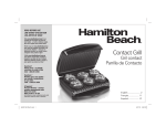
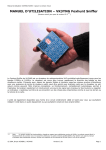
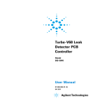
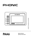
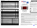
4.30 DEFROST parameters
Description
Range
Default
Defrost time period. It is the period of time between two defrost actions.
1 .. 240 (dtS)
6h
Defrost duration timeout. It is the max duration of each defrost action. If ddt=0 the defrost function is disabled.
0 .. 240 (dtS)
30 m
Defrost time scale (ex tiS). It changes the time scale of dPt and ddt. 0: dPt hours, ddt minutes; 1: dPt minutes, ddt seconds.
0 .. 1
0
Defrost end temperature. Only valid when dead-band mode is activated (Sdb > 0).
During the defrost action, the controller checks the temperature 2. When the evaporator reaches the dEt value, the controller
dEt
-20 .. 100 °C
7 °C
stops the defrost action. From any start of the defrost action, the controller stops the defrost after ddt time, even if
temperature 2 is less than dEt (timeout end).
Defrost type (ex odd). Define the outputs K1 K2 actuation to perform the defrost actions.
When dead-band mode functioning:
dtP
0: switch off K1 and K2; 1: switch off K1, switch on K2; 2: switch on K1 and K2.
0 .. 2
1
When 2-stages mode functioning:
0: switch off K1 and K2; 1: switch off K1, no change K2; 2: no change K1, switch off K2.
Defrost start delay. It is a delay between the time to start of the defrost action and its real beginning (must be dSd < dPt).
dSd
At the power on of the controller, it starts the first defrost action after dPt hours + dSd minutes (and the sucessive starts after 0 .. 120 minutes
0m
dPt). If an external contact activates the defrost action (if Eio=±4), it starts after dSd + Eid minutes.
Delay to switch on the K1 (not K2) after a defrost end (ex Add). After a defrost cycle, the compressor is stopped to assure
dAd
0 .. 120 minutes
0m
dripping of possible water still present in the evaporator.
Displayed during the defrost action (also as per tdi value, see the tdi parameter)
0: probe temperature at the defrost start; 1: the message “dEF”; 2: the SEt / St2 value; 3: the real temperature probe.
ddd
0 .. 3
0
When 0, 1, 2 and dead band mode or 2-stages functioning with a cooling channel showed, the value still shown on the display
until the controller will have reached again the Set Point value.
When dead band functioning by the probe 1 the DC32 checks and regulate the room temperature, by the probe 2, if enabled (Pr2=1), DC32 controls the defrost end. Or, setting
i.e. dEt=100 and tdi=1, by the probe 2 it is possible show a different temperature, measured in a particular room point.
When 2-stages functioning the defrost actions occurs always at fixed period dPt and duration ddt; if probe 2 enabled it will control the output K2 relay.
Rev.: 30-01-2009 Cod.: 82300.0106.0
Param.
dPt
ddt
dtS
- KEYBOARD FUNCTIONS
Installation and
operating instructions
Up
Function
Enter: to activate the programming mode and to view and to confirm the
new values.
Function: 1) to show the Haccp records; 2) pushed for 5 seconds, to
start or stop manually the defrost without waiting dSd, or (see LFc=1) to
switch on/off the controller. The off mode, or stand-by, is stored in
memory; 3) in programming mode, to quit the parameters menu without
saving the new values (escape command); 4) during an alarm event, to
switch off the optional internal buzzer and relay.
Up: 1) ) to display, for a few seconds, the probe 2 temperature and,
pushed twice, the probe 1 snap temperature; 2) during the programming
mode, to scroll the parameters menu and to increase the value of the
selected parameter.
Down: 1) pushed together with the Enter key, for 5 seconds, to lock /
unlock the keyboard; 2) during the programming mode, to scroll the
parameters menu and to decrease the value of the selected code.
4.40 Various parameters
Param.
Eio
Eid
Prt
Pr2
rES
Unt
oF1 oF2
tdi
utd
LFc
PSS
LVS
nAd
Description
Range
External contact digital input operation (ex dio).
Negative value: digital input signal is active if external contact is closed. Positive value: dig. input is active if contact is opened.
0: disabled ; ±1: not allowed; ±2 : door open, switch off the output relay K1 and K2; ±3: St2 is the desired temperature
(instead of SEt, only valid when dead band functioning); ±4: start defrost (for another defrost start command, de-activate and
activate again the ext.contact); ±5: toggle to stand-by mode (the off state is not stored in memory); ±6: external alarm,
switch off all the relays, switch on the optional alarm relay or buzzer.
Ext. contact input delay (ex did). From the activation of the external contact, DC32 waits Eid minutes to start the Eio function.
Probes type. 0: both probe input lines are able to read 10Kohm NTC temperature sensor; 1: not allowed; 2: 990ohm PTC.
Probe 2 analog input enabling. 0: probe 2 disabled; 1: enabled.
Display temperature resolution. 0: the temperature is shown in tenths of degrees; 1: temperature without decimal point.
Temperature unit measurement. 0: Celsius degree; 1: Fahrenheit degree.
(changing Unt value, DC32 doesn’t match any parameter. Rearrange temperature param. values in order to adjust the control)
Temperature probes calibration. To modify the temperature value measured by the probe 1 and by the probe 2.
Temperature displayed. 0: temperature probe 1; 1: temperature probe 2; 2: SEt value.
Pressing the “Up” key it is possible to display for a few seconds the temperature measured by probe 2 and then 1.
Update temperature filter. Different averages are performed to avoid noise spikes on the probes measurements.
0: filter disabled (3 measures displayed per seconds); 10: the temperature average is evaluated on the longest time span.
Long pushing Function configuration.
0: pushing for 5s the “Function” key start/stop defrost; 1: pushing for 5s the “Function” key toggle on/off the DC32 (stand-by).
Password setting. It is possible to set a password to access on the 2nd menu parameter. 0: password request disabled.
Low voltage sensing. In order to improve the functioning, the controller continuously verifies the power supply voltage.
0: function disabled; 1: short voltage drop is not detected (min sensitivity); 10: short voltage drop is detected (max sensitivity).
Slave device number address. It is the address of the controller in a bus network with ModBus-RTU protocol.
0: serial port is disabled. When a key is pushed or in programming mode, DC32 does not always answer to the serial port.
(after having changed this value, the DC32 must be restarted)
Default
Down
-6 .. 6
0 .. 60 minutes
0 .. 3
0 .. 1
0 .. 1
0
0m
0
1
0
0 .. 1
0
-10 .. 10 °C
0 °C
0 .. 2
0
0 .. 10
5
0 .. 1
0
0 .. 999
0
0 .. 10
1
0 .. 247
0
5.00 Troubleshooting
Message
Description, cause
Hit
The measured temperature of probe 1 (only Probe 1) is higher than the (AHi+0,4)
parameter value. If AtP=1, the temperature is higher than (SEt+AHi+0,4).
Lot
The measured temperature of probe 1 is Lower than the (ALo-0,4) parameter value. If
AtP=1, the temperature is lower than (SEt-ALo-0,4).
ALE
Extern alarm. When Eio=±6 and the external contact is active.
PF1
The probe input line 1 is opened/disconnected or short circuited.
The measured temperature is out of the range.
The probe input line 2 is opened/disconnected or short circuited.
The measured temperature is out of the range.
The probe input line 1 + 2 is opened or short circuited.
Memory error. The parameter list could be corrupted. There is no temper./output control.
EEP
Immediately check every parameter value, save the correct value, restart the DC32.
LoV
Low voltage detection on the power supply. Check the voltage value, noises (par. 1.20).
dOP
Door opened. When Eio = ±2 and the external contact is active.
OFF
The controller is going to switch off the outputs and display (stand-by mode).
(*) Note: setting the parameter Pr2=0 will disable the 2nd analog input in DC32, for appliances with 1 probe.
PF2
(*)
PrF
Output
The outputs don’t change.
Switch on the optional relay output or buzzer.
*The controller starts to save the alarm data (haccp).
The outputs don’t change.
Switch on the optional relay output or buzzer.
*The controller starts to save the alarm data (haccp).
All the outputs relay are switched off.
Switch on the optional relay output or buzzer.
The output K1 activation is according the PEc parameter.
K2 output swith off if dead band or 2-stages with 1 probe
functioning .
Switch on the optional relay output or buzzer.
K2 output swith off if 2-stages with 2 probes functioning .
Switch on the optional relay output or buzzer.
See PF1 + PF2 output.
Not predictable.
All the outputs are switched off.
Switch off the K1 and K2 outputs relay.
All the output relays are switched off.
Enter
DC32 II Series
Electronic dead-band
and
2-stages controllers
1 2
Light on
Flashing
at least a compressor is running;
waiting for a time delay to switch on compressor.
Light on
Flashing
at least a heater is switched on;
waiting for a time delay to switch on heater.
Light on
Flashing
output relay channel 1, 2 switched on;
waiting for a time delay to switch on the output 1, 2.
(the number 1 and 2 are working only during 2-stages mode functioning)
Light on
Flashing
defrost action is running;
high temper. probe 2 (only when dead band mode).
The upper left point is flashing in programming mode and is lit on if an external
contact is active (digital input) or when the DC32 is switched off in stand-by mode.
The numbers 1 & 2 are NOT referred to the probe temperature showed.
1.00
GENERAL DESCRIPTION AND INSTALLATION NOTICE
The DC32 models are controllers designed to control refrigeration/heating appliances, by dead-band or 2 indipendent stages functions.
When dead-band mode it checks the main temperature probe and manages the cooling (K#1 output) and heating (K#2 output) relay in
automatic way, to regulate the room temperature around one desired SEt point value.
Whereas the 2-stages control mode is suitable to select heating or cooling mode for each of the two output relays, with different SEt point
temperature values. Enabling the second probe, it will achieve two indipendent control channels, like having two separate thermostats.
The DC32 has two analog inputs for temperature probes Ptc and Ntc type, a digital input for an external contact, two power relay outputs and,
optionally an alarm relay or buzzer. It can perform defrost actions with varied functions, verify temperature alarm conditions and store the last 3
events (Haccp feature). Through the TTL port, an external master device can exchange data, read and write DC32 registers.
1.10 Installation notice
The installation must be done only by specialized personnel in according to the rules in force in the country where the controllers are used. The
instrument is conceived for controlling and regulation, not for safety function. It must be installed in a place protected from extreme vibrations,
impact, water, corrosive gases, and where temperature and moisture do not exceed the maximum rating levels indicated in the specifications.
The same directions are valid for the probe installation. The probe is not waterproof, it should be placed with its head upward, so that drops
would not penetrate into the bulb and damage the sensor. Maintain the length of the electrical wires as short as possible in order to keep the
noise picked by them at low level; otherwise a shielded wire will be needed, and the shield will be connected to the ground.
1.20 ELECTRICAL WIRING
We recommend to protect the power supply of the controller from electrical noise, spikes and especially from voltage surges and drops:
-separate the power supply of the loads (compressor, heaters, fans) from the power supply of the controller. This alleviates problems related to
voltage dips that can arise during the switch-on of the loads, that may disturb the controller’s microprocessor causing unexpected resets.
-the cables of the probes and the ones of the controller supply or the loads must be separated, to reduce spikes and noise on the sensor. This
improves the stability of the reading and it also makes the commutation of the device more accurate.
1.30 CRITICAL ENVIRONMENT
For applications in heavy industrial environment these rules should be followed.
- After having identified the source of noise spikes, it is recommended to apply a line filter to the source in question of the type specifically
designed to solve EMC (Electromagnetic compatibility) related problems. Sometimes it may be sufficient an RC type filter, also called
«snubber» , connected in parallel to the external relay coils, or circuit breakers.
- An independent power supply should be used to power the device in extreme conditions.
ATEX Industries srl
33078 S. Vito al Tagliamento – PN
ATEX reserves the right to make changes without further notice to any products herein to improve reliability, function
Italy
or design. ATEX does not assume any responsibility for any improper use or application of any product or circuit
Tel.: +39 0434 85183 r.a.
described herein. ATEX products are not designed, intended, or authorized to be use as components in systems or
www.atex.it - www.betaelectronics.it
applications intended to support or sustain life, or for any other application in which the failure of the ATEX product
could create a situation where personal injury or death may occur.
K3
K2
K1
or
if Sdb = 0 2 Indipendent Stages
Output K2 on (heater)
Output K1 on (compressor)
The probe 2 can be used to
control the defrost cycle ends or
to shows a different temperature.
K1 and K2 off
when Sdb > 0
DEAD BAND CONTROL
is activated
TTL port
DC 32
K1 = SPST 12A 250Vac max resistive
K2 = SPDT 8A 250Vac max resistive
K3 = SPST 5A 250Vac max resistive
SEt-Sdb
2
SEt-Sdb-SH2
2
SH2
SEt
SEt+Sdb
2
Sdb
SEt+Sdb+SHY
2
SHY
temperature
probe 1
St2
St2
1 2
digital input
alarm
Act1
Figure 2:
2 INDIPENDENT STAGES
WITH 1 PROBE
if Sdb=0, Pr2=0
Example with Act=0 & Ac2=0
63,5
6,8
34,5
Frontal dimensions: 34.5 x 76.5 mm
Mounting hole dim.: 29 x 71 mm
( 34,5 x 76 mm )
TTL serial
port
SEt
3.20 Menu Level 2 - Adjust all the other OPERATING PARAMETERS
1) Press the Enter key “↵” and hold it for 6 seconds. The upper point will flash to indicate programming mode entering. If no password is set
(PSS=0), the code of the first variable SHy will appear, go to point 3. If password is set, will appear “PAS” request;
2) (password request) Press and release the Enter key “↵”, “0” will be shown; press “5” to enter the right password value and then press and
release the Enter key to confirm it. If the value entered does not match the stored password (PSS), the controller exits the programming mode;
3) (SHy showed) press “5” or “6” to scroll all the parameter codes;
4) While a code is displayed press and release the Enter key “↵” to view its content, adjust it by pressing “5” or “6”;
5) Press and release “↵” to confirm the data, after 15sec. the DC32 will quit the programming mode and the data will be stored in the memory.
WARNING:
- the instrument must not be reset before leaving the programming mode, otherwise the new setting will be lost;
- if the “Function” key is pressed during the programming mode, the user will exit the progr. mode without saving, DC32 will loose the new setting;
- the controller authomatically interrupts any setting operation if any push-button isn’t pressed for at least 15 seconds and store the current data;
- after having modified any parameter the controller must be restarted (unplug and plug again) .
3.30 Keyboard locking
Press and hold both the Enter key “↵” + the Down key “6” for 6 second, in order to lock and unlock the keyboard (the upper-left point will flash).
If the controller shows “Pof” it means the keyboard is locked, if it shows “Pon” the keyboard is unlocked.
When the keyboard is locked it is possible to view any parameters value but not to change them.
3.40 How to show the stored alarm temperatures (Haccp feature)
The DC32 stores the last 3 temperature alarm events: the temperature of probe 1 has been lower than ALo or higher than AHi.
- when the controller is showing the temperature (i.e. not in programming mode), press and release the “Function” key;
- it will show “HcP” (Haccp) and, if any alarm data are stored, it will show “AL1”, min/max temperature reached and for how long (minutes) the
temperature 1 was over ALo or AHi, then “AL2”, min/max alarm … . AL1 is referred to the most recent event. AL3 is the oldest.
When the DC32 is showing the Haccp data, pressing the “Function” key for 5 seconds will erase the alarm data stored (it will show “---“).
The controller will show only data for alarms of events which have come back to normal. If an alarm is running, it could be ended decreasing the ALo
or increasing the AHi value. At the end of an alarm the DC32 stores the Haccp data in its memory.
During the defrost actions there is no alarm recording. DC32 doesn’t have a battery inside, if power fails occurs it does not check/record any data.
Changing the temperature measure unit (“unt” param.), the logged temperatures / parameters values reflect unit set in the past (not convert).
SEt+SHY
2 INDIPENDENT STAGES
WITH 2 PROBES
if Sdb=0, Pr2=1
K1 on
K1 off
Example with Act=0 & Ac2=0
St2+SH2
K2 on
K2 off
temperature probe 2
SEt
SEt+SHY
K1 on
K1 off
temperature probe 1
St2
SHy,
SH2
REAR BOX
3.10 Menu Level 1 - Adjust the main (SEt) and secondary SET POINT (desired temperature value)
1) Press and release the Enter key “↵”, SEt is displayed. The upper point will flash to indicate programming mode entering. To view/change St2,
press “5” or “6” to move to St2 (secondary Set Point);
2) Press and release “↵” to view the Set Point value, adjust it by using “5” or “6” (it is only possible values inside the SLo and SHi range);
3) Press and release “↵” to confirm the data, after 15sec. the DC32 will leave programming mode and the new data will be stored in the memory.
Figure 3:
4.10 CONTROL OUTPUTS K1 K2 Parameters
Sdb
3.00 SETTING THE DC32
K2 on
temperature probe 1
Param.
SEt
( 63,5 x 70 mm )
St2+SH2
K2 off
temperature
probes
28,5
- connections terminal block with screw for max 2.5mm2 gauge wire;
- operating temperature: –10 … +60 °C;
- storage temperature: –25 … +70 °C;
- storage humidity: 30 … 90 % r.H., non condensing;
- plastic casing (PC+ABS rear box, PC frontal panel);
- frontal panel IP65, if appropriate mounting gasket;
- max temperature of the switch head: 60 °C;
- pollution degree: 2;
- rated impulse voltage: 2.5 KV;
- PTI of insulating material: 175 (circuit board 250);
- class of protection against electric shock: II (for correct install.);
- class of protection against voltage sourges: category II;
- type of disconnection: 1.B micro disconnection (relay);
- software class: A.
4.00 TWO OPERATING WAYS: if Sdb > 0 Dead Band
Figure 1:
Act2
POWER : 230 Vac ±10% 50/60 Hz (3VA max);
SUPPLY or 115 Vac ±10% 50/60 Hz (3VA max);
or 12 Vac/dc ±10% (150mA max) (use only SELV power s.);
or 9..24 Vac/dc (use only SELV power supply).
INPUTS: 2 Ntc/Ptc sensors, 1 Digital-In external contact (max 1mA);
Probes types: Ntc standard 10Kohm@25°C Beta=3435-25/85;
Ptc 990ohm@25°C KTY81(2)-121.
OUTPUTS: 1 spst relay 250Vac 12A max resistive (K1 channel 1 relay);
1 spdt relay 250Vac 8A max resistive (K2 channel 2 relay);
1 spst relay 250Vac 5A max resistive (optional, alarm relay);
(the max const. current in the common terminal #1 is 12A)
SERIAL PORT: TTL level, ModBus protocol, RTU type, 9600 baud,
8bit char, even parity, 1 bit stop;
DISPLAY: 3 digit LED, 14 mm height, high intensity red;
MEASURING RANGE: -50 … +150 °C / -50 ... +302 °F (if Ptc);
- resolution: 0.1 °C / 0.1 °F (within –19.9 .. +99.9);
- accuracy @25°C: ±0.5 °C + 1 digit;
Typical terminal connections (See the label on top of the instrument
for the right power supply diagram connection).
constant
max 12A
2.00 TECHNICAL SPECIFICATIONS
SLo
SHi
Act, Ac2
rA1, rA2
ro1, ro2
PEc
PE1
PE0
Descrizione
Set point: it is the desired temperature, checked by the probe 1.
Secondary set point.
When dead band operating mode, it is the value for the energy saving function, activated by the digital input.
When 2 indipendent stages operating mode (Sdb=0), it is the desired temperature for the channel 2, to drive the K2 relay.
Set point Hysteresis (ex HyS, Hy2). Delta temperature value to avoid regulating oscillations. See figures 1, 2 and 3.
(Example: when Act=0, the compressor switches off at SEt and switches on at SEt+SHy value).
Setting Sdb=0 the “two indipendent stages” operating mode is activated (figures 2 and 3), with 1 or 2 probes controlled.
output
K1
Default
5 °C
SLo .. SHi °C
8 °C
0.1 .. 20 °C
2 °C
0.0 ,
Setting Sdb (ex dEb) greater than 0 the “dead band” operating mode is activated (see figure 1). Sdb is the gap of temperature
inside which there are no one control output active. When dead band operating mode is active, the K1 output relay is to drive a
compressor and the K2 relay to drive a heater. The Act and Ac2 parameters disappear from the menu list.
Low Set Point limit (ex LoS). It is the min value of SEt & St2 parameter range. The user cannot select a value lower than SLo.
High Set Point limit (ex HiS). It is the max value of SEt & St2 parameter range. The user cannot select a value higher than SHi.
Only valid for 2 indipendent stages functioning – when Sdb=0
Act is the action mode of the K1 output relay; direct for cooling systems, inverse for heating control.
0: direct action (refrigeration). As temperature rises over (Set+SHy), it switches on the K1 output (for a compressor);
1: inverse action (heating). As the temperature falls below (Set-SHy), DC32 switches on the K1 output (for a heater).
The same for Ac2 and the output K2 relay (indipendent by K1 mode). See figures 2 and 3.
Anticycle retard (ex Acy). rA1: when the K1 output is switched-off, the controller waits at least rA1 minutes to switch on again
the relay. It is also the delay for the first activation of the relay at power on. The same for the rA2 and K2 relay output.
Retard to switch on the output relay. ro1 is the delay to switch on the K1 relay from the request to activate it.
When the probe 1 temperature requires to activate the K1 output, the software starts to waiting ro1 minutes before switching
on the output relay. This delay is not considered when PF1. After defrost, compressor waits also ro1 (see also dAd).
The same for the ro2 and K2 relay output.
Probe 1 error, output K1 mode (ex CPF) – only for the K1, not for the K2 output. If there is a probe 1 fault (see par. 5.00) the
DC32 starts to manage the K1 output relay by time and shows PF1 on display.
0: K1 relay always off; 1: K1 relay always on; 2: K1 relay on for PE1 minutes and off for PE0 minutes.
Probe 1 error, output K1 on (ex Con). The time to switch on the K1 relay when there is a PF1 error (if PEc=2).
Probe 1 error, output K1 off (ex Cof). The time to switch off the K1 relay when there is a PF1 error (if PEc=2).
WARNING: during the installation, take
care to set proper rA1 rA2 value to avoid
compressor or relay faults.
Limiti
SLo .. SHi °C
2 °C
0.1 .. 20 °C
-50 .. SHi °C
SLo .. 150 °C
-40 °C
110 °C
0 .. 1
Not
selectables,
infact
Sdb>0.
0 .. 20 minutes
0m
0 .. 20 minutes
0m
0 .. 2
2
0 .. 45 minutes
0 .. 45 minutes
15 m
30 m
on
ro1
rA1
rA1
ro1
rA1
off
if ro1=0
if ro1>0
time
4.20 ALARM parameters
The temperature alarm events are always linked to the probe 1. The alarm hysteresis is 0,4 °C fixed.
Param.
code
AtP
ALo
AHi
Adi
ALd
AdF
Ad0
Ad1
Description
Alarm type values.
0: ALo, AHi are absolute temperature values;
1: ALo, AHi are temperature values relating to the SEt value (also when St2 is activated).
Low temperature threshold alarm (ex LoA). If the temperature goes below this value (ALo-0,4), the controller activates an
alarm signal on the display and starts recording the minimum temperature and the duration of the alarm (Haccp).
If present, switch on the alarm relay or buzzer.
High temperature threshold alarm (ex HiA). If the temperature goes up over this limit value (AHi+0,4), the controller activates
an alarm signal on the display and starts recording the max temperature and the duration of the alarm signal.
If present, switch on the alarm relay or buzzer.
Alarm delay at the power on. The DC32 does not check any temperature alarm for Adi hours from the power on.
Alarm delay on running time. The temperature must be in the alarm range for ALd minutes to switch on the alarm signal.
Alarm delay after defrost. After the end of any defrost, the DC32 waits AdF minutes before checking any temperature alarm.
Alarm delay after de-activation of the external contact (digital input).
Alarm delay from the activation of the external contact. The delay count starts immediately without waiting Eid.
Note: The alarm signal management is disabled during the defrost actions (no star, nor stop alarm).
Range
Default
0 .. 1
0
AtP=0, –50..(AHi-1)
AtP=1, -50 .. –0.5°C
-40 °C
AtP=0, (ALo+1)..150
AtP=1, 0.5 .. 150°C
110 °C
0 .. 10 hours
0 .. 120 minutes
0 .. 180 minutes
0 .. 240 minutes
0 .. 120 minutes
0h
0m
0m
0m
0m