1
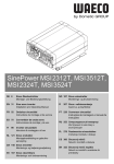
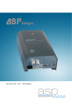
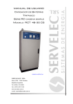
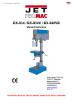
INSTALLATION AND OPERATING INSTRUCTIONS FOR
EMERGENCY MODULES USING FLUORESCENT LAMPS
These instructions contain important information on safety and operation. They should be read carefully and retained at the
installation for future reference. The re-engineering of existing mains luminaries by the installation of this unit causes the luminaire to
fall within the scope of the CE Marking legislation and we strongly advise suitable testing is done to ensure continued compliance with
the CE Marking Directive, Electro-Magnetic Compatibility Directive (2004/108/EC), Low Voltage Directive (2006/95/EC) and
Construction Products Directive (89/106/EEC) to satisfy legal requirements.
GENERAL DESCRIPTION
This module is for intermittent use and can be used in non-maintained or maintained (with mains control gear) modes of operation with a single
4-pin fluorescent lamp. The battery charger circuit incorporates a mains transformer compliant with the relevant clauses of IEC61558,
providing basic installation, a self -resetting over temperature device, high voltage inverter circuit and a battery connected and charging
indicator. Suffix ‘P’ versions include a battery deep discharge protection circuit. The charger is designed to provide full duration after 24
hours charge period in accordance with EN61347-2-7. Typical wiring diagrams are included in this leaflet and all connections should be made
in accordance with these diagrams.
INSTALLATION
Installation of the module into the luminaire should be carried out by competent persons and in accordance with information given in this
instruction leaflet and any relevant national wiring regulations. The module is protected against battery reversal but care should be taken
during installation to ensure correct connections to all module terminals before any power source is connected. We advise that the battery
current is measured in emergency discharge mode by inserting a low impedance ammeter into the battery circuit, then checking to ensure that
the discharge current, which for standard modules is in the range 0.9A to 1.25A when the lamp has fully struck. If values outside this range are
recorded please contact us before proceeding further and if in doubt, please consult a suitably qualified person.
ENVIRONMENT
This module is rated for use in normal indoor conditions inside a luminaire or remote box within the ambient temperature range 0ºC to 50ºC. If
operation in damp, dusty or corrosive environments is required, the module should be mounted in an enclosure suitable for the environment in
which it is to operate, taking into account any temperature limits introduced by the enclosure material. Unless otherwise stated, this module is
designed for direct connection to a permanent standard mains supply without any intervening control device other than a mechanical switch or
fuse.
PRE-INSTALLATION
Before commencing installation ensure that the ratings shown on the module are compatible with the mains supply, lamp and battery pack to
be used. The electricity supply and the battery pack should be disconnected before work of any kind is undertaken, including installation,
maintenance, cleaning and lamp replacement or fuse replacement. Remember that the output terminals of the module may be live, even when
the mains supply is not present. Additional wiring used in the installation of the module should have insulation suitable for be 105º C or
higher temperature operation and be single-conductor type. Maximum Conductor size 1.5mm²
INSTALLATION INSTRUCTIONS
(a) To ensure adequate safety standards are complied with, the luminaire should be insulation and earth continuity tested prior to
installation but ensure the emergency lighting module and any electronic ballasts are disconnected prior to this testing.
(b)
The module should be securely mounted and must be earthed using appropriately sized screws, nuts and washers. When planning the
internal layout of the luminaire particular attention should be paid to the maximum operating temperatures of the module and battery
pack. We recommend that temperature tests be performed in accordance with RN60598.2.22 on the complete luminaire before
finalizing the layout.
(c)
Connect the lamp to the module and if applicable control gear as shown in the relevant diagram. The two connections of one lamp
cathode to module terminals 3 and 4 and the other two lamp cathode connections to module terminals 5 and 6. These are the only lamp
connections needed for non-maintained operation. All internal wiring should be single-core high temperature type with at least a105°C
Rating and a minimum conductor size of 0.8mm with a minimum insulation thickness of 0.6mm and loosely grouped but separate from
other wiring. For operation in maintained mode additional mains control gear is required, which should be connected to module
terminals 1, 2 and 7, 8, with typical circuits being shown in this leaflet.
We recommend that old mains luminaires are not converted but where this is unavoidable, all internal wiring and lamp holders should
be replaced
(d)
The charge indicator LED should be mounted where it will be visible without the need to remove covers or where this is not possible,
adjacent to the luminaire. A 6.35mm (1/4”) mounting hole is required for the fixing bezel where required.
(e)
The case of the module must be earthed and after making all wiring connections connect the battery to the module
(f)
Connect the permanent mains supply to the module:
BROWN – LIVE
BLUE – NEUTRAL
REMOTE MOUNTING
Remote mounting in a suitable enclosure is possible within the maximum allowable distance of 1 metre from the luminaire allowable in
EN60598.2.22. The interconnecting loom must be kept as short as practical, as a high frequency waveform is present in emergency, which
will produce EMC emissions and energy absorption. The interconnecting wiring should be via loosely grouped, single-core-conductors
routed through fire retardant non-metallic conduit.
COMMISSIONING INSTRUCTIONS
Connect the permanent mains supply and check the charge indicator is illuminated. If the module is being used in the non-maintained mode,
the fluorescent lamp should not be illuminated. If the module is being used in a maintained mode turn on the switched mains supply and the
fluorescent lamp should illuminate fully via the mains control gear. A minimum battery charge period of 24-hours should be allowed before
testing the module for its rated duration. Maximum recommended battery storage period is 12-months and if the batteries have been left in a
discharged state for a long period, multiple charge and discharge cycles may be required before they recover their full capacity.
LAMPS AND BATTERY DISPOSAL
Use only lamps and batteries of the recommended type and rating for the module should be used. Lamp disposal should be carried out in
accordance with the instructions of the lamp manufacturer or your lamp supplier. Disposal of lamps and batteries is subject to the WEEE
Directive and some local authorities have additional specific requirements and they should be consulted for specific guidance. Failed lamps
and batteries should be replaced promptly to avoid damage to the module.
MODULES WITH DEEP DISCHARGE PROTECTION
Leaving a battery connected to an uncommissioned module may cause premature failure of the battery and lamp. This type of neglect is
excluded in our guarantee. Modules with DDP will not operate until triggered by applying the permanent mains supply. When the permanent
mains supply is removed, the battery will discharge into the inverter and the lamp will illuminate until the battery deep discharge protection
turns the module off. The permanent mains supply may then have to be connected to the module for a period of about an hour to give a small
recharge to the battery before another functional test can be performed.
TYPICAL CIRCUITS – if any doubts exist regarding wiring, please contact our Technical Department before connecting or powering up the
module. On modules with the additional electronic ballast control relay, the switched supply to the electronic ballast must be wired to Live
In, on the module with the module Live Out going to the electronic ballast.
MAINTAINED SWITCH START CIRCUIT
1
2
3
4
5
6
7
8
MODULE
CHOKE
L
S
PFC
N
PINS 3, 4, AND 5, 6 ARE THE HOT WIRES IN EMERGENCY MODE AND NEED TO BE KEPT AS SHORT AS PRACTICAL
NON-MAINTAINED CIRCUIT
MODULE
1
2
3
4
5
6
7
8
TYPICAL CONNECTION DETAILS FOR ELECTRONIC BALLASTS FOR TWIN LAMP CIRCUIT (ONE LAMP ILLUMINATED IN
EMERGENCY MODE)
MODULE
1
2
3
4
5
6
7
8
Ballast lamp one cathode 1 connections
Ballast lamp one cathode 2 connections
This module can be used with most electronic ballasts by substituting the above for one of the lamp connections to the ballast. Some ballasts
use a common connection for the lamp cathodes (see below).
TWIN
BALLAST
1
2
3
4
5
6
7
In this case the module connections must be on the lamp side of the joint as shown by the X in the diagram. Failure to observe this precaution may
result
in damage
to the module.
When using
two single
lamp luminaires
end-to-end always use the lamp closest to the module as the emergency lamp.
HIGH
FREQUENCY
SINGLE
LAMP
MAINTAINED
CIRCUIT
PIN NUMBERS MAY VARY ON
DIFFERENT MANUFACTURERS
BALLASTS EVEN THOUGH THE
WIRING CONFIGURATION MAY
BE THE SAME. PLEASE REFER
TO THE DIAGRAM ON THE
BALLAST LABEL.
MODULE
1
2
3
4
5
6
7
8
1
2
3
STANDARD 4-PIN
SINGLE LAMP
ELECTRONIC
BALLAST
4
PINS 3,4 AND 5,6 ARE HOT WIRES IN THE EMERGENCY MODE
DISPOSAL
The disposal of large quantities of electrical equipment (EEE) is subject to European, National and Local Authority regulations
(WEEE).
Products displaying the ‘wheelie bin’
symbol indicate the product should not be disposed of in the normal waste stream.
STORAGE CONDITIONS
This module should be stored in dry conditions, with temperature not exceeding the limits – 10°C to 60°C.
ROUTINE TESTING
Testing should be carried out in accordance with recommendations of EN50172 the main points of which are detailed below and records of
testing kept up to date and available for inspection.:
Once a day
Visually inspect the charge indicator is illuminated.
Once a month
Each unit should be energised from its battery by simulation of a failure at the normal supply for a period sufficient to inspect each lamp is
illuminated. At the end of the test the supply should be restored and the charge indicator inspected.
Yearly
Each unit should be as per monthly test but for its rated duration. The date of the test and its results shall be recorded.
To assist with this testing, a sample test record is shown in this leaflet.
If the charge indicator is unlit it signifies a fault and to increase the probability of a fault being reported between monthly tests, it is desirable
that all staff are aware of the purpose of the charge indicator and the person responsible for the emergency lighting system on the site.
.
PERFORMANCE AND WARRANTY
In place of any other conditions and warranties, whether imposed by statute or implied by Common Law we undertake as follows: (A) We will repair or, if necessary, replace free of charge any material or work found to be defective in our ‘Emergency Lighting Control
Gear’ and bought to our attention within 12 months from the date of supply.
This warranty will only be valid if the module has been used with the supply voltage, within the stated operating temperature range,
correctly sized battery pack and lamp and has remained unmodified and used in accordance with this instruction leaflet and our
literature.
(B) The battery packs are guaranteed for 12 months but are expected to have a life of at least 4 years if used within the specified
temperature limits.
(C) We shall not be liable for any consequential loss or damage caused directly or indirectly by any defect or otherwise.
The company will accept no responsibility for any modified modules, or for damage caused as a result of any modification. All details are
given for guidance only and do not constitute a contract. We reserve the right to change the characteristics of products without notice.
TECHNICAL DETAILS
SPECIFICATION
Mains Supply:
As label ± 6% 50/60 Hz (Modules for other
Supplies available).
Maximum current consumption 80mA (at 240V)
43mm
Length 154mm
Fixing Centres 144mm
Panel cut out for charge
Indicator
6.35 (¼")
Battery Charger:
Constant current. 24-hour recharge.
3-Hour Modules = 0.31A nominal.
1-Hour Modules = 0.17A nominal.
35mm
Dia
Discharge Current:
1.0A nominal for 1, 2 and 3-hour modules.
PLATE MOUNTED
BATTERY PACKS
Inverter Operating Frequency:
25-60Khz.
65
40
40
Permitted Operating Temperature:
(Centre side of module case)
Minimum 0°C.
Maximum 70°C.
DUAL IN-LINE BATTERY PACK
Mains Connections:
Terminal block, 1.5mm² max.
75mm
Lamp/Mains Gear Connections:
8-way terminal block, 1.5mm² max.
40mm
36mm
Battery Connections:
Terminal block, 1.5mm² max.
40mm
Indicator Connections:
Terminal block, 1.5mm² max.
IN-LINE BATTERY PACK
Battery Packs:
High temperature nickel cadmium cells using
2Ah for 1-hour modules and 4Ah for 3-hour
modules. Maximum temperature 50°C.
Certain units are suitable for use with both
Ni-CAD and Ni-MH 4Ah high-temperature cells.
Maximum cell temperature 50°C. Refer to the catalogue.
TEST RECORD
Type……………………………
TEST
1st YEAR
1 functional
2 functional
3 functional
4 functional
5 functional
6 functional
7 functional
8 functional
9 functional
10 functional
11 functional
12 full duration
The test engineer should sign and date each test.
MONTH
Location……………………………
2ND YEAR
3RD YEAR
ORIGINAL
4TH YEAR
5TH YEAR
28-665/10