1
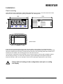
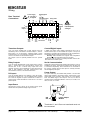
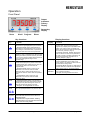
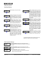
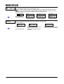
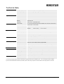
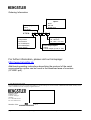
Operating Instructions tico 735 – DC Volts/Amps Indicator
Introduction
Your Hengstler tico 735 for DC Volts and Amps is one model in a family of 1/8 DIN units which offers
breakthrough display technology as well as easy-to-program single-line parameters.
Designed to provide instant visual feedback regarding an application’s key input value, the tico 735 not
only has a 18 mm high LED display, but also the ability to change display colour based on process
status (programmable parameter in Operation Mode). Easy programming is made possible via a help
function and a secondary legend display.
This manual will guide you through the installation and wiring of your tico 735 unit with information on
proper panel mounting and rear terminal layout and wiring instructions. In addition, the instrument’s
operation, programming and configuration modes are thoroughly explained. The operation mode
provides day to day operation and allows editing of preset values. The Program Mode enables the
configuration of various parameters prior to initial operation. These
parameters include those for basic configuration as well as other
settable features which will enhance the functionality and usability
of the device. The Configuration Mode allows selection of how
outputs and special functions are utilized.
This manual also provides information on the tico 735 DC
Indicator’s product specifications and ordering information.
Please read the safety information carefully prior to
the installation of the unit!
Features
Awesome 18 mm high digit LED display
Programmable colour change display based on an event
High and Low alarm outputs
Inputs from 0-1 V to 0-600V, 0-1 mA to 0-2 A
Standard outputs: two NPN transistors & one relay (optional 2nd relay)
250 ms sample time at 0.1% accuracy
Optional RS-485 plug in card
Index
Safety Instructions ...................................................................................................................... 2
Installation .................................................................................................................................. 3
Operation.................................................................................................................................... 5
Program Mode............................................................................................................................ 9
Configuration Mode .................................................................................................................. 12
Technical Data.......................................................................................................................... 15
2 735 150, Rev. 1120600eli
Operating Instructions tico 735 – DC Volts/Amps
page 1 / 16
Safety Instructions
This symbol indicates passages in the text which you have to pay special attention
to so as to guarantee proper use and preclude any risk.
The range of applications for this product are industrial processes and controls, where the
overvoltages applied to the product at the connection terminals are limited to values of the
overvoltage category II.
This device is made and tested according to the valid standards of technics and has left the
factory in a perfect safety state. To keep this state and secure operation without danger, the
user has to observe the saftety and warning hints, contained in this operation manual.
Assembling and mounting of electrical divices are restricted to be done by skilled electricians!
Skilled electrician is, who can judge the tasks deputed to him and foresee possible dangers,
due to his special education, knowledge and experience and consciousness of the pertinent
standards.
Mount devices are only allowed to be operated when mounted.
Terminals which are not used (NC) must not be connected.
Finger protection at connection part of mount devices is to be secured when mounting!
While mounting the device, it must be secured that the requirements, which are asked for the
device in the pertaining standards for safety, are not affected in a negative way, so reducing the
safety of this mount device.
Mounting and assembling of device needs observation of the specifications of the local Energy
Suppliers.
Before switching on, make sure that the power and control voltages are not exceeding the
values in accordance with the technical data.
If it is to be assumed that operation without danger is not further possible, the device must be
put out of operation and secured from unintentional operation! It must be assumed that an
operation without danger is not further possible,
if the device shows damage
if the device stops functioning
after a longer stocking period under unfavourable conditions
after heavy strain during transportation.
If by a failure or a malfunction of the device, endangering of men or animals or damaging of
facilities are possible, this must be avoided by additional safety measures (end switches,
protection devices and etc.).
Before opening any cover, the device must be switched voltagefree.
Hengstler Indicators are intended for industrial applications.
The mounting environment and nearby cabling have an important influence on the EMC (noise
radiation and noise immunity) of the indicator . When putting into operation, the EMC of the
whole installation (unit) has to be secured. In particular, the relay outputs are to be protected
from high noise radiation by suitable wiring.
page 2 / 16
Operating Instructions tico 735 – DC Volts/Amps
2 735 151, Rev. 1120600eli
Installation
Panel mounting
The instrument can be mounted in a panel with a thickness of up to 12 mm. The cutout should be made
based on the recommended panel opening illustrated in the drawing below.
96
100
48
tico 735
PGM
RST
45 + 0.5
92 + 0.5
panel cutout
Insert the unit in the panel through the cutout. Ensure that the panel gasket is not distorted and the
instrument is positioned squarely against the panel. Slide the mounting clamp into place on the instrument
and push it forward until it is firmly in contact with the rear face of the mounting panel and the tabs on the
bracket arm are seated in the mounting grooves on the side of the unit.
The electronic components of the instrument can be removed from the housing after installation without
disconnecting the wiring. To remove the components, grip the side edges of the panel and pull the
instrument forward. Take note of orientation of the unit for subsequent replacement in the housing.
Please finish all settings in the configuration mode prior to scaling
the display.
2 735 150, Rev. 1120600eli
Operating Instructions tico 735 – DC Volts/Amps
page 3 / 16
Wiring
Power Supply
90 - 240 VAC or
22 - 50 VAC/DC
~
~
Rear Terminal
Connections
Digital Input
+
Relay OUT1
RS 485 Comm.
B
0V
A
NC
13 14 15 16 17 18 19 20 21
10
24
8
7
6
4
5
+
Aux. Power
A-
OUT2
NPN
9
3
2
1
mV / V mA -
23
V+
11
mV +
A / mA +
22
OUT1
NPN
-
NC
12
0V
+
Linear
Output
Relay
OUT2
Danger!
Hazardeous
voltage!
Transistor Outputs
Control/Digital Inputs
Your unit comes standard with 2 NPN outputs which are
activated by each of the alarms. Transistor Output 1, which is
tied to Alarm 1, is on Terminal #7. Transistor Output 2, which
is tied to Alarm 2, is on Terminal #9. Terminal #8 serves as the
common connection for both transistor outputs.
The outputs 7,8,9 are optically isolated from the process
inputs.
A digital input board, which utilized Terminal #16 & #17 as a
contact closure input, can be installed as an option. The input is
activated by connecting the Terminals and can be programmed in
Configuration Mode to perform the followin function:
Security: When acitvated, the Program and Configuration
Modes will not be accessible from the front panel.
Please note that this option is mutually exclusive with the RS485 serial communication option.
Relay Outputs
Serial Communication
Your unit comes standard with a relay output which is tied to
Alarm 1. Terminal #19 is NC, Terminal #20 is common, and
Terminal #21 is NO. A second relay output tied to the
operation of Alarm 2 can be added as an option at the time of
order or later installed in the field. Terminal #22 is NC,
Terminal #23 is common, and Terminal #24 is NO.
An RS-485 communication board, utilizing ASCII protocol, can be
installed as an option. Terminals #16 and #17 serve as the B and
A connections respectively, while Terminal #18 is connected as
the common. Please note that this option is mutually exclusive
with the Digital Inputs option.
DC Inputs
Your unit accepts Millivolt, Volt, milliamp or amp DC ranges.
Terminal #1 is used for mV, V or mA negative inputs. Terminal
#4 is used for negative A inputs. Terminal #2 is used for V
positive inputs, while Terminal #3 is used for mV. mA and A
positive inputs.
Linear Output
An option board may be installed that provides a 10 Bit linear
output signal relative to the Process Value. Terminal #12 is the
positive side of the connection, and Terminal ‘10 is the negative
side. The default range of the output is 4-20 mA, but can be
changed via the Configuration Mode to 0-20 mA, 0-10 VDC, 2-10
VDC, 0-5 VDC, or 1-5 VDC
Input Power
Terminal #13 and #14 serve as the powerr supply inputs.
Please watch the specified voltage range of the unit.
mA
mV, V
Linear Output
Module
Terminals 11 and 15 are not used and must not
be connected.
page 4 / 16
Operating Instructions tico 735 – DC Volts/Amps
2 735 151, Rev. 1120600eli
Operation
Front Panel
Output
Indicators
Primary
Display
Secondary
Display
Down
Scroll
Program
Reset
Display functions
Key functions
Key
Function
Display
Function
Down
In Operation Mode: Used in Edit Operation to
Primary
In Operation Mode: Default display is the
decrement the digit highlighted by the Scroll Key,
if the setting is a numerical value, or present the
next in the series of choices for that parameter
Process value. Can be scrolled using the
program key to display other Operations Mode
values. If the „Help“ function is enabled, this
display will first show the parameter description
for 3 seconds ( example - page 7).
Scroll
In All Modes: Moves the unit into Edit
In Program & Config. Modes: Displays the
Operation, which is indicated by the left most digit
flashing. Successive presses of the key are used
to move to the digit to be edited. Wrap around will
occur from least significant digit to most
significant digit.
Program
In Operation Mode: Used to move between the
decrement the digit highlighted by the Scroll Key
In Program Mode: Used in Edit Operation to
value or selection for the current parameter. If
the „Help“ function is enabled, this display will
first show the parameter description for 3
seconds (example - page 7).
Secondary
process value display & the presets and to enter
an edited preset value. Holding the key down for
3 seconds will cause the unit to enter the
Program Mode.
In Program Mode: Used to move from one
parameter to the next and enter the edited
parameter values. Holding the key down for 3
seconds will cause the unit to return to Operation
Mode.
Output
indicators
In Operation Mode: Provides an alpha or
numeric indentification of the value on the
primary display. This display is blank when the
Process Value is being shown.
In Program Mode: Provides a 1 digit alpha or
numeric character to indicate which parameter
value is being shown on the primary display.
In Operation Mode: Illuminates when Output 1
and / or Output 2 is active.
In Program & Config. Modes: No function
In Config.Mode: Used to move from one
parameter to the next and enter the edited
parameter values.
Reset
Down &
Scroll
Down &
Program
In Operation Mode: Resets a latched alarm if
pressed while the process value is being viewed.
Pressing this key while viewing the max or min
value will cause those values to be reset.
In Program & Config.Mode: No function
In All Modes: Will abort an Edit Operation and
return the preset/parameter to its previous value.
In Config. Mode: Holding down both keys for
3 seconds will cause the unit to return to
Operation Mode.
In Operation & Program Modes: Holding
down both keys for 3 seconds will cause the
unit to enter to Config. Mode.
2 735 150, Rev. 1120600eli
Operating Instructions tico 735 – DC Volts/Amps
page 5 / 16
Operation Mode
Operating Displays
Default display is the process value.
Pressing the Program Key will cause
the display description to appear on
the main display.* If there is no key
activity for 3 seconds, the primary
display will switch back to the count
value.
Maximum (High) Value: Displays
the maximum process value the unit
has received as an input. The value
can be reset (only while being displayed) b pressing the Reset Key.
Minimum (Low) Value Displays the
minimum process value the unit has
received as an input. The value can
be reset (only while being displayed)
by pressing the Reset Key.:
Alarm 1 Elapsed Time: Displays the
accumulated amount of time the
alarm 1 condition was present. This
walue will continue to accumulate
until it is reset by pressing the Reset
key (while the value is being
displayed). The value is displayed in
mm:ss up to 99 min 59 secs., then
changes to mmm.m
Alarm 1 Value: Defines the process
value at or above which Alarm 1 will
activate if set to Process High Alarm
in Configuration Mode or the process
value at or below which Alarm 1 will
be active if set to Process Low Alarm
in Configuration Mode. The default
value will either be the input range
max or min depending on whether
Process High or Process Low Alarm
was selected.
Hysteresis 1 For Alarm 1. The value
is given in % of the maximum display
range (see example on page 8)
regardless of the actual alarm value.
Alarm 2 Value: Defines the process
value at or above which Alarm 2 will
activate if set to Process High Alarm
in Configuration Mode or the Process
value at or below which Alarm 2 will
be active if set to Process Low Alarm
in Configuration Mode. The default
value will either be the input range
max or min depending on whether
Process High or Process Low Alarm
was selected.
Hysteresis 2 For Alarm 2. The value
is given in % of the maximum display
range (see example on page 8)
regardless of the actual alarm value.
* Parameter descriptions will not appear on the primary
display if the “Help” function has been disabled.
Other Operation Displays
Over Range Display: Appears if the scaled process value
becomes higher than the display value equivalent to the input full
scale value.
Under Range Display: Appears if the scaled process value
becomes lower than the display value equivalent to the input low
scale value.
page 6 / 16
Sensor Break Display: Appears at the following:
The unit does not receive an input signal for two seconds
(valid for input range with offset)
Operating Instructions tico 735 – DC Volts/Amps
2 735 151, Rev. 1120600eli
Changing an Alarm value (example)
Default display is the process value.
5 Times
From the Process Value display, scroll through the other
Operation Mode values until Alarm 1 appears.*
To change the Alarm value, press the Scroll Key. If there
was no key activity for 3 seconds, the Alamr value will
appear (one digit description shown on tsecondary
display); however, press the Scroll Key in order to edit. Teh
unit will now be in Edit Operation as signified by the most
significant digit flashing.**
Use the Scroll Key to move from left to right and highlight
the digit that needs to be changed. Wrap around will oiccur
from the least significant to the most significant digit.
Use the Down Key to decrement the digit until the desired
value appears. The display will wrap around from 0 to 9.
After the desired digits have been changed, press the
Program Key to enter the new value. The new value will
appear on the main display without any flashing digits.
Press the Program Key again and the paramter description
will appar on the main display.
* Parameter descriptions will not appear on the primary display if the „Help“ function has been disabled.
** Edit Operation cannot be accessed if the Preset Lock has been enabled in Program Mode.
2 735 150, Rev. 1120600eli
Operating Instructions tico 735 – DC Volts/Amps
page 7 / 16
Alarm Hysteresis
Hysteresis values are given in % of the whole display range.
Example:Smallest display value is –200, biggest value is 800 (see also display scaling). The diplay range in
this case is 1000. If you set the hysteresis to 5% this result in an effective hysteresis of 50 –
independent of the absolute setting of the alarm value.
Alarmsetting Pocess High
Display Range: 0-1000
Hysteresis (5.00%)
Alarm On 500
Alarm Off 450
Alarm Alarm
Off
On Alarm
Alarm
Off
On
Alarm type Process Low
Display range: -300...700
Hysteresis (5.00%) = 50
Alarm
On
Alarm
Off
Alarm Off 550
Alarm On 500
page 8 / 16
Operating Instructions tico 735 – DC Volts/Amps
2 735 151, Rev. 1120600eli
Program Mode
Entering Program Mode and Basic Operation
The Program Mode can be
accessed from the Operation
Mode by holding the Program
Key for 3 seconds.
for 3 secs.
The name of the first parameter
will appear on the primary
display.*
!
Successive presses of the
Program Key will scroll the
display through the remaining
parameters in the Program
Mode. To exit Program Mode,
hold the Program Key for 3
seconds.
!
* Parameter names will not
appear on the main display if the
„Help“ function has been
disabled in Program Mode
3 secs. or
Edit Operation
"
Pressing the Scroll Key or no key activity for
3 seconds will display the value for that
parameter. The secondary display will
indicate the one-digit identifier for the
parameter. The digit in the secondary
display will flash to indicate the unit is in
Program Mode. If the Scroll Key was
pressed (instead of waiting 3 seconds), the
unit is in Edit Operation, as indicated by the
MSD flashing. If there had been no key
activity for 3 seconds, press the scroll key to
enter Edit Operation (MSD flashing). Use
the scroll and edit keys to change the value
as in Operation Mode, described on page 5.
Press the Program Key to enter any
changes.
Parameter Sequence
!#
!#
! Scaling Point 1
Function: Sets the first sensor input value point which will be used in establishing a curve for
scaling sensor inputs into engineering unit values. Pressing the Reset Key will serve as a teach
function and input the sensor value currently being read which will automatically be converted and
shown as percentage value.
Adjustment Range: 0.00 to 100.00
Default Value: 0.00
Display Point 1
Function: Provides the engineering unit value that will be displayed corresponding to the sensor
input value set in the Scaling Point 1 parameter.
Adjustment Range: -19999 to 99999
Default Value: 0.00
Scaling Point 2
Function: Sets the second sensor input value point which will be used in establishing a curve for
scaling sensor inputs into engineering unit values. Pressing the Reset Key will serve as a teach
function and input the sensor value currently being read which will automatically be converted and
shown as percentage value.
Adjustment Range: 0.00 to 100.00
Default Value: 100.00
2 735 150, Rev. 1120600eli
Operating Instructions tico 735 – DC Volts/Amps
page 9 / 16
!$
%%
% %
page 10 / 16
Display Point 2
Function: Provides the engineering unit value that will be displayed corresponding to the sensor
input value set in the Scaling Point 2 parameter
Adjustment Range: -19999 to 99999
Default Setting: 0.00
Decimal Position
Function: Sets the position of the decimal point for use in displaying the process and
alarm values.
Adjustment Range: -19999 to 99999
Default Values: 100.00
Retransmission Scale Minimum (Appears only if a retransmission output has been
enabled in Configuration mode)
Function: Defines the lower end of the linear scale for the retransmission output by
defining the value equated to the minimum output signal.
Adjustment Range: -19999 to 99999
Default Value: 0.00
Retransmission Scale Maximum (Appears only if a retransmission output has been enabled
in Configuration mode)
Function: Defines the upper end of the linear scale for the retransmission output by defining the
value equated to the maximum output signal
Adjustment Range: - 19999 to 99999
Default Value: 100.00
Process Variable Offset
Function: Corrects a known offset of the input in order to more accurately display the process
value. The offset value is retained at power off.
Adjustment Range: -19999 to 99999
Default Value: 0.00
Input Filter Time
Function: Filters the input over a user definable time period to minimize the effect on the Process
Value of any extraneous impulses.
Adjustment Range: 0.0 (Off) to 100.0
Default Value: 1
Communication Address (Appears only if communication board is installed and
activated)
Function: Defines the unique communication address of the instrument
Adjustment Range: 1 to 99
Default Value: 1
Baud Rate
(Appears only if communication board is installed and activated)
Function: Selects the serial communication speed
Adjustment Range:
1200 BPS
2400 BPS
&
'
Default: 4800 BPS
Operating Instructions tico 735 – DC Volts/Amps
9600 BPS
2 735 151, Rev. 1120600eli
(
Display Colour Change
Function: Defines the colour of the display for prior to and after an alarm value is active.
Adjustment Range:
)*
Red: The display will
always be red
Green: The display
will always be green
Default Value:
Green to red
-
,+ Green to Red: The
display will be green
when no alarm
condition is present. It
will turn red when either
alarm is active
Red to Green: The
display will be red when
no alarm condition is
present. It will turn
green when either
alarm is active.
Function: Determines whether the Alarm Values can be changed via the front panel.
Adjustment Range:
Locking Enabled:
Alarm values are read
only
+, Alarm Lock
+** !
Default Value: Disable
Locking Disabled:
Alarm values can be
viewed and changed
Help Prompt
Function: Determines whether the multi-character parameter name will appear on the main display
for 3 seconds prior to the parameter value appearing.
Adjustment Range:
. Help-Yes: Multi character
parameter descriptions will
appear on the primary display.
The value associated with that
parameter will appear by pressing
the scroll key or waiting for 3
seconds
2 735 150, Rev. 1120600eli
/
Help-No: Only the parameter
values will appear on the primary
display. The parameter can be
identified by a single digit in the
secondary display
Operating Instructions tico 735 – DC Volts/Amps
Default Value:
Help Yes
page 11 / 16
Configuration Mode
Entering Configuration Mode and basic operation
The Configuration Mode can be
accessed from the Operation
Mode by holding the Down and
Program Keys for 3 seconds.
for 3 secs.
The name of the first parameter
will appear on the primary
display.*
#0
Edit Operation
Successive presses of the
Program Key will scroll the
display through the remaining
parameters in the Configuration
Mode. To exit Configuration
Mode, hold the Down and
Program Keys for 3 seconds.
3 secs. or
%*1%
* Parameter names will not
appear on the main display if the
„Help“ function has been
disabled in Program Mode.
Pressing the Scroll Key or no key activity for
3 seconds will display the value for that
parameter. The secondary display will
indicate the one-digit identifier for the
parameter. The digit in the secondary
display will flash to indicate the unit is in
Configuration Mode. If the Scroll Key was
pressed (instead of waiting 3 seconds), the
unit is in Edit Operation, as indicated by the
MSD flashing. If there had been no key
activity for 3 seconds, press the scroll key to
enter Edit Operation (MSD flashing). Use
the scroll and edit buttons to change the
value as in Operation Mode, described on
page 6. Press the Program Key to enter any
changes.
Parameter Sequence
#0 %1%
page 12 / 16
Input Range
Function: Selects the DC input range
Adjustment Range:
&
&
0-100 mV
0-1 VDC
0-10 VDC
0-100 VDC
0-600 VDC
0-1 mA
0-10 mA
0-100 mA
0-1 A
0-2 A
Power Supply Frequency
Function: Although the instrument is designed to handle either 50 or 60 Hz inputs automatically, to
ensure proper filtering of the input signal, it is necessary to set the input frequency of the primary
input power. This parameter appears only on DC powered units.
Adjustment Range:
%
50 Hz
%
Default Value: 50
60 Hz
Operating Instructions tico 735 – DC Volts/Amps
2 735 151, Rev. 1120600eli
Alarm 1 Type
Function: Sets the action of the alarm to one of the following choices:
Adjustment Range:
,
,
Process High: Alarm will
activate when the process
value equals or exceeds
the Alarm 1 setting
Default Value: No
Alarm
*
Process Low: Alarm will
activate when the process
value equals or is less
than the Alarm 2 setting
No Alarm: Alarm 2
will be activate.
Output 1 Usage
Function: Determines how the transistor and relay for output 1 will operate
Adjustment Range:
Alarm 1, Non latching,
Reverse Action: The
output will be On when
Alarm 1 is inactive, and
turn Off when the
Alarm 1 condition is
present
Alarm 1, Latching,
Reverse Action: The
output will be On when
Alarm 1 is inactive, and
turn Off only when
reset via the front
panel
Logical OR of Alarm 1
& 2, Direct Action: The
output will be On when
a logical OR condition
between Alarm 1 and
Alarm 2 is present.
Alarm 1, Latching,
Direct Action: The
output will be On when
Alarm 1 is activate, and
turn Off only when
reset via the front
panel
Logical OR of Alarm 1 Default Value: & 2, Reverse Action:
The output will be On
when a logical OR
condition between
Alarm 1 and Alarm 2 is
not present.
Output 2 Usage
Function: Determines how the transistor and relay for output 1 will operate
Adjustment Range:
,
,
Process High: Alarm will
activate when the process
value equals or exceeds
the Alarm 2 setting
Alarm 1, Non latching,
Direkt Action: The
output will be On when
Alarm 1 is activate, and
turn Off once the Alarm
1 condition is no longer
present
No Alarm: Alarm 1
will be activate.
Function: Sets the action of the alarm to one of the following choices:
Adjustment Range:
Process Low: Alarm will
activate when the process
value equals or is less
than the Alarm 1 setting
Alarm 2 Type
,
Default Value:
Process High Alarm
*
Alarm 2, Direct Action:
The output will be On
when Alarm 2 is
activate, and turn Off
once the Alarm 2
conditions is no longer
present (=Default)
2 735 151, Rev. 1120600eli
,
Alarm 2, Reverse
Action: The output will
be On when Alarm 2 is
inactive, and turn Off
when the Alarm 2
conditions is present
Logical OR of Alarm 1
& 2, Direct Action: The
output will be On when
a logical OR condition
between Alarm 1 and
Alarm 2 is present
Operating Instructions tico 735 – DC Volts/Amps
Logical OR of Alarm 1 &
2, Reverse Action: The
output will be On when a
logical OR condition
between Alarm 1 and
Alarm 2 is not present
page 13 / 16
Retransmission Output
Function: Selects the range of the retransmission output
Note: The linear output modul is preconfigured for current output (jumper positioned on
outer 2 Pins). If you opt to use the voltage output, please jumper the modul on the inner
two pins). Refer to the chapter Installation for how to open the unit.
Adjustment Range:
0
* 2 2 2
None: deaktiviert
Standardwert: none
2 2 2
0-10 or 2-10 Volt
0-20 mA, 4-20mA
Option Selection
Function: Determines the function of the board installed in the option slot
Adjustment Range:
*
No Input
page 14 / 16
0-5 or 1-5 Volt
Default Value: None
!
Security: When the digital input is
active, the Program and
Configuration Modes cannot be
accessed
Operating Instructions tico 735 – DC Volts/Amps
(34
Communication: The slot will be
used for RS-485 communication
2 735 151, Rev. 1120600eli
Technical Data
Display
and Keyboard
Physical
Environmental
Primary Display
Red/Green, 7 segment LED, 5 digits, height 18.5 mm
Secondary Display
Red/Green, single digit 7 segment LED, height 7 mm
Annunciators
2 red LEDs for OUT1 and OUT2
Keyboard
4 rubber keys for programming and manual reset
Dimensions
DIN 48 x 96 mm, 110 mm total depth
Mounting
Front panel mounting (mounting bracket supplied)
Panel Cutout
45+0.5 mm x 92+0.5 mm, panel thickness max 12 mm
Construction
Front carrier with circuit boards can be pulled out
Material
GE Lexan 940
Terminals
Screw Type – combination head
Power Supply
90 - 264 VAC 50/60 Hz (electrically separated from all inputs and outputs) or
20 to 50 VAC / 22 to 55 VDC
90-264 VAC : <4 Watt; 24 V : <200 mA
Power Consumption
Temperature
Approvals
Process Input
Control Input Option
Outputs
Aux. Power
Linear Output
Option
RS-485 Option
Relative Humidity
Operation:
0°C to +55°C
Storage:
-20°C to +80°C
20 % to 90 %, non-condensing
(32°F to 131°F)
(-4°F to 176°F)
Ratings
Frontpanel IP 66
EMC Susceptibility
Complies with EN 50082-1/92 and EN 50082-2; see notes 1), 2)
EMC Emissions
Complies with EN 50081-2/94
Safety
DIN EN 61010 part 1; according to protection class II
General
Overvoltage category II, Contamination level 2, UL, CUL
Range
0-100 mVDC to 0-600 VDC, 0-1mA to 0-2 Amps DC
Accuracy/Resolution
0.1% of span / 14 bits
Sample Rate
250 ms
Digital Input
OUT1, OUT2 NPN
Edge sensitive; PNP; High 3.0 V, Low < 2.0 V or open; 4.7 kOhm to V+
25 ms min., max 30 VDC; function programmable
Open Collector; 30 VDC max; 100 mA max; response time < 75 µs
OUT1, OUT2 Relay
SPDT Changeover; 240 VAC / 3A or 115 VAC / 5A; pull-in time approx. 8 ms
Hysteresis
1 digit
Sensor Power Supply
24 VDC @ 30 mA
Isolation
Optically isolated; 250 VAC / 400 VDC against all other inputs and outputs.
Output Range
0-20 mA, 4-20 mA, 0-5 V, 1-5 V, 0-10 V, 2-10 V
Accuracy
0.25 % (mA at 250 Ohm, V at 2kOhm); Linear Deviation 0.5%
Resolution
8 bits in 250 ms (10 bits in 1000 ms typ.)
Updating
approx. 4 updates per second
Type
RS485, serial asynchronous, Open ASCII, Master-Slave, up to 99 zones
Parameters
9600...1200 Bd, 1 start, 7 data, 1 stop, even parity
1) For RF electromagnetic fields (10V/m 80% AM 1Khz), the reading accuracy may be impaired by up to –0.3% in the frequency band 87-109MHz
2) For line-conducted disturbances induced by RF fields (10V 80% AM 1kHz), the product is self recoverable in the frequencyband 0.15-0.73 MHz
2 735 151, Rev. 1120600eli
Operating Instructions tico 735 – DC Volts/Amps
page 15 / 16
Ordering Information
2nd Relay Option
0 None
1 2nd Relay
Serial Communication
Option
0 None
5 RS-485
6 Digital Input
0 735 A
Basic Function
1 Temperature
2 DC Process
3 AC Volt/Ampere
5 DC Volt/Ampere
6 Strain Gauge
Power Supply
0 90...264V AC
2 20...50V~ / 22...55V=
Linear Output Option
0 None
3 Linear Output (4-20m, 0-10V)
For further information, please visit our homepage:
http://www.hengstler.de
Additional operating instructions describing the protocol of the serial
communication option can be found in the download area of counters
(2735001.pdf).
© 1998 HENGSTLER GmbH
This documentation may not be changed, amended, or copied without prior written consent of HENGSTLER GmbH, and may not be
used in contradiction to this company’s rightful interests.
Hengstler GmbH
Postfach 11 51
D-78550 Aldingen
Germany
Tel. +49-7424-89 539
Fax +49-7424-89 470
Member of the
page 16 / 16
U.S.A
Operating Instructions tico 735 – DC Volts/Amps
2 735 151, Rev. 1120600eli