1
ERT1557
Operating Instructions
Bracken Hill, South West Industrial Estate,
Peterlee, Co. Durham. SR8 2SW. England.
Tel: +44 (0)191 586 3511 Fax: +44 (0)191 586 0227
www.seaward.co.uk
[email protected]
[email protected]
ERT1557
Operating Instructions
© 2007 Seaward Electronic
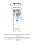
Figure 1 ERT 1557 Front View
Figure 2 ERT 1557 End View
-2-
ERT1557
Operating Instructions
Limited Warranty & Limitation of Liability
SEAWARD Electronic Limited guarantees this product
to be free from defects in material and workmanship
under normal use and service for a period of 1 year.
The period of warranty will be effective at the day of
delivery.
(c) Copyright 2008
All rights reserved. Nothing from this edition may be
multiplied, or made public in any form or manner,
either electronically, mechanically, by photocopying,
recording, or in any manner, without prior written
consent from SEAWARD Electronic Limited. This also
applies to accompanying drawings and diagrams.
Due to a policy of continuous development SEAWARD
Electronic Limited reserves the right to alter the
equipment specification and description outlined in
this publication without prior notice and no part of this
publication shall be deemed to be part of any contract
for the equipment unless specifically referred to as an
inclusion within such contract.
-3-
ERT1557
Operating Instructions
Disposal of Old Product
This product has been designed and manufactured
with high quality materials and components that can
be recycled and reused.
When the crossed out wheelie bin symbol is attached
to a product it means the product is covered by the
European Directive 2002/96/EC.
Please familiarise yourself with the appropriate local
separate collection system for electrical and electronic
products.
Please dispose of this product according to local
regulations. Do not dispose of this product along with
normal waste material. The correct disposal of this
product will help prevent potential negative
consequences for the environment and human health.
-4-
ERT1557
Operating Instructions
Table of Contents
Table of Contents ...................................................5
CERTIFICATE OF CONFORMITY............................6
Introduction ............................................................7
1 User Notes ..........................................................8
2 Safety Notes........................................................9
3 Accessories.......................................................10
3.1 Standard Accessories.................................10
3.2 Optional Accessories..................................10
4 Unit Description.................................................11
4.1 Identifying parts of the unit .........................11
4.2 LCD display messages ...............................11
4.3 Keypad operation .......................................12
5 Using the ERT 1557...........................................13
5.1 Power On ...................................................13
5.2 Battery Health Check..................................13
5.3 RA 3 Pole ...................................................13
5.4 RA Using current clamp...............................14
5.5 RA 4 Pole ...................................................15
6 Memory Functions .............................................16
6.1 Memory locations .......................................16
6.2 Storing results ............................................16
6.3 Recalling Results ........................................17
6.4 Erasing individual results ............................18
6.5 Clearing all the memory ..............................18
7 Download Function ............................................20
7.1 COM Port Identification ..............................20
7.2 Hyper Terminal Setup Procedure................21
7.3 Download Data...........................................22
7.4 View Download Data ..................................23
8 Electrical Specifications .....................................25
8.1 Earth Resistance Two/Three Pole Method ..25
8.2 Earth Resistance Current Clamp Method....25
8.3 Specific Earth Resistance ...........................26
9 Environmental Conditions ..................................27
10 Maintenance ....................................................28
10.1 Securing the ERT 1557 .............................28
10.2 Cleaning ...................................................28
10.3 Battery Replacement ................................29
10.4 Service and Calibration.............................29
10.5 Spare Parts...............................................30
-5-
ERT1557
Operating Instructions
CERTIFICATE OF CONFORMITY
As the manufacturer of the apparatus listed, Seaward
declare under our sole responsibility that the product:
ERT 1557
To which this declaration relates are in conformity with
the relevant clauses of the following standard:
BS EN 61010-1:2001
Safety requirements for electrical equipment for
measurement, control, and laboratory use – Part 1:
General requirements.
BS EN 61557-1, -5 :1997
Electrical safety in low voltage distribution systems
up to 1000V a.c. and 1500V d.c. – Equipment for
testing, measuring and monitoring of protective
measures
BS EN 61326:1998
Electrical equipment for measurement, control and
laboratory user-EMC Requirements
Performance: The instrument operates within
specification when used under the conditions in the
above standards EMC and Safety Standards.
The product identified above conforms to the
requirements of Council Directive 89/336/EEC and
73/23 EEC.
Seaward Electronic Ltd is registered under BS EN
ISO9001:2000 Certificate No: Q05356.
-6-
ERT1557
Operating Instructions
Introduction
The ERT 1557 is a fully featured earth resistance and
soil resistivity tester, housed in a rugged PrimeTest
series enclosure, and supplied complete with all
necessary test leads and test spikes. The instrument
will perform tests in accordance with BS7671 and
IEC61557.
The instrument is capable of 2, 3 and 4 pole resistance
measurement and earth resistance using a current
clamp. Up to 500 measurements can be stored in
memory, indexed via a simple reference numbering
system. Results can be downloaded to PC.
-7-
ERT1557
Operating Instructions
1 User Notes
This instrument and its operating instructions are
intended for use by adequately trained personnel.
The following symbols are used in these operating
instructions and on the ERT 1557.
Warning of electrical danger!
Indicates instructions must be followed to
avoid danger to persons.
Important, follow the documentation! This
symbol
indicates
that
the
operating
instructions must be adhered to in order to
avoid danger.
-8-
ERT1557
Operating Instructions
2 Safety Notes
This ERT 1557 is fully compliant with the requirements
of:
BS EN 61010-1: 2001.
BS EN 61557 part 1 and 5.
In order to ensure safe operation of this instrument, all
notes and warnings in these instructions must be
observed at all times.
The ERT 1557 has been designed to make
measurements in a dry environment.
The ERT 1557 may be used to test circuits with
a maximum overvoltage Category II, 300V
AC/DC with reference to earth.
The ERT 1557 and all associated cables and
leads must be checked for signs of damage
before equipment is operated.
Where safe operation of the ERT 1557 is no longer
possible it should be immediately shut down and
secured to prevent accidental operation.
It must be assumed that safe operation is no longer
possible:
- if the instrument or leads show visible signs of
damage or
- the instrument does not function or
- after long periods of storage under adverse
environmental conditions.
If the ERT 1557 is used in a manner not
specified by this document then the protection
provided by the equipment may be impaired.
-9-
ERT1557
Operating Instructions
3 Accessories
3.1 Standard Accessories
The ERT 1557 is supplied with the following items:
1 off ERT 1557 unit
1 off 5 m black test lead
1 off 20 m red test lead
1 off 5 m green test lead
1 off 20 m blue test lead
1 off USB to MiniDIN Lead Assembly
1 off Operating Instruction Manual
4 off test spikes
3.2 Optional Accessories
Current Clamp
Carry case
Seaward Part No 278A923
Seaward Part No 270A951
Do not open unit no serviceable parts
- 10 -
ERT1557
Operating Instructions
4 Unit Description
The ERT 1557 is a hand held, earth resistance tester.
Tests are selected using the rotary switch.
4.1 Identifying parts of the unit
The numbering below refers to fig. 1 and fig. 2.
1.
2.
3.
4.
5.
6.
7.
8.
LCD Display
Function keys F1, F2, F3 and F4
TEST key
Rotary Switch
Test lead inputs Es, E, S and H
Current clamp input
Current clamp input
Data port
4.2 LCD display messages
Display
>50kW
>2kW
>1999kWm
▲
RP
RC
No
001
0.0.1
Alternate
E-ES/ES-S
Stor
RCL
Prt
Meaning
Result is above the measuring range
for 2 and 3 point earth resistance
Result is above the measuring range
for current clamp earth resistance
Result is above the measuring range
for earth resistivity
More than 20Veff noise present. The
ERT 1557 is unable to make a
measurement.
The resistance between the Potential
test spike and earth is too high.
The resistance between the Current
test spike and earth is too high.
Request cannot be executed e.g.
result cannot be stored in a particular
memory location or particular result
cannot be recalled.
Memory location identifier
Measurement location identifier
The ES and E connections are
reversed. Correct the problem to
proceed
Storing result
Recalling result
Downloading data mode
- 11 -
ERT1557
Clr
Operating Instructions
Deleting a result from memory
4.3 Keypad operation
Key
F1
F4 + F1
F2
F4 + F2
F3
F4 + F3
TEST
Function
Increase numerical value
Recall data from memory
Decrease numerical value
Save result to memory
Select distance between test spikes.
Clear memory
Start measurement
- 12 -
ERT1557
Operating Instructions
5 Using the ERT 1557
5.1 Power On
To turn the ERT 1557 on simply rotate the rotary
switch to the required test type.
5.2 Battery Health Check
The ERT 1557 will automatically perform battery health
checks prior to a test performing.
Note: When the battery symbol is flashing all tests
will be inhibited and the batteries should be
replaced as described in section 8.4.
Do not connect any voltage or power source to
the current clamp inputs. Damage to the ERT
1557 will occur.
5.3 RA 3 Pole
Always ensure that the circuit under test is
<30Vrms.
5.3.1 Rotate the rotary switch until the RA 3pole test is
selected.
ERT 1557
E
ES
Earth
Electrode
S
Potential
Electrode
Figure 3
- 13 -
H
Current
Electrode
ERT1557
Operating Instructions
5.3.2 Connect the Es and E test leads to the test point.
5.3.3 Connect the H and S test leads to the 2 test
spikes as shown in figure 3.
5.3.4 Press and release the TEST key. The measured
resistance will appear on the LCD after a few
seconds. To save the result, refer to section 6.2.
5.4 RA Using current clamp
Always ensure that the circuit under test is
<30Vrms.
5.4.1 Rotate the rotary switch until the RA
selected.
test is
5.4.2 Connect the Es and E test leads to the test point.
5.4.3 Connect the H and S test leads to the 2 test
spikes as shown in figure 4.
CLAMP
ERT 1557
End Panel
Clamp input
Top panel
E
ES
S
Potential
Electrode
R E1
R E2
R E3
R En
Figure 4
- 14 -
H
Current
Electrode
ERT1557
Operating Instructions
5.4.4 Press and release the TEST key. The measured
resistance will appear on the LCD after a few
seconds. To save the result, refer to section 6.2.
5.5 RA 4 Pole
5.5.1 Rotate the rotary switch until the RA 4pole test is
selected.
5.5.2 Connect the Es, E, H and S test leads to the test
spikes.
5.5.3 Insert the test spikes into the ground in the order
E, Es, S and H. Ensure the spikes are equispaced.
5.5.4 Input the appropriate distance between the test
spikes into the ERT1557 by pressing the F3
(Distance) function key. Press F1 (D) or F2 (Ñ)
function keys to either increment or decrement
the distance, in metres.
5.5.5 To perform the soil resistivity test press and
release the TEST function key.
5.5.6 The measured soil resistivity will appear on the
LCD after a few seconds. To save the result,
refer to section 6.2
ERT 1557
E
ES
S
Potential
Electrode
Figure 5
- 15 -
H
Current
Electrode
ERT1557
Operating Instructions
6 Memory Functions
6.1 Memory locations
All memory locations are allocated a unique index
number that is comprised of an identification code,
object identification number and measuring place.
Function code numbers are:1 = RA Two-point & Three-point test
2 = RA
Clamp System Earth Resistance test
3 = RA Soil Resistivity test
Object identification numbers can be selected
between 001 and 999.
Measuring place can be selected between 0.0.1 and
9.9.9.
6.2 Storing results
6.2.1. Begin test measurement, the value of the
measured resistance is displayed on LCD.
6.2.2. To store the result displayed on the LCD press
the F4 (shift) + F2 (save) function keys to enter
the storage mode. As an indication the small
object identification number is displayed on the
LCD.
6.2.3. Press F1 (D) or F2 (Ñ) function keys to select the
desired object identification number.
6.2.4. Press F4 (Shift) + F2 (Ñ) function keys once
again to select the measuring place number.
6.2.5. Press F1 (D) or F2 (Ñ) function keys to select the
desired measuring place.
- 16 -
ERT1557
Operating Instructions
Each test resistance result can only be stored
once at any selected object identification
number or measuring place. If an attempt is
made to store a result in a location already
utilised the LCD displays no.
6.2.6. Press F4 (Shift) + F2 (Ñ) function keys once
again to save the test result under both the
selected object identification number and
measuring place. The LCD displays Stor on the
viewing screen before storing the resistance
value.
6.3 Recalling Results
6.3.1. To Recall a stored result press F4 (Shift) + F1
(Recall) function keys to enter recall mode. As
an indication the small object identification
number and RCL are displayed in the bottom
right hand corner of the LCD.
6.3.2. Press F1 (D) or F2 (Ñ) function keys to select the
desired object identification number.
6.3.3. Press (F4) Shift + F1 (Recall) function keys once
again to select the measuring place field.
6.3.4. Press F4 (Shift) + F2 (Ñ) function keys once
again to select the measuring place number.
6.3.5. Press (F4) Shift + F1 (Recall) function keys once
again to recall the result at the selected memory
location and identified by both the selected
object code and measuring place number.
6.3.6. The LCD display firstly indicates the function
test code for one second, followed by the
optional distance measurement (a
requirement of the RA
Clamp test)
followed by the stored earth resistance value.
- 17 -
ERT1557
Operating Instructions
6.3.7. If there are no stored results in the selected
memory location then a message no is
displayed on the LCD.
6.3.8. Repeat step 6.3.1 to recall results from other
memory locations.
6.4 Erasing individual results
6.4.1. Press F4 (Shift) + F1 (Recall) function keys to
enter recall mode. As an indication the small
object identification number and RCL are
displayed in the bottom right hand corner of the
LCD.
6.4.2. Press F1 (D) or F2 (Ñ) function keys to select the
desired object identification number.
6.4.3. Press (F4) Shift + F1 (Recall) function keys once
again to select the measuring place field.
6.4.4. Press F4 (Shift) + F2 (Ñ) function keys once
again to select the measuring place number.
6.4.5. Press F4 (Shift) +F3 (Distance) function keys to
clear the displayed earth resistance. The LCD
display will indicate Clr.
6.4.6. When an attempt is made to clear a memory
location where no result is stored then the
message no is displayed on the LCD.
6.5 Clearing all the memory
6.5.1. Select the rotary switch to Data Clear position.
6.5.2. Press F4 (Shift) +F3 (Distance) function keys to
clear all memory locations. As an indication
message Clr starts blinking on the LCD display.
6.5.3. Press F4 (Shift) +F3 (Distance) function keys
once again to erase the whole memory. The LCD
- 18 -
ERT1557
Operating Instructions
display goes blank indicating that erasing of
memory is in progress. Once the memory is
erased a message Clr is indicated on the
display.
- 19 -
ERT1557
Operating Instructions
7 Download Function
To download data the operator must connect the
ERT1557 to a computer using the supplied USB to
miniDin connector and the hyper terminal
communications program supplied with the computer.
Always ensure that the USB cable assembly is
not connected to a computer before performing
any of the test functions available with an ERT
1557.
7.1 COM Port Identification
7.1.1 Identification of the COM port, utilised by the
ERT1557, is dependent on the operating system
used by that computer.
7.1.2 The following is a guide for a computer with an
XP operating system and should be viewed for
reference only where computers with alternative
operating systems are employed.
7.1.3 Right click on the My Computer icon from the
computer desktop menu. Select the Manage
function from the displayed list.
7.1.4 Select Device Manager from the Computer
Management pop up box. From the list of
devices select Ports (COM & LPT).
- 20 -
ERT1557
Operating Instructions
7.1.5 Identify the COM port associated with CP210x
USB to UART Bridge Controller. This is COM4,
in the example shown.
7.2 Hyper Terminal Setup Procedure
7.2.1. Install the USB driver provided as part of the
supplied accessories on a PC (Depending on
the computer operating system).
7.2.2 Some computer operating systems are not
supplied with the hyper terminal program. In this
case the program can be downloaded free from
the internet.
7.2.2 Open the hyper terminal communications
program on the PC (Path:-start / All Programs /
Accessories / Communications / HyperTerminal).
7.2.3 Enter the name of the hyper terminal connection
e.g. ERT Download. Click on the OK prompt
softkey and select the appropriate COM port to
which the USB is connected. Click on the OK
prompt softkey.
7.2.4 Hyper Terminal configuration port settings are:Baud Rate
No of Data bits
Parity
Stop bit
Flow Control
4800 Bps
8
None
1
None
Click on the OK Prompt softkey.
7.2.5 The following screen is displayed on the PC
monitor.
- 21 -
ERT1557
Operating Instructions
7.3 Download Data
7.3.1 Select the Data Send function on the rotary
switch. As an indication Prt is displayed on the
LCD display.
7.3.2 Select Transfer pull-down menu in the hyper
terminal window. Select the Receive File option.
7.3.3 Using the Browse softkey select the destination
folder where the data file in the ERT1557 can be
stored. Use the receiving protocol drop-down
box to select the Xmodem protocol from the
available list.
7.3.4 Click on the Receive prompt softkey and enter a
filename that the ERT1557 data will be stored
within.
- 22 -
ERT1557
Operating Instructions
7.3.5 Press the TEST button on the ERT1557 then
click on the OK prompt softkey. The data file
from the ERT1557 is now downloaded to the
previously specified file Example Download.txt.
7.3.6 The Xmodem window is displayed during
downloading of data and closed on successful
completion of the download function.
7.4 View Download Data
7.4.1 The operator can now access the data download
file specified in 7.2.4.
7.4.2 The data is displayed in the format indicated
below
7.4.3 Where OBJ and PLACE represent the object
identification number and measuring place
respectively. These identify the memory location
where the result has been stored.
- 23 -
ERT1557
Operating Instructions
7.4.4 Earth Resis identifies the 2 and 3 point earth
resistance test method.
7.4.5 Clamp Resis identifies the earth resistance
clamp test method.
7.4.6. SRT Resis identifies the soil Resistivity test
method.
7.4.7 Where D is the repeatable distance between all
earth spikes in metres. E.g. D = 01 specifies a
distance of 1 metre.
- 24 -
ERT1557
Operating Instructions
8 Electrical Specifications
8.1 Earth Resistance Two/Three Pole Method
Display Range
Measurement
Ranges
Accuracy
Measuring
frequency
Measuring
current
Measuring
voltage
Distortion
0.00W to 50.0kW
0Ω - 19.99Ω
Resolution 0.01Ω
20Ω - 199.9Ω
Resolution 0.1Ω
200Ω - 199.9Ω
Resolution 1Ω
1.00KΩ - 9.99KΩ Resolution 10Ω
10.0KΩ - 50.0KΩ Resolution 100Ω
2% ± 2 counts from 0Ω - 999Ω
5% ± 2 counts from 1.00kΩ - 50.0kΩ
125 Hz ± 1HZ
<20mA effective
<30V effective sine wave
Max 5V p-p / 50Hz
8.2 Earth Resistance Current Clamp Method
Display Range
Measurement
Ranges
0.00W to 2.0kW
0.5Ω - 19.9Ω Resolution 0.1Ω
20Ω – 999Ω
Resolution 1Ω
1.00Ω - 2.00kΩ Resolution 10Ω
5% + 2 counts
125 Hz ± 1Hz
Accuracy
Measuring
frequency
Measuring
<20mA effective
current
Measuring
<30V effective sine wave
voltage
Distortion
Max 5V p-p / 50Hz
Note: the stated accuracy of the earth resistance
current clamp method does not include errors
introduced by the current clamp
- 25 -
ERT1557
Operating Instructions
8.3 Specific Earth Resistance
Display
Range
Measurement
Ranges
Accuracy
Measuring
frequency
Measuring
current
Measuring
voltage
Distortion
0.00Wm to 320kWm
0Wm –19.99Wm
Resolution 0.01Wm
20Wm – 199.9Wm
Resolution 0.1Wm
200Wm - 999Wm
Resolution 1Wm
1.00kWm – 9.99kWm Resolution 10Wm
10.00kWm –99.9kWm Resolution 100Wm
100kWm – 320kWm Resolution 1kWm
2% ± 2 counts 0Wm – 6.3kWm
5%
6.3kWm – 320kWm
125 Hz ± 1Hz
<20mA effective
<30V effective sine wave
Max 5V p-p / 50Hz
- 26 -
ERT1557
Operating Instructions
9 Environmental Conditions
9.1 The ERT 1557 has been designed to perform tests
and measurements in a dry environment.
9.2 Maximum barometric elevation for making
measurements is 2000M.
9.3 Overvoltage category IEC 60664/IEC 61010, 300V
Category II.
9.4 Pollution degree 2 according to IEC 61010-1.
9.5 Protective system IP40 according to IEC 60529.
9.6 Electromagnetic compatibility (EMC). Interference
immunity and emitted interference conforming to
IEC 61326-1.
9.7 Operating temperature range of 0°C to 40°C,
without moisture condensation.
9.8 The ERT 1557 can be stored at any temperature in
the range -25°C to +65°C (relative humidity up to
90%). The batteries should be taken out of the
instrument for storage.
9.9 Operating Altitude 0 to 2000 metres
- 27 -
ERT1557
Operating Instructions
10 Maintenance
10.1 Securing the ERT 1557
Under certain conditions safe operation of the ERT
1557 can no longer be assumed:
10.1.1 Visible damage of the instrument case.
10.1.2 Incorrect measurement results.
10.1.3 Recognisable abuse to the instrument due to
prolonged storage under improper conditions.
10.1.4 Recognisable abuse to the instrument due to
extraordinary transportation stress.
10.1.5 Check the battery compartment for signs of
battery electrolyte leakage.
10.1.6 In these cases, the ERT 1557 should be
immediately switched off, disconnected from
any test or measurement function and secured
to prevent any further use.
10.2 Cleaning
10.2.1 Clean the external case of the ERT 1557 with a
clean dry cloth.
10.2.1 Avoid using solvents and abrasive scouring
agents to clean the external case of the ERT
1557.
10.2.3 Check the battery contacts and compartment
are free of electrolytic contamination.
10.2.4 Any contamination of the battery contacts or
compartment should be cleaned with a dry
cloth.
- 28 -
ERT1557
Operating Instructions
10.3 Battery Replacement
Before opening the ERT1557 ensure that it is
disconnected from all voltages! Electric shock
danger!
10.3.1 Power the unit off by selecting the Off position
on the rotary switch.
10.3.2 Disconnect all the test leads from the unit
10.3.3 Position the ERT 1557 face down and release
the captive screw in the battery compartment
cover.
10.3.4 Remove the battery compartment cover.
10.3.5 Remove the discharged batteries from the
compartment.
10.3.6 Fit a new set of alkaline batteries.
10.3.7 Relocate the battery cover over the battery
compartment and fasten in position with the
battery cover captive screw.
10.4 Service and Calibration.
To maintain the specified accuracy of the
measurement results, the instrument must be
recalibrated at regular intervals by either the
manufacturer or an authorised Seaward Service Agent.
We recommend a recalibration period of one year.
- 29 -
ERT1557
Operating Instructions
10.5 Spare Parts.
Test Cable Kit
USB to MiniDIN Lead
Assembly
Carrying Case
Seaward Part No.
44B167
362W505
270A951
For Service and Calibration contact:
Service Department
Seaward Electronic
Bracken Hill
South West Industrial Estate
Peterlee
Co Durham SR8 2SW
England
Tel: 0191 5878739 / 0191 5878737
Email: [email protected]
- 30 -
ERT1557
Operating Instructions
362A550 Rev 1
- 31 -