1
Operating instructions
Betriebsanleitung
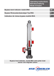
Bypass level indicator model BNA
GB
Bypass-Niveaustandsanzeiger Typ BNA
D
Bypass level indicator, model BNA with option level
sensor and magnetic switch
D
Operating instructions bypass level indicator
Model BNA
Page 3-16
Betriebsanleitung Bypass-Niveaustandsanzeiger
Typ BNA
Seite 17-30
2
WIKA operating instructions bypass level indicator model BNA
112195.01 11/2012 GB/D
GB
Contents
Contents
GB
1.
Safety instructions
4
3.
Installation and commissioning
7
2.
4.
5.
Description of functions and design
Maintenance
Error detection
6
15
16
WARNING!
Instructions on correct installation and proper operation.
Non-observance of these instructions can lead to
malfunction or damage.
112195.01 11/2012 GB/D
DANGER!
Instructions which must be complied with to avoid injury or
property damage.
Information
Facts and information concerning proper operation.
WIKA operating instructions bypass level indicator model BNA
3
1. Safety instructions
1. Safety instructions
Please read these instructions carefully before installing
and commissioning the model BNA bypass level indicator.
These instructions are directed to trained personnel implementing the assembly, installation and set-up of the system.
The bypass level indicator serves for continuously measuring the level of liquids in vessels. Use it for no purpose
other than this. No liability will be assumed by the manufacturer for damage resulting from use other than specified!
The bypass level indicator has been designed, manufactured and tested in accordance with the state of art and the
accepted safety regulations. Notwithstanding this, certain
risks might be involved.
GB
The following safety instructions should, therefore, be observed:
Do not modify, supplement or change the bypass level indicator unless
with manufacturer’s express approval. Unauthorised changes or
non-permitted use will result in immediate loss of warranty or liability
claims.
The installation, operation and maintenance must be performed by
expert and authorised personnel only. The required expertise must be
obtained by regular training.
Prior to starting operation please check all devices for their proper
connection, operability and power supply. This shall also apply to
assemblies coupled thereto.
4
WIKA operating instructions bypass level indicator model BNA
112195.01 11/2012 GB/D
It is imperative for operators, installers and servicers to comply with
all applicable safety regulations. This provision shall extend to all local
safety and accident preventing regulations not expressly referred to
herein.
1. Safety instructions
The general operating instructions of all devices as used must be
abided by.
GB
Measures must be taken preventing personal injuries and damage to
property from occurring in case of a defective condition of the bypass
level indicators.
The bypass level indicator must not be operated in the direct vicinity of
ferromagnetic environments (min. distance 50 mm) or strong electromagnetic fields (min. distance 1 m).
The bypass level indicator must not be exposed to heavy mechanical
strain.
The maximum power and voltage values for the intrinsically safe operation as specified in the assembling and operating instructions should be
adhered to.
112195.01 11/2012 GB/D
The safe operation of the system with a view to
pressure and temperature of the materials as employed shall be the operator’s responsibility.
The medium to be monitored must not be heavily soiled
or contain coarse particles. It must not tend to stick or
crystallise, as otherwise the perfect function cannot be
guaranteed.
The bypass level indicators may only be used in accordance
with the maximum values for pressure and temperature as
stated on the product label. Exceeding these parameters
can lead to malfunctions or to the destruction of the bypass
level indicator and may cause personal injury or damage to
property. All materials of the bypass tube and the float must
be resistant to the medium to be monitored.
WIKA operating instructions bypass level indicator model BNA
5
1. Safety instructions / 2. Functional description ...
The maximum values specified on the product label
must be observed to guarantee trouble-free operation. At
temperatures over 60 °C, a warning sign has to be attached
to flanges, tubes, case etc., warning explicitly of the danger
of burning and suitable protective measures must also be
taken.
GB
The float has been designed for the medium density
specified on the product label. When the float is used in
liquids with another specific weight, deviations can occur
during measurement.
DANGER!
Work in containers involves the danger of intoxication and
suffocation. No work is allowed to be carried out unless by
taking suitable personal protective measures (e.g. respiratory protection apparatus, protective outfit etc.).
Danger of explosion
Inside the container, there is danger of an explosive atmosphere. Corresponding measures for preventing sparking
should be taken. No work is allowed in this area unless by
technically skilled staff in accordance with applicable safety
regulations.
WIKA bypass level indicators work according to the principle of
communicating vessels. The bypass vessel contains a float with a builtin permanent magnet. This rises and falls with the level of the medium.
Optical and electrical level indicators or limit switches are mounted
to the outside of the bypass tube and actuated by the magnetic field.
Evaluation of the filling level by guided radar is also possible. The fitting
6
WIKA operating instructions bypass level indicator model BNA
112195.01 11/2012 GB/D
2. Functional description and design
2. Functional description and ... / 3. Installation and ...
of these options is carried out according to specific customer wishes in
the factory.
The principle structure is shown in figure 1. Customer-specific versions
are executed to order.
Transport and storage
Transport and storage for bypass level indicators are only allowed in
designed packaging.
Removal of transport packaging and transportation safety devices
Remove the bypass level indicator carefully from the transport
packaging.
Please observe the instructions given on the shipment packaging and
remove all transportation safety devices before taking out the bypass
level indicator.
Never use force to remove the bypass level indicator from the
packaging!
Before fitting, loosen the float attached on the outside of the bypass
level indicator from the bypass vessel. Make sure that all parts of the
packaging have been removed and the float can move freely in the
bypass reference vessel.
3. Installation and commissioning
112195.01 11/2012 GB/D
Remove the protective caps on the process connections
before fitting. Check the connection dimensions (centre to
centre distance) and the alignment of the process connections on the vessel. There must not be any mechanical
damage on the sealing faces of the vessel or the bypass
level indicator.
The magnetic roller display and any installed magnetic switches must
be aligned. To do this, slowly move the enclosed float from bottom to
top on the magnetic roller display and then back down again. Magnetic
switches must be aligned on the basis of the same principle. In the case
of bypass level indicators with insulation and magnetic roller displays
WIKA operating instructions bypass level indicator model BNA
7
GB
3. Installation and commissioning
with Plexiglass attachments, the float must be moved up and down
inside the tube. For magnetic roller displays with flushing connections,
GB these connections must have an airtight seal. Please refer in this case
to the mounting and operating instructions for WIKA magnetic roller
displays with flushing connections as well.
The bypass level indicator is mounted in a vertical position on the vessel
to be monitored using the process connections (1) provided. Seals
(2), screws (3), washers (4) and nuts (5) suitable for the process
connection must be used. Choose a seal with a suitable corrosion
resistance. If necessary, shut-off valves must be mounted between the
vessel and the bypass.
Please heed the usual torque values of screws used in
pipefitting work. The bypass level indicator must be installed
without tension. Suitable seals must be used. Care must
be taken that the seal material is resistant to the medium
and its vapours as well as to the temperature and pressure
loads to be expected.
Installing the float
■■ Clean the float of anything stuck on it in the area of the float magnet
system
■■ Remove the base flange (7) and insert the float (6) into the tube
from the bottom (the marking "top" or a legible model code marks the
top side of the float)
■■ Place the seal (9) onto the base flange. Replace the base flange
and fix it in place using the screws (8)
■■ Close draining and bleeding fittings on the bypass level indicator
8
WIKA operating instructions bypass level indicator model BNA
112195.01 11/2012 GB/D
Commissioning
If the bypass level indicator is fitted with shut-off valves between
process connections and tank, proceed as follows.
3. Installation and commissioning
■■ Slowly open the shut-off
valve at the upper process
connection
Fig. 1: Bypass level indicator, model BNA
GB
■■ Slowly open the shut-off
valve at the lower process
connection. As liquid flows
into the bypass vessel,
the float floats to the top.
The magnetic system
turns the magnetic rollers
of the optical indicator
from „light“ to „dark“.
The current filling level
is shown after liquid
equalisation between the
vessel and the bypass
level indicator
■■ Always heed the
112195.01 11/2012 GB/D
mounting and
operating instructions
of attachment devices
before putting them into
operation
T = upper projection
M = centre to centre distance
U = lower projection
WIKA operating instructions bypass level indicator model BNA
9
3. Installation and commissioning
The bypass tube can also be delivered in a heated doublewalled version. In this case, the bypass tube is surrounded
by a second tube. Heated liquid or steam (heat carrier) can
flow through this double-sheathed space via two connections. The materials for higher temperatures must be designed according to AD information sheets in non-corroding
qualities.
The heating sheath of the bypass level indicators may only
be used according to the specified maximum values for
pressure and temperature.
Attachment of the evaluation devices to the bypass level indicator
When attaching the evaluation devices (e.g.: WIKA sensors MG …,
WIKA magnetic switches) to the BNA …, the respective maximum
values of the field instrument must be heeded. The applicable laws or
directives for the use or the planned purpose of application must also be
observed.
Attachment example (sensor MG… to the bypass tube)
This description is only intended as an orientation aid for the
local installation situation. Please refer to the mounting and
operating instructions of the attachment devices as well.
10
WIKA operating instructions bypass level indicator model BNA
112195.01 11/2012 GB/D
GB
Installation and commissioning of the bypass level indicator in a
heated double-walled version
3. Installation and commissioning
Fig. 2: Sensor to the bypass tube
1
Sensor MG ...
2
Tightening strap
3
Magnetic roller display
4
Cheese-head screw or
comparable
5
Mounting clamp
6
Mounting lug
GB
Use the tightening strap or mounting
clamp (pos. 5) to attach the sensor
MG … to the bypass tube.
112195.01 11/2012 GB/D
The distance between the position
sensor (magnetic system in the
float) and the sensor tube should
not exceed 8 mm depending on the
magnetic system.
The bypass tube must never be
scored or drilled into or welded
directly.
WIKA operating instructions bypass level indicator model BNA
11
3. Installation and commissioning
Attachment example (magnetic switch to magnetic roller display)
The magnetic switch is attached to the magnetic roller level
display (4) of the bypass level indicator (6) by means of
sliding blocks (fig. 3).
GB
■■ Loosen the mounting screws (1) on the magnetic switch by about
one turn using an Allen key size 3 mm
■■ Push the sliding block(s) (2) into the guide groove (3) of the magnetic
roller display (4) from the top or the bottom. (Please note the position
of the cable connection or the plug as shown in the illustration)
■■ Push the magnetic switch to the height of the required switching
point and fix in place by tightening the screws (the switch point is
marked on the product label).
12
WIKA operating instructions bypass level indicator model BNA
112195.01 11/2012 GB/D
The magnetic switch MA has been designed for attachment
on the right-hand side of the magnetic roller display (4). If
it is mounted on the left-hand side, the switching function
is reversed. The switch has to be mounted the other way
round (product label is upside down).
3. Installation and commissioning
Fig. 3:
Mounting the magnetic switch (model M, ME, MST, MT)
GB
Switch point
112195.01 11/2012 GB/D
Mounting the magnetic switch (model MA)
WIKA operating instructions bypass level indicator model BNA
13
3. Installation and commissioning
Attachment example (magnetic switch to support bar)
These magnetic switches are fixed to a separately attached
support bar (fig. 4).
GB
■■ Remove the support bar (1) by loosening the mounting screws (2) and
removing the retaining plates (3) from the bypass stand seat
■■ Push the magnetic switch (4) onto the support bar (1)
■■ Attach the support bar (1) to the bypass tube (5) again using the
retaining plates (3) and mounting screws (2)
■■ Push the magnetic switch to the height of the required switch point
and fix in place by tightening the screws (6) (the switch point is
marked on the product label)
Please make sure during mounting that the cable entry and/
or the plug are pointing downwards. To guarantee a safe
switching function, the magnetic switch housing must rest
against the bypass tube.
14
WIKA operating instructions bypass level indicator model BNA
112195.01 11/2012 GB/D
Fig. 4: Mounting the magnetic switch (model MS, MV, MVT, MEx)
4. Maintenance
4. Maintenance
When used properly, bypass level indicators work maintenance-free.
They must be subjected to visual inspection within the context of regular
servicing, however, and included in the tank pressure test. (The test
pressure must not exceed the value specified on the product label!)
If the liquid to be measured contains dirt particles that could be
deposited in the bypass level indicator, the operator should clean the
bypass chamber at regular intervals.
DANGER!
Work on containers involves the danger of intoxication and
suffocation. No work is allowed to be carried out unless
by taking suitable personal protective measures (e.g.
respiratory protection apparatus, protective outfit etc.). The
bypass vessel can be under pressure. There might be a hot,
poisonous, caustic or explosive medium inside the bypass
vessel. Potential injury hazard due to splashing liquid,
burns to hands, arms, feet and face are possible, as well as
chemical burns, poisoning or explosions. Vessel pressure
has to be released before opening.
112195.01 11/2012 GB/D
Perfect functioning of the bypass level indicator can only be
guaranteed when original accessories and spare parts are
used.
WIKA operating instructions bypass level indicator model BNA
15
GB
5. Trouble shooting
5. Trouble shooting
GB The following table contains the most frequent causes of faults and the
necessary countermeasures.
Fault
Cause
Measure
Bypass level
indicator cannot
be fitted at the
planned place on
the vessel
Thread size or flange size of
the bypass level indicator do
not correlate
Modification of the vessel
Thread on the fastening
sleeve on the vessel is faulty
Mounting thread on the bypass level indicator is faulty
Centre to centre distance of
the vessel does not correlate
with the bypass level indicator
Rework the thread or replace
the fastening sleeve
Return to the factory
Process connections are
not attached parallel to one
another
Modification of the vessel
Return to the factory
Modification of the vessel
Return to the factory
16
WIKA operating instructions bypass level indicator model BNA
112195.01 11/2012 GB/D
Please contact us if you have any difficulties. We will be happy to help
any way we can.
Inhalt
Inhalt
1.
Sicherheitshinweise
18
3.
Installation und Inbetriebnahme
21
2.
4.
5.
Funktionsbeschreibung und Aufbau
Wartung
Fehlersuche
20
29
30
WARNUNG!
Hinweise zur fachgerechten Montage und den
bestimmungsgemäßen Betrieb. Eine Nichtbeachtung kann
zu Fehlfunktionen oder Beschädigungen führen.
112195.01 11/2012 GB/D
GEFAHR!
Hinweise deren Nichtbeachtung zu Personen- oder
Sachschäden führen können.
Information
Angaben und Informationen zur sachgerechten Anwendung.
WIKA Betriebsanleitung Bypass-Niveaustandsanzeiger Typ BNA
17
D
1. Sicherheitshinweise
1. Sicherheitshinweise
Lesen Sie diese Anleitung, bevor Sie den Bypass-Niveaustandsanzeiger Typ BNA installieren und in Betrieb nehmen.
Diese Anleitung richtet sich an Fachkräfte, die den Einbau,
die Installation und das Einrichten ausführen.
Der Bypass-Niveaustandsanzeiger dient zur kontinuierlichen Füllstandmessung von Flüssigkeiten in Behältern.
Verwenden Sie ihn ausschließlich für diesen Zweck. Für
Schäden, die aus nicht bestimmungsgemäßer Verwendung
resultieren, wird vom Hersteller keine Haftung übernommen!
Der Bypass-Niveaustandsanzeiger wurde entsprechend
dem Stand der Technik und den anerkannten sicherheitstechnischen Regeln entwickelt, gefertigt und geprüft.
Dennoch können von ihm Gefahren ausgehen.
D
Beachten Sie deshalb folgende Sicherheitshinweise:
Nehmen Sie am Bypass-Niveaustandsanzeiger keine Veränderungen,
An- oder Umbauten ohne vorherige Genehmigung des Herstellers vor.
Unbefugter Eingriff und unzulässige Verwendung führen zum Verlust von
Garantie- und Haftungsansprüchen.
Die Installation, Bedienung und Instandhaltung darf nur von fachkundigem, autorisiertem Personal ausgeführt werden. Fachkenntnisse
müssen durch regelmäßige Schulung erworben werden.
Vor Inbetriebnahme sind alle Geräte auf richtigen Anschluss und Funktion zu prüfen. Die elektrische Versorgung, auch der nachgeschalteten
Geräte, ist zu kontrollieren.
18
WIKA Betriebsanleitung Bypass-Niveaustandsanzeiger Typ BNA
112195.01 11/2012 GB/D
Bediener, Einrichter und Instandhalter müssen alle geltenden Sicherheitsvorschriften beachten. Dies gilt auch für die örtlichen Sicherheitsund Unfallverhütungsvorschriften, die in dieser Betriebsanleitung nicht
genannt sind.
1. Sicherheitshinweise
Die allgemeinen Betriebsanweisungen der verwendeten Geräte sind zu
beachten.
Es müssen Maßnahmen getroffen werden, die bei einem Defekt der
Bypass-Niveaustandsanzeiger verhindern, das Gefahren für Personen
und Sachen entstehen können.
Bypass-Niveaustandsanzeiger nicht in unmittelbarer Nähe ferromagnetischer Umgebung (Abstand min. 50 mm) oder starker elektromagnetischer Felder betreiben (Abstand min. 1 m).
Die Bypass-Niveaustandsanzeiger dürfen keiner starken mechanischen
Belastungen ausgesetzt werden.
Die in der Montage und Betriebsanleitung angegebenen maximalen
Strom- und Spannungswerte für den eigensicheren Betrieb sind einzuhalten.
112195.01 11/2012 GB/D
Der sichere Betrieb der Anlage im Hinblick auf Druck
und Temperatur der verwendeten Stoffe, obliegt dem
Betreiber.
Das zu überwachende Medium darf keine starke
Verschmutzung oder Grobteile aufweisen. Es darf nicht
zum Verkleben oder Auskristallisieren neigen um eine
einwandfreie Funktion zu gewährleisten.
Die Bypass-Niveaustandsanzeiger dürfen nur entsprechend
den auf dem Typenschild angegebenen Maximalwerten
für Druck und Temperatur eingesetzt werden. Ein
Überschreiten dieser Parameter kann zu Fehlfunktionen
oder der Zerstörung des Bypass-Niveaustandanzeigers
und zu Personen- oder Sachschäden führen. Sämtliche
Werkstoffe des Bypassrohres und des Schwimmers
müssen gegen das zu überwachende Medium beständig
sein.
WIKA Betriebsanleitung Bypass-Niveaustandsanzeiger Typ BNA
19
D
1. Sicherheitshinweise / 2. Funktionsbeschreibung ...
Die auf dem Typschild angegebenen Maximalwerte
sind zur Gewährleistung eines störungsfreien Betriebes
zu beachten. Bei Temperaturen über 60 °C an
Flanschen, Rohren, Gehäuse etc. muss ein Warnhinweis
angebracht werden, welcher deutlich vor den Gefahren
von Verbrennungen warnt bzw. müssen geeignete
Schutzmaßnahmen getroffen werden.
D
Der Schwimmer ist für die auf dem Typschild angegebene
Mediumsdichte ausgelegt. Bei der Verwendung in
Flüssigkeiten mit anderem spezifischen Gewicht entstehen
Abweichungen bei der Messung.
GEFAHR!
Beim Arbeiten in Behältern, besteht Vergiftungs- oder
Erstickungsgefahr. Arbeiten dürfen nur unter Anwendung
geeigneter Personenschutzmaßnahmen (z. B. Atemschutzgerät, Schutzkleidung o. Ä.). durchgeführt werden.
Achtung Explosionsgefahr
Im Behälter besteht die Gefahr explosionsfähiger
Atmosphäre. Es sind entsprechende Maßnahmen, die eine
Funkenbildung verhindern, zu ergreifen. Arbeiten in diesem
Bereich dürfen nur durch Fachpersonal entsprechend den
jeweiligen geltenden Sicherheitsrichtlinien durchgeführt
werden.
WIKA Bypass-Niveaustandsanzeiger arbeiten nach dem Prinzip
des kommunizierenden Gefäßes. In dem Gefäß befindet sich ein
Schwimmer mit eingebautem Permanentmagneten. Dieser ändert
seine Höhenlage mit dem Pegel des Mediums. Durch das Magnetfeld
werden außen am Bypassrohr angebrachte optische und elektrische
Füllstandsanzeigen oder Grenzwertschalter betätigt. Auch eine
20
WIKA Betriebsanleitung Bypass-Niveaustandsanzeiger Typ BNA
112195.01 11/2012 GB/D
2. Funktionsbeschreibung und Aufbau
2. Funktionsbeschreibung und ... / 3. Installation und ...
Auswertung des Füllstandes mit geführtem Radar ist möglich. Der
Anbau bzw. Einbau dieser Optionen erfolgt kundenspezifisch ab Werk.
Der prinzipielle Aufbau ist in Abb. 1 ersichtlich. Kundenspezifische
Ausführungen werden gemäß Auftrag ausgeführt.
Transport und Lagerung
Für Transport und Lagerung der Bypass-Niveaustandsanzeiger ist die
dafür vorgesehene Verpackung zu verwenden.
Entfernen der Transportverpackung und der Transportsicherungen
Den Bypass-Niveaustandsanzeiger vorsichtig aus der Transportverpackung entfernen.
Bitte beachten Sie die auf der Versandverpackung angegebenen
Hinweise und entfernen Sie vor der Entnahme alle Transportsicherungen.
Den Bypass-Niveaustandsanzeiger niemals gewaltsam aus der Verpackung entfernen!
Vor dem Anbau den außen am Bypass-Niveaustandsanzeiger
angebrachten Schwimmer vom Bypassgefäß lösen. Stellen Sie sicher,
dass alle Verpackungsteile entfernt wurden und der Schwimmer im
Bypassbezugsgefäß frei beweglich ist.
3. Installation und Inbetriebnahme
112195.01 11/2012 GB/D
Vor der Montage sind die Schutzkappen an den Prozessanschlüssen zu entfernen. Überprüfen Sie die Anschlussmaße
(Mittenabstand) und die Flucht der Prozessanschlüsse
am Behälter. An den Dichtflächen des Behälter bzw. des
Bypass-Niveaustandanzeigers dürfen keine mechanischen
Beschädigungen vorhanden sein.
Die Magnetrollenanzeige und eventuell angebaute Magnetschalter sind
auszurichten. Hierzu ist der beigefügte Schwimmer auf der Magnetrollenanzeige langsam von unten nach oben und anschließend wieder
nach unten zu bewegen. Angebaute Magnetschalter sind nach dem
gleichen Prinzip auszurichten. Bei Bypass-Niveaustandsanzeiger mit
Isolierung bzw. bei Magnetrollenanzeigen mit Plexiglasvorsatz muss
WIKA Betriebsanleitung Bypass-Niveaustandsanzeiger Typ BNA
21
D
3. Installation und Inbetriebnahme
der Schwimmer im Inneren des Rohres auf und ab bewegt werden.
Bei Magnetrollenanzeigen mit Spülanschlüssen sind diese luftdicht
zu verschließen. Bitte beachten Sie hierzu auch die Montage- und
Betriebsanleitung der Magnetrollenanzeige mit Spülanschlüssen.
D Der Bypass-Niveaustandsanzeiger wird mittels den vorgesehenen
Prozessanschlüssen (1), in einer vertikalen Position, an den zu
überwachenden Behälter montiert. Zur Montage sind zum Prozessanschluss passende Dichtungen (2), Schrauben (3), Unterlegscheiben (4) und Muttern (5) zu verwenden. Bei der Auswahl der Dichtung
ist auf entsprechende Korrosionsbeständigkeit zu achten. Bei Bedarf
sind Absperrarmaturen zwischen Behälter und Bypass zu montieren.
Bitte beachten Sie die im Rohrleitungsbau üblichen
Drehmomentwerte der Schrauben. Der Bypass-Niveaustandsanzeiger ist spannungsfrei einzubauen. Es sind
geeignete Dichtungen zu verwenden. Es ist sicherzustellen, dass das Dichtungsmaterial gegen das Medium und
dessen Dämpfe, sowie den zu erwartenden Temperaturund Druckbelastungen beständig ist.
Einbau des Schwimmers
■■ Den Schwimmer von eventuell anhaftenden Teilen im Bereich des
Schwimmermagnetsystems reinigen
■■ Bodenflansch (7) abnehmen und Schwimmer (6) von unten in
Inbetriebnahme
Sofern der Bypass-Niveaustandsanzeiger mit Absperrventilen zwischen
Prozessanschlüssen und Behälter ausgerüstet ist wie folgt vorgehen.
■■ Entleer- und Entlüftungseinrichtungen am Bypass-Niveaustandsan-
zeiger schließen
22
WIKA Betriebsanleitung Bypass-Niveaustandsanzeiger Typ BNA
112195.01 11/2012 GB/D
das Rohr einführen (Beschriftung „top“ bzw. ein lesbarer Typcode
kennzeichnen die Oberseite des Schwimmers)
■■ Dichtung (9) auf den Bodenflansch auflegen. Bodenflansch wieder
aufsetzen und mittels Schrauben (8) befestigen
3. Installation und Inbetriebnahme
■■ Absperrventil am
oberen Prozessanschluss
langsam öffnen
Abb. 1: Bypass-Niveaustandsanzeiger
Typ BNA
■■ Absperrventil am
D
unteren Prozessanschluss
langsam öffnen. Mit der
einströmenden Flüssigkeit
ins Bypassgefäß
schwimmt der Schwimmer
auf. Das Magnetsystem
dreht die Magnetrollen
der optischen Anzeige
von der „hellen zur
„dunklen“ Seite. Nach
dem Flüssigkeitsausgleich
zwischen Behälter
und BypassNiveaustandsanzeiger
wird der aktuelle Füllstand
angezeigt
■■ Zur Inbetriebnahme
112195.01 11/2012 GB/D
von Anbaugeräten
unbedingt deren
Montage- und
Betriebsanleitung
beachten
T = oberer Überstand
M = Mittenabstand
U = unterer Überstand
WIKA Betriebsanleitung Bypass-Niveaustandsanzeiger Typ BNA
23
3. Installation und Inbetriebnahme
Installation und Inbetriebnahme des Bypass-Niveaustandsanzeiger in einer beheizten doppelwandigen Ausführung
Das Bypassrohr ist auch in einer beheizten doppelwandigen Ausführung zu beziehen. Hierbei wird das Bypassrohr mit einem zweiten Rohr umgeben. Der so gebildete
Doppelmantelraum kann über zwei Anschlüsse mit
erwärmter Flüssigkeit oder erhitztem Dampf (Wärmeträger)
durchströmt werden. Die Auslegung der Werkstoffe für die
höheren Temperaturen erfolgt nach AD-Merkblättem in
nichtrostenden Qualitäten.
D
Der Heizmantel der Bypass-Niveaustandsanzeiger darf nur
entsprechend den angegebenen Maximalwerten für Druck
und Temperatur eingesetzt werden.
Anbau der Auswertegeräte an den Bypass-Niveaustandsanzeiger
Beim Anbau der Auswertegeräte (z. B.: WIKA Messwertgeber MG ...,
WIKA Magnetschalter) an den BNA ... sind die jeweiligen Höchstwerte des Feldgerätes zu beachten. Die für die Verwendung bzw. den
geplanten Einsatzzweck zutreffenden Gesetze bzw. Richtlinien sind
einzuhalten.
Anbaubeispiel (Messwertgeber MG ... an Bypassrohr)
24
WIKA Betriebsanleitung Bypass-Niveaustandsanzeiger Typ BNA
112195.01 11/2012 GB/D
Die hier aufgeführte Beschreibung ist nur als Orientierungshilfe für die ortsgegebene Anbaumöglichkeit zu sehen.
Bitte beachten Sie auch die Montage und Betriebsanleitungen der Anbaugeräte.
3. Installation und Inbetriebnahme
Abb. 2: Messwertgeber an Bypassrohr
1
Messwertgeber MG ...
2
Spannband
3
Magnetrollenanzeige
4
Zylinderkopfschraube oder
vergleichbares
5
Befestigungsschelle
6
Befestigungslasche
D
Messwertgeber MG ... mit Spannband
oder Befestigungsschelle (Pos. 5) an
das Bypassrohr anbringen.
112195.01 11/2012 GB/D
Der Abstand zwischen Positionsgeber
(Magnetsystem im Schwimmer) und
Messwertgeberrohr sollte je nach
Magnetsystem 8 mm nicht überschreiten.
Das Bypassrohr darf auf keinem Fall
an- oder durchgebohrt bzw. direkt
verschweißt werden.
WIKA Betriebsanleitung Bypass-Niveaustandsanzeiger Typ BNA
25
3. Installation und Inbetriebnahme
Anbaubeispiel (Magnetschalter an Magnetrollenanzeige)
■■ Befestigungsschrauben (1) am Magnetschalter mittels Innensechs-
kantschlüssel SW 3 mm um ca. 1 Umdrehung lösen
■■ Nutenstein(e) (2) in die Führungsnut (3) der Magnetrollenanzeige (4)
von oben oder unten einschieben (Bitte beachten Sie die Lage der
Kabelverschraubung bzw. des Steckers gemäß Abb.)
■■ Magnetschalter auf die Höhe des gewünschten Schaltpunktes
verschieben und durch anziehen der Schrauben befestigen (Der
Schaltpunkt ist auf dem Typschild gekennzeichnet).
Der Magnetschalter MA ist für den Anbau an der rechten
Seite der Magnetrollenanzeige (4) ausgelegt. Bei Montage
auf der linken Seite kehrt sich die Schaltfunktion um. Der
Schalter muss umgekehrt montiert werden (Typenschild
steht auf dem Kopf).
26
WIKA Betriebsanleitung Bypass-Niveaustandsanzeiger Typ BNA
112195.01 11/2012 GB/D
D
Die Befestigung der Magnetschalter an der MagnetrollenNiveauanzeige (4) des Bypass-Niveaustandanzeigers (6)
erfolgt mit Nutensteinen (Abb. 3).
3. Installation und Inbetriebnahme
Abb. 3:
Magnetschaltermontage (Typ M, ME, MST, MT)
D
Schaltpunkt
112195.01 11/2012 GB/D
Magnetschaltermontage (Typ MA)
WIKA Betriebsanleitung Bypass-Niveaustandsanzeiger Typ BNA
27
3. Installation und Inbetriebnahme
Anbaubeispiel (Magnetschalter an Haltestange)
Die Befestigung dieser Magnetschalter erfolgt auf einer
separat angebrachten Haltestange (Abb. 4).
D ■■ Haltestange (1) durch Lösen der Befestigungsschrauben (2) und entfernen der Haltelaschen (3) vom Bypass-Standaufnehmer entfernen
■■ Magnetschalter (4) auf die Haltestange (1) aufschieben
■■ Haltestange (1) wieder am Bypassrohr (5) mittels Haltelaschen (3)
und Befestigungsschrauben (2) anbringen
■■ Magnetschalter auf die Höhe des gewünschten Schaltpunktes
verschieben und durch anziehen der Schrauben (6) befestigen (Der
Schaltpunkt ist auf dem Typschild gekennzeichnet)
Bitte beachten Sie bei der Montage, dass die Kabeleinführung bzw. der Stecker nach unten zeigt. Um eine sichere
Schaltfunktion zu gewährleisten, muss das Magnetschaltergehäuse am Bypassrohr anliegen.
28
WIKA Betriebsanleitung Bypass-Niveaustandsanzeiger Typ BNA
112195.01 11/2012 GB/D
Abb. 4: Magnetschaltermontage (Typ MS, MV, MVT, MEx)
4. Wartung
4. Wartung
Die Bypass-Niveaustandsanzeiger arbeiten bei bestimmungsgemäßem
Gebrauch wartungsfrei.
Sie sind jedoch im Rahmen der regelmäßigen Revision einer
Sichtkontrolle zu unterziehen und in die Druckprüfung des Behälters
mit einzubeziehen. (Der Prüfdruck darf den angegebenen Wert auf dem
Typschild nicht übersteigen!)
Enthält die zu messende Flüssigkeit Schmutzpartikel, die sich im
Bypass-Niveaustandsanzeiger absetzen können, sollte der Betreiber in
regelmäßigen Abständen die Reinigung des Standrohres vornehmen.
GEFAHR!
Beim Arbeiten an Behältern, besteht Vergiftungs- oder
Erstickungsgefahr. Arbeiten dürfen nur unter Anwendung
geeigneter Personenschutzmaßnahmen (z. B.
Atemschutzgerät, Schutzkleidung o. Ä.). durchgeführt
werden. Das Bypassgefäß kann unter Druck stehen.
Möglicherweise befindet sich heißes, giftiges, ätzendes
oder explosives Medium im Innern des Bypassgefäßes.
Es besteht Verletzungsgefahr durch herausspritzende
Flüssigkeit, Verbrennung an Händen, Armen, Füßen und
Gesicht sowie Verätzungen, Vergiftungen oder Explosionen.
Das Gefäß ist vor dem Öffnen zu entspannen.
112195.01 11/2012 GB/D
Die Funktion der Bypass-Niveaustandsanzeiger kann nur
bei Verwendung von Originalzubehör und Ersatzteilen
gewährleistet werden.
WIKA Betriebsanleitung Bypass-Niveaustandsanzeiger Typ BNA
29
D
5. Fehlersuche
5. Fehlersuche
BypassNiveaustandanzeiger lässt
sich nicht an der
vorgesehenen
Stelle am
Behälter anbauen
Gewindegröße oder Flanschgröße des Bypass-Niveaustandanzeiger stimmen nicht
überein
Gewinde der Befestigungsmuffe am Behälter defekt
Umbau des Behälters
Rücksendung ans Werk
Nacharbeiten des Gewindes
oder Austauschen der Befestigungsmuffe
Rücksendung ans Werk
Einschraubgewinde am
Bypass-Niveaustandanzeiger
defekt
Mittenabstand des Behälters Umbau des Behälters
stimmt nicht mit dem des
Bypass-Niveaustandanzeiger Rücksendung ans Werk
überein
Prozessanschlüsse sind
Umbau des Behälters
nicht parallel zueinander
angebracht
Rufen Sie uns bei allen Schwierigkeiten an. Wir sind bemüht Ihnen
jederzeit mit Rat und Tat zur Seite zu stehen.
30
WIKA Betriebsanleitung Bypass-Niveaustandsanzeiger Typ BNA
112195.01 11/2012 GB/D
D
In der folgenden Tabelle sind die häufigsten Fehlerursachen und die
erforderlichen Gegenmaßnahmen aufgeführt.
Fehler
Ursache
Maßnahme
WIKA global
Europe
Austria
WIKA Messgerätevertrieb
Ursula Wiegand GmbH & Co. KG
1230 Vienna
Tel.
(+43) 1 86916-31
Fax: (+43) 1 86916-34
E-Mail: [email protected]
www.wika.at
Benelux
WIKA Benelux
6101 WX Echt
Tel.
(+31) 475 535-500
Fax: (+31) 475 535-446
E-Mail: [email protected]
www.wika.nl
Bulgaria
WIKA Bulgaria EOOD
Bul. „Al. Stamboliiski“ 205
1309 Sofia
Tel.
(+359) 2 82138-10
Fax: (+359) 2 82138-13
E-Mail: [email protected]
112195.01 11/2012 GB/D
Croatia
WIKA Croatia d.o.o.
Hrastovicka 19
10250 Zagreb-Lucko
Tel.
(+385) 1 6531034
Fax: (+385) 1 6531357
E-Mail: [email protected]
www.wika.hr
Finland
WIKA Finland Oy
00210 Helsinki
Tel.
(+358) 9-682 49 20
Fax: (+358) 9-682 49 270
E-Mail: [email protected]
www.wika.fi
France
WIKA Instruments s.a.r.l.
95610 Eragny-sur-Oise
Tel.
(+33) 1 343084-84
Fax: (+33) 1 343084-94
E-Mail: [email protected]
www.wika.fr
Germany
WIKA Alexander Wiegand
SE & Co. KG
63911 Klingenberg
Tel.
(+49) 9372 132-0
Fax: (+49) 9372 132-406
E-Mail: [email protected]
www.wika.de
Italy
WIKA Italia Srl & C. sas
20020 Arese (Milano)
Tel.
(+39) 02 9386-11
Fax: (+39) 02 9386-174
E-Mail: [email protected]
www.wika.it
Poland
WIKA Polska S.A.
87-800 Wloclawek
Tel.
(+48) 542 3011-00
Fax: (+48) 542 3011-01
E-Mail: [email protected]
www.wikapolska.pl
Romania
WIKA Instruments Romania S.R.L.
Bucuresti, Sector 5
Calea Rahovei Nr. 266-268
Corp 61, Etaj 1
Tel.
(+40) 21 4048327
Fax: (+40) 21 4563137
E-Mail: [email protected]
WIKA Betriebsanleitung Bypass-Niveaustandsanzeiger Typ BNA
31
WIKA global
Russia
ZAO WIKA MERA
127015 Moscow
Tel.
(+7) 495-648 01 80
Fax:
(+7) 495-648 01 81
E-Mail: [email protected]
www.wika.ru
Switzerland
Manometer AG
6285 Hitzkirch
Tel.
(+41) 41 91972-72
Fax:
(+41) 41 91972-73
E-Mail: [email protected]
www.manometer.ch
Serbia
WIKA Merna Tehnika d.o.o.
Sime Solaje 15
11060 Belgrade
Tel. (+381) 11 2763722
Fax: (+381) 11 753674
E-Mail: [email protected]
www.wika.co.yu
Turkey
WIKA Instruments Istanbul
Basinc ve Sicaklik Ölcme Cihazlari
Bayraktar Bulvari No. 21
34775 Yukari Dudullu - Istanbul
Tel.
(+90) 216 41590-66
Fax:
(+90) 216 41590-97
E-Mail: [email protected]
www.wika.com.tr
Spain
Instrumentos WIKA, S.A.
C/Josep Carner, 11-17
08205 Sabadell (Barcelona)
Tel.
(+34) 902 902577
Fax: (+34) 933 938666
E-Mail: [email protected]
www.wika.es
Ukraine
WIKA Pribor GmbH
83016 Donetsk
Tel.
(+38) 062 34534-16
Fax:
(+38) 062 34534-17
E-Mail: [email protected]
www.wika.ua
Further WIKA subsidiaries worldwide can be found online at www.wika.com.
Weitere WIKA-Niederlassungen weltweit finden Sie online unter www.wika.de.
WIKA Alexander Wiegand SE & Co. KG
Alexander-Wiegand-Straße 30
63911 Klingenberg • Germany
Tel
(+49) 93 72/132-0
Fax
(+49) 93 72/132-406
E-Mail [email protected]
www.wika.de
32
WIKA Betriebsanleitung Bypass-Niveaustandsanzeiger Typ BNA
112195.01 11/2012 GB/D
Technical alteration rights reserved.
Technische Änderungen vorbehalten.