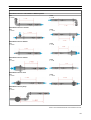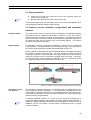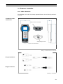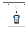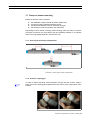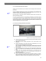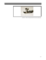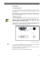
1
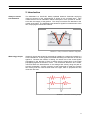
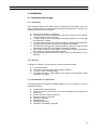
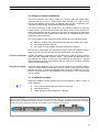
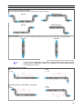
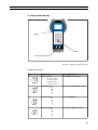
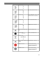
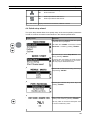
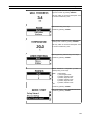
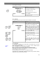
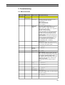
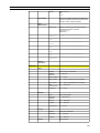
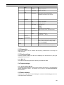
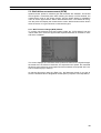
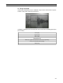
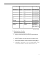
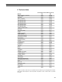
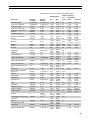
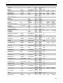
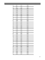
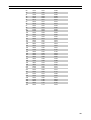
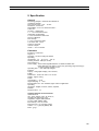
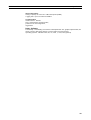
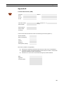
Operating Instructions Hand-held Ultrasonic Flowmeter Arkon Flow Systems, s.r.o. Nováčkova 11 614 00 Brno Czech Republic Tel. +420 543 214 822 Fax +420 543 215 249 Internet www.arkon.co.uk E-mail [email protected] Operating Instructions USCX200 Version V20EN140908 USCX200 Table of Content USCX200 Operating Instructions Contents Page 1 Safety instructions, legal requirements, warranty, return policy.................5 1.1 Symbols used in these operating instructions..............................................5 1.2 Safety instructions.......................................................................................5 1.3 Warranty...................................................................................................... 6 1.4 Return policy................................................................................................ 6 1.5 Legislative requirements..............................................................................6 2 Introduction...................................................................................................... 7 3 Installation........................................................................................................ 8 3.1 Unpacking and storage................................................................................8 3.1.1 Unpacking............................................................................................. 8 3.1.2 Storage and preservation.....................................................................8 3.1.3 Identification of components.................................................................8 3.2 Clamp-on sensor installation.......................................................................9 3.3 Installation location......................................................................................9 3.4 Pipe preparation.......................................................................................... 12 3.5 Clamp-on sensor mounting configurations and separation distance............12 3.6 Flowmeter installation..................................................................................13 3.6.13 Outline dimensions.............................................................................13 3.6.2 Electrical connections...........................................................................14 3.7 Clamp-on sensor mounting.........................................................................15 3.7.1 Sensor pipe mounting configurations....................................................15 3.7.2 Acoustic coupling gel............................................................................15 3.7.3 Correct positioning of the sensors........................................................16 3.7.4 Sensor mounting with fixtures and chains.............................................16 4 Operation.......................................................................................................... 18 4.1 Switching On/Off.......................................................................................... 18 4.2 Battery charging.......................................................................................... 18 4.3 Keypad and display.....................................................................................19 4.3.1 Keypad key functions............................................................................19 4.3.2 Display functions..................................................................................21 4.4 Quick setup wizard......................................................................................22 4.5 Measurements............................................................................................. 24 4.5.1 Main process value (PV) display...........................................................24 4.5.2 Diagnostic display.................................................................................25 4.5.3 Totalisers.............................................................................................. 25 4.5.4 Datalogger............................................................................................ 25 3 USCX200 Table of Content 5 Commissioning................................................................................................ 26 5.1 Menu structure............................................................................................ 26 5.2 Diagnostics.................................................................................................. 29 5.3 Display settings........................................................................................... 29 5.3.1 Main PV................................................................................................ 29 5.3.2 Line 1.................................................................................................... 29 5.4 Output settings............................................................................................ 29 5.4.1 Serial interface RS 232.........................................................................29 5.5 Data software.............................................................................................. 29 5.6 Wall thickness measurement (WTM)..........................................................29 5.6.1 Wall Thickness Gauge (WTG) Wizard..................................................30 5.7 Scope function............................................................................................. 31 6 Maintenance..................................................................................................... 32 7 Troubleshooting............................................................................................... 33 8 Technical data.................................................................................................. 35 9 Specification..................................................................................................... 41 10 Index................................................................................................................ 43 Appendix A - Certificate of Conformity..............................................................44 Appendix B - Customer Return Note (CRN)......................................................45 4 USCX200 1 Safety instructions, legal requirements, warranty, return policy 1 Safety instructions, legal requirements, warranty, return policy 1.1 Symbols used in these operating instructions ! ! Danger This symbol represents an immediate hazardous situation which could result in serious injury, death or damage to the equipment. Where this symbol is shown, do not use the equipment further unless you have fully understood the nature of the hazard and have taken the required precautions. Attention This symbol indicates important instructions which should be respected in order to avoid damaging or destroying the equipment. Follow the the precautions given in these instructions to avoid the hazard. Call our service team if necessary. Call service Where this symbol is shown call our service team for advice if necessary. • <ESC> Note This symbol indicates a note or detailed set-up tip. Information point. Operator keys are printed in bold typeface and placed in pointed brackets. 1.2 Safety instructions ● ● ● ● ● ● ● Do not install, operate or maintain this flowmeter without reading, understanding and following these operating instructions, otherwise injury or damage may result. Study these operating instructions carefully before the installation of the equipment and keep them for future reference. Observe all warnings, notes and instructions as marked on the packaging, on the equipment, and detailed in the operating instructions. Do not use the instrument under wet conditions with the battery cover removed or opened. Follow the unpacking, storage and preservation instructions to avoid damage to the equipment. Install the equipment and cabling securely and safely according to the relevant regulations. If the product does not operate normally, please refer to the service and troubleshooting instructions, or contact Arkon for help. 5 USCX200 1 Safety instructions, legal requirements, warranty, return policy 1.3 Warranty ● ● ● This product purchased from Arkon is warranted in accordance with the relevant product documentation and as specified in the sales contract provided it has been used for the purpose for which it has been designed and operated as outlined in these operating instructions. Misuse of the equipment will immediately revoke any warranty given or implied. Responsibility for suitability and intended use of this ultrasonic flowmeter rests solely with the user. Improper installation and operation of the flowmeter may lead to a loss of warranty. Please note that there are no operator-serviceable parts inside the equipment. Any unauthorised interference with the product will invalidate the warranty. 1.4 Return policy If the flowmeter has been diagnosed to be faulty, it can be returned to Arkon for repair using the Customer Returns Note (CRN) attached to the Appendix of this manual. Arkon regret that for Health & Safety reasons we cannot accept the return of the equipment unless accompanied by the completed CRN. 1.5 Legislative requirements CE marking The flowmeter is designed to meet the safety requirements in accordance with sound engineering practice. It has been tested and has left the factory in a condition in which it is safe to operate. The equipment is in conformity with the statutory requirements of the EC directive and complies with applicable regulations and standards for electrical safety EN 61010 and electro-magnetic compatibility EN 61326. A CE Declaration of Conformity has been issued in that respect, a copy of which can be found in the Appendix of these operating instructions. WEEE Directive The Waste Electrical and Electronic Equipment Directive (WEEE Directive) aims to minimise the impact of electrical and electronic goods on the environment by increasing re-use and recycling and by reducing the amount of WEEE going to landfill. It seeks to achieve this by making producers responsible for financing the collection, treatment, and recovery of waste electrical equipment, and by obliging distributors to allow consumers to return their waste equipment free of charge. Arkon offers its customers the possibility of returning unused and obsolete equipment for correct disposal and recycling. The Dustbin Symbol indicates that when the last user wishes to discard this product, it must be sent to appropriate facilities for recovery and recycling. By not discarding this product along with other household-type waste, the volume of waste sent to incinerators or landfills will be reduced and natural resources will be conserved. Please use the Customer Return Note (CRN) in the Appendix for return to Arkon. RoHS Directive All products manufactured by Arkon are compliant with the relevant aspects of the RoHS Directive. 6 USCX200 2 Introduction 2 Introduction Clamp-on transittime flowmeter The USCX200 is a hand-held, battery operated ultrasonic flowmeter employing clamp-on sensors for the measurement of liquids in full, enclosed pipes. Flow measurements can be undertaken without interruption of the process or interference with the integrity of the pipeline. The clamp-on sensors are attached to the outside of the pipes. The USCX200 uses ultrasonic signals for measurement of the flow, employing the transit-time method. Illustration 1: Clamp-on ultrasonic flowmeter configuration Measuring principle Ultrasonic signals are emitted by a transducer installed on a pipe and received by a second transducer. These signals are emitted alternately in the direction of flow and against it. Because the medium is flowing, the transit time of the sound signals propagating in the direction of flow is shorter than the transit time of the signal propagating against the direction of flow. The transit-time difference ΔT is measured and allows the determination of the average flow velocity along the path of acoustic propagation. A profile correction is then performed to obtain the average flow velocity over the cross-sectional area of the pipe, which is proportional to the volumetric flow rate. Illustration 2: Transit-time measuring principle 7 USCX200 3 Installation 3 Installation 3.1 Unpacking and storage 3.1.1 Unpacking Care should be taken when opening the box containing the flowmeter, any markings or warnings shown on the packaging should be observed prior to opening. The following steps should then be taken: ● ● ● ● ● ● ● Unpack the flowmeter in a dry area. The flowmeter should be handled with care and not left in an area where it could be subject to physical shocks. If using a knife to remove packaging care should be taken not to damage the flowmeter or cables. The flowmeter package and contents should be checked against the delivery note supplied and any missing items reported immediately. The flowmeter package and contents should be checked for signs of damage during transport and any problems reported immediately. The vendor accepts no responsibility for damage or injury caused during the unpacking of the instrumentation supplied. Excess packing materials should be either recycled or disposed of in a suitable way. 3.1.2 Storage If storage is necessary, the flowmeter and sensors should be stored: ● ● ● ● in a secure location, away from water and harsh environmental conditions, in such a way as to avoid damage, small items should be kept together in the bags and small plastic boxes provided to avoid loss. 3.1.3 Identification of components The following items are typically supplied (please refer to your delivery note for a detailed description): ● ● ● ● ● ● ● ● USCX200 hand-held flowmeter Clamp-on sensors (usually one or two pairs depending on pipe sizes to be measured) Sensor extension cable(s) (optional) Sensor mounting accessories Coupling component Measuring tape Operating instructions Calibration certificate(s) (optional) 8 USCX200 3 Installation 3.2 Clamp-on sensor installation The correct selection of the sensor location is crucial for achieving reliable measurements and high accuracy. Measurement must take place on a pipe in which sound can propagate (see Acoustic propagation) and in which a rotationally symmetrical flow profile is fully developed (see Straight pipe lengths). The correct positioning of the transducers is an essential condition for error-free measurements. It ensures that the sound signal will be received under optimal conditions and evaluated correctly. Because of the variety of applications and the different factors influencing the measurement, there can be no standard solution for the positioning of the transducers. The correct position of the transducers will be influenced by the following factors: ● ● ● diameter, material, lining, wall thickness and general condition of the pipe, the medium flowing in the pipe, the presence of gas bubbles and solid particles in the medium. Check that the temperature at the selected location is within the operating temperature range of the transducers (see technical specification in the Appendix). Acoustic propagation Acoustic propagation is achieved when the flowmeter is able to receive sufficient signal from the transmitted ultrasonic pulses. The signals are attenuated in the pipe material, the medium and at each of the interfaces and reflections. External and internal pipe corrosion, solid particles and gas content in the medium contribute heavily to signal attenuation. Straight pipe lengths Sufficient straight lengths of pipe on the inlet and outlet of the measuring location ensure an axi-symmetrical flow profile in the pipe, which is required for good measurement accuracy. If insufficient straight lengths of pipe are available for your application measurements are still obtainable, but the certainty of the measurement can be reduced. 3.3 Installation location Select an installation location following the recommendations in Table 1 and try to avoid measuring : ● ● ● in the vicinity of deformations and defects of the pipe, near welding seams, where deposits could be building up in the pipe. For a horizontal pipe: Select a location where the transducers can be mounted on the side of the pipe, so that the sound waves emitted by the transducers propagate horizontally in the pipe. In this way, the solid particles deposited on the bottom of the pipe and the gas pockets developing at the top will not influence the propagation of the signal. Correct Incorrect 9 USCX200 3 Installation For a free inlet or outlet pipe section: Select the measuring point at a location where the pipe cannot run empty. Correct Disadvantageous Correct Disadvantageous For a vertical pipe: Select the measuring point at a location where the liquid flows upward to ensure that the pipe is completely filled. Correct Incorrect Table 1: Recommendations for sensor mounting location Look for a sensor installation location with sufficient straight pipe to obtain accurate measurements. Please refer to Table 2 as a guideline for recommended distances from disturbance sources. Disturbance source: 90°-elbow Inlet Outlet L ³ 10 D L³5D Disturbance source: 2 x 90°-elbows in one plane Inlet L ³ 25 D Outlet L³5D 10 USCX200 3 Installation Disturbance source: 2 x 90°-elbows in different planes Inlet L ³ 40 D Outlet L³5D Disturbance source: T-section Inlet L ³ 50 D Outlet L ³ 10 D Disturbance source: diffuser Inlet L ³ 30 D Outlet L³5D Disturbance source: reducer Inlet L ³ 10 D Outlet L³5D Disturbance source: valve Inlet L ³ 40 D Outlet L ³ 10 D Disturbance source: pump Inlet L ³ 50 D Table 2: Recommended distances from disturbance sources 11 USCX200 3 Installation 3.4 Pipe preparation ● ● Clean dirt and dust from around the area of the pipework where the sensors are to be placed. Remove loose paint and rust with a wire brush or file. Firmly bonded paint does not necessarily need to be removed provided the flowmeter diagnostics indicate sufficient signal strength. 3.5 Clamp-on sensor mounting configurations and separation distance Reflection Mode The most common clamp-on sensor mounting configuration is the Reflection Mode, sometimes known as V-Mode (see Illustration 3, sketch (1). Here, the ultrasonic signal passes twice through the medium (2 signal passes). The Reflection Mode is the most convenient mounting method as the transducer separation distance can be measured easily and the sensors can be accurately aligned. This method should be used whenever possible. Diagonal Mode An alternative mounting configuration (Illustration 3, sketch (3)) is the Diagonal mode (Z-Mode). The signals travel only once through the pipe. This method is often used for larger pipes where greater signal attenuation might occur. Further variation of the Reflection and the Diagonal Modes are possible by altering the number of passes through the pipe. Any even number of passes will require mounting the sensors on the same side of the pipe, while with an odd number of passes, the sensors must be mounted on opposite sides of the pipe. Commonly, for very small pipes, sensor mounting configurations such as 4 passes (W-mode) or 3 passes (N-mode) are used (Illustration 3, sketch (2)). Illustration 3: Clamp-on sensor mounting configurations and sensor spacing Transducer separation distance The transducer separation distance A is measured from the inside edges of the sensor heads as shown in illustration 3. It is automatically calculated by the flowmeter based on the parameter entries for pipe outside diameter, wall thickness, lin ing material and thickness, medium, process temperature, the sensor type and the selected number of signal passes. A negative separation distance A < 0 can occur for mounting configurations on small pipes where diagonal mode operation has been selected (see Illustration 3, sketch (3). Negative separation distances may be suggested for reflection mode installations, but are not possible. In these cases, use diagonal mode or a larger number of passes. 12 USCX200 3 Installation 3.6 Flowmeter installation 3.6.1 Outline dimensions The USCX200 is a hand-held, battery operated device with the following outline dimensions. Flowmeter outline dimensions Clamp-on sensor connection Battery charger socket RS 232 serial interface Drawing 1: Outline dimensions USCX200 K1 type transducer K4 type transducer Drawing 2: Transducers 13 USCX200 3 Installation 3.6.2 Electrical connections Drawing 3: Electrical connection diagram 14 USCX200 3 Installation 3.7 Clamp-on sensor mounting Before the sensors can be mounted ● ● ● ● the installation location should have been determined, a sensor mounting method should be chosen, the flowmeter batteries must be sufficiently charged, the sensors must be connected to the transmitter. Depending on which sensor mounting method is being used, the clamp on sensors are either mounted on the same side of the pipe (Reflection Mode) or on opposite sides of the pipe (Diagonal Mode – See Section 2.5). 3.7.1 Sensor pipe mounting configurations Illustration 4: Sensor pipe mounting configurations 3.7.2 Acoustic coupling gel In order to obtain acoustical contact between the pipe and the sensors, apply a bead of acoustic coupling gel lengthwise down the centre of the contact area of the sensors. Illustration 5: Application of acoustic coupling 15 gel USCX200 3 Installation 3.7.3 Correct positioning of the sensors Always mount the transducer pair so that the free front edges of the sensors face each other. There is a different engraving on the top of each transducer. The transducers are mounted correctly if the engravings on the two transducers form an arrow. The transducer cables should point in opposite directions. Later, the arrow, in conjunction with the indicated measured value, will help to determine the direction of flow. The sensor separation distance is automatically calculated by the flowmeter based on the parameter entries for pipe outside diameter, wall thickness, lining material and thickness, medium, process temperature, the sensor type and the selected number of signal passes. The sensor positioning screen (above, and Section 3.3) allows fine adjustment of the sensor location. 3.7.4 Sensor mounting with fixtures and chains Illustration 6: Sensor mounting with clips and chains ● ● ● ● ● ● ● Insert the retaining clip into the groove on the top of the transducer and secure it using the screw knob. Apply some acoustic coupling component to the contact surface of the transducer. Place the transducer on the side of the pipe or alternatively up to 45 degrees from the horizontal plane through the pipe. This is advisable to establish the best acoustic contact since on top of the pipe air pockets could develop and deposits could accumulate at the bottom of the pipe. Take the spring end of the chain in one hand and insert the last ball element in the vertical slot of the retaining clip. Mount the chain around the pipe. Pull the chain firmly around the pipe and fasten it in the lateral slot of the retaining clip. There should be no air pockets between the transducer surface and the pipe wall. Mount the second transducer the same way. Using a measuring tape, adjust the sensor separation distance as suggested by the flowmeter. When the sensor positioning screen (Section 3.3) is displayed, the middle bar allows fine adjustment of the sensor location. 16 USCX200 3 Installation Illustration 7: Sensor mounting with fixtures and chains (retaining clip) 17 USCX200 4 Operation 4 Operation 4.1 Switching On/Off The flowmeter is switched on by holding the <ON> key for more than 2 seconds continuously. Equally it can be switched off by pressing the <OFF> key for more than 2 seconds. When switching on, the flowmeter will perform a hardware and software check, in cluding the data logger space. Progress will be indicated by a series of dashes above and a black bar below. 4.2 Battery charging The internal batteries can be recharged with the external battery charger supplied. ! Important : Ensure that only Nickel Metal Hydride (NiMH) AA size rechargeable batteries are installed – attempting to recharge other battery types is dangerous and may cause damage. Connect the battery charger to the charging socket of the flowmeter and to the mains supply 100 ... 240 VAC, 50/60 Hz. The battery charger mains plug is supplied for specific countries as shown in the order code. Illustration 8: Battery charging The red mark on the plug aligns with the mark on the socket. Remove plug by sliding the outer casing away from the socket to release the latch. During the charging process, the battery icon will blink. For a fully charged battery all segments of the battery icon will be filled. Battery charge level is also shown in the diagnostic displays. 18 USCX200 4 Operation 4.3 Keypad and display Display Keypad RS 232 Serial Interface Illustration 9: Keypad and display overview Keypad key functions Key Main function Secondary function Character entry: 1 (1 short key stroke) , (2 short key strokes) . (3 short key strokes) _ (4 short key strokes) Show NEXT available item Character entry: A B C 2 / QON = Start / reset totaliser function Character entry: D E F 3 ? Show next DISPlay Character entry: G H I 4 < Q- = Reset negative total value 19 USCX200 4 Operation Character entry: J K L 5 > Character entry: M N O 6 $ Q+ = Reset positive total value Character entry: P Q R S 7 Toggle MUltipleXer (where multichannel functions are provided) Character entry: T U V 8 * QOFF = Stop totaliser function Character entry: W X Y Z 9 DIRECT access to trend plot Move menu/list selection item UP Character backspace clear Character entry: . (decimal point) Switch LCD backlight on/off Character entry: 0 Space character + = # Move menu/list selection item Character entry : - (minus sign) DOWN ESCape menu item Abort entry without saving Switches the instrument OFF if pressed for more than 2 s ENTER menu item Confirm entry with saving Switches the instrument ON if pressed for more than 2 s 20 USCX200 4 Operation 4.3.1 Display functions Display icons Menu header Display line 1 Display line 2 Date, time (optional) Display icon Function On Off Icon not used On Off Datalogger recording Datalogger switched off On 1 segment = 33% battery power available 2 segments = 66% battery power available 3 segments = 100% battery power available Off < 5% battery power available Outline blinking Battery charging On Off LCD backlight switched on LCD backlight switched off On Off Not used on KF200 On Off Speaker on Speaker off On Off Coupling error Sensor operating correctly On Off Icon not used On Off Icon not used On Off Time/date set Clock error 21 USCX200 4 Operation "L", "LT" or "T" On Off Error recorded in error log No error detected On Off Serial output RS 232 switched on Serial output RS 232 switched off Displays whether flow is laminar, turbulent or mixed 4.4 Quick setup wizard The quick setup wizard allows for a speedy setup of the most important parameters in order to achieve successful measurements in the shortest possible time: Display screen Operation The main menu is displayed after first power on and the boot-up sequence. Use <UP> and <DOWN> cursor keys to select Quick start. Confirm by pressing <ENTER>. Use cursor keys to select Setup Wizard. Confirm by pressing <ENTER>. If sensors are recognised, the serial number will be shown. If not recognised or not connected, they may be selected from a list. Select units of measurement using cursor keys and pressing <ENTER>. Choose pipe material using cursor keys and pressing <ENTER>. Enter outside pipe diameter using alphanumerical keys and confirm by pressing <ENTER>. Use key <UP> as character backspace clear to correct for data entry errors. 22 USCX200 4 Operation Enter pipe wall thickness using alphanumerical keys and confirm by pressing <ENTER>. Use key <UP> as character backspace clear to correct for data entry errors. Select fluid using cursor keys. Confirm by pressing <ENTER>. Enter process temperature using alphanumerical keys and confirm by pressing <ENTER>. Use key <UP> as character backspace clear to correct for data entry errors. Select pipe lining material using cursor keys. Confirm by pressing <ENTER>. Select transducer configuration (number of passes) using cursor keys. Auto 1 2 3 4 5 6 ..etc. Automatically 1 pass, diagonal mode 2 passes, reflection mode 3 passes, diagonal mode 4 passes, reflection mode 5 passes, diagonal mode 6 passes, reflection mode Confirm by pressing <ENTER>. Use cursor keys to select Start Measurement. Confirm by pressing <ENTER>. 23 USCX200 4 Operation Sensor placement screen: Mount transducers with suggested spacing and use middle bar for fine adjustment of position (central position is desired). Observe signal-to-noise (upper bar) and quality (lower bar). These should be of identical length. Confirm by pressing <ENTER> to obtain measurements. Note : Numbers shown are for indication only. Success! 4.5 Measurements 4.5.1 Main process value (PV) display Measurements are started using Start Measurement in the Quick Start Wizard. Display screen Operation The main process value can be changed in the “Quick Start” or “Installation” menus. Press <ESC> at any time to return to the main menu. View totalizers by pressing <NEXT>. Change to the Diagnostic display by pressing <DISP>. 3-line display format Display screen Operation The three-line display screen is configureable to show flow, totalizers and diagnostic functions. Change to diagnostic displays by pressing <DISP> and to totalizer screens by pressing <NEXT>. Cycle through display screens using <NEXT>. 24 USCX200 4 Operation 4.5.2 Diagnostic displays Display screen Operation Line 1 shows the amplifier gain. Line 2 displays the signal strength. Line 3 indicates the noise. Change to more diagnostic displays by pressing <NEXT>. Refer to Customer Support for the meanings of each diagnostic screen 4.5.3 Totalisers The totaliser displays will only be shown when the totalisers are activated. Display screen Operation The flow totaliser can be started or reset by pressing <QON> when a volume measurement is selected as one of the displayed units. Totalizer screens are viewed by pressing <NEXT> from the measurement screen. When top and bottom display lines are set to a volume measurement, the first totalizer screen displays cumulative totals and the second screen shows separate positive and negative totals. Pressing <NEXT> again will return to the main measurement screen. Pressing <Q+> resets the total accumulated flow in the positive flow direction. Pressing <Q-> resets the total accumulated flow in the negative flow direction. The totalisers can be stopped by pressing <QOFF>. Pressing <QON> again will reset to zero. Change to other displays or revert to the totalizer screen without resetting by pressing <DISP> or <NEXT>. 4.5.4 Datalogger The datalogger is enabled from the Main Menu, and operates when a non-zero value is entered for the interval. Items to be logged are selected from the “Selection” screen. “ENTER” selects items, “0” deselects. Up to ten items may be selected. (Note : If no items are selected the logger will record blank space) Send logger by serial port to a terminal program by selecting “Log download”. Clear the logger by selecting “Log Erase”. Remaining logger space can be seen in the Diagnostic displays. Logged data can be downloaded, viewed and exported using the Data+ software except when "wrap" mode has been enabled. 25 USCX200 5 Commissioning 5 Commissioning 5.1 Menu structure Main menu Menu level 1 Menu level 2 Description/settings Quick Start Setup Wizard Sensor type Indication of sensor type and serial number if automatically detected, otherwise select from list ↑↓ K1N,K1L,K1E,K1Ex,K1P, K4N,K4L,K4E,K4Ex,K4P, K0, M, Q, Special Middle (main displayed) Units Select from list where available ↑↓ m/s, f/s, in/s, m3/h, m3/min, m3/s, l/h, l/min, l/s, USgal/h, USgal/min, USgal/s, bbl/d, bbl/h, bbl/min, g/s, t/h, kg/h, kg/min, m3, l, Usgal, bbl, g, t, kg, W, kW, MW, J, kJ, MJ, Signal dB, noise dB, SNR (dB), C m/s (sound speed), CU (housing temperature), K (correction factor), REY (Reynolds number), SOS, DEN, KIN, SHC (sound speed, density, kinematic viscosity, Specific Heat Capacity from inputs/calculation), TEMP (specified or measured fluid temperature), PRESS (specified or measured fluid pressure), Tin, Tout (inlet and outlet temperature) Other (Assignable input or calculated value), Math (Calculated value – see below). Pipe material Select from list ↑↓ Stainless steel, Carbon steel, Ductile cast iron, Grey cast iron, Copper, Lead, PVC, PP, PE, ABS, Glass, Cement, User (pipe c-speed) Pipe c-speed Only if user pipe material selected 500 ... 5000 m/s Outside diameter 10 ... 3000 mm Wall thickness 0.5 ... 75 mm Fluid Select from list ↑↓ Water, Salt water, Acetone, Alcohol, Ammonia Carbon Tet (carbon tetrachloride), Ethanol, Ethyl alcohol, Ethyl ether, Ethylene glycol, Glycol/water 50%, Kerosene, Methanol, Methyl alcohol Milk, Naphtha, Car oil, Freon R134a, Freon R22 Hydrochloric acid, Sour cream, Sulphuric acid Toluene, Vinyl chloride User (kinematic viscosity, density, medium cspeed) Kinematic viscosity Only if user fluid selected 0 ... 30000 mm 2/s Density Only if user fluid selected 100 ... 2000 kg/m 3 Medium cspeed Only if user fluid selected 800 ... 3500 m/s Temperature -30 ... 300 °C Liner Material Select from list ↑↓ None, Epoxy, Rubber, PVDF, PP, Glass, Cement, User (liner c-speed) Liner c-speed Only if lining material selected 500 ... 5000 m/s Liner thickness Only if lining material selected 1.0 ... 99.0 mm 26 USCX200 5 Commissioning Passes Select from list ↑↓ Auto, 1...16 Load, Save or Delete stored sets of parameters. (Names for different measurement points can be entered on "Save" using the keypad) Stored Setup Start Measurement Sensor type Indication of sensor type and serial number if automatically detected, otherwise select from list ↑↓ (see above) SP 1 - Sensor frequency Only for special, unrecognised sensors 5 ... 80 SP 2 - Wedge angle Only for special, unrecognised sensors SP3 – Wedge c-speed Only for special, unrecognised sensors SP4 - Crystal offset Only for special, unrecognised sensors SP5 - Spacing offset Only for special, unrecognised sensors SP6 - Zero flow Only for special, unrecognised sensors offset SP7 - Upstream offset Only for special, unrecognised sensors Material Select from pipe material list Outside diameter 6 ... 6500 mm Wall thickness 0.5 ... 75 mm Pipe c-speed 600 ... 6554 m/s (transverse sound speed) Pipe l-speed 600 ... 8000 m/s (longitudinal sound speed) Pipe circumference 18.8 ... 20420 mm Roughness 0.0 ... 10 mm Fluid Select from fluid list Kinematic viscosity 0 ... 30000 mm 2/s Density 100 ... 2000 kg/m 3 C-speed 800 ... 3500 m/s Temperature -30 ... 300 °C Material Select from material list Thickness 0.1 ... 99.9 mm C-speed 500 ... 5000 m/s Sensor placement Installation Pipe Medium Lining Passes Select from list 27 USCX200 5 Commissioning Output Display Top Line Units (Select from list ↑↓) Middle Line Units (Select from list ↑↓) Bottom Line Units (Select from list ↑↓) Damping Reduces fluctuations in the display output. 1 ... 255 s Interval 0 ... 999 s Selection From list. <ENTER> selects, <0> deselects. Up to ten variables may be logged. Low memory Warning output 0 ... 100 % Log Wrap Saves "selected" items as a continuous stream without headers (Note : this means files cannot be processed by Data+) Yes/No Log download Sends all log data using RS232 serial port Log erase Clears the logger Mode Select from list ↑↓ None Printer (output every second of selected values) Diagnostic Download (send logger data using RS232) Cal Test (laboratory calibration, not recommended for field or customer use) Baud Select from list ↑↓ 9600 (Default) 19200, 57600, 115200 Parity Select from list ↑↓ None Even (Default) Odd Model code KF200 Serial number Example: 20000003 HW revision Example: 2.0, 1.5 SW revision Example: 3.2, 3.1 Datalogger Serial communication System Instrument info Calculation Low flow cut off 0 ... 0.10 m/s Max. flow cut off 0 ... 30 m/s Corrected Yes (flow profile correction) No PV offset -30 ... 30 units PV scaling 0 ... 1000 units Zero calibration Adjust : Zero (Yes/No) : Sets current flow as zero Track (Yes/No) : Zero follows output variations Delta time : Zero flow offset in ns Time up : Upstream offset in ns 28 USCX200 5 Commissioning User Identifier Example: Pump P3A Tag number Example: 1FT-3011 Test Modes Tests integrity of device and features. “Installation” simulates a rising flow rate. Date Example: 03/10/2007 Time Example: 09:27:00 Date format Select from list ↑↓ dd/mm/yy mm/dd/yy yy/mm/dd Language Select from list ↑↓(as available) English, German, French, Spanish, Russian Keypad sound Yes No Battery Low warning : Yes / No Auto off timer 1 ... 59 min Test Settings Defaults (Load defaults) Yes No Diagnostics Shows measured temperature, available logger memory, battery charge level, battery voltage (Cycle using <ENTER>) Scope Displays the received acoustic pulse (see 5.7) 5.2 Diagnostics Diagnostic screens can be viewed directly during measurement or through the menu structure. 5.3 Display settings Customer specific settings for data to be displayed can be achieved by using the appropriate menu items. 5.3.1 Main PV The main Process Value (PV) is the primary measurement data. 5.4 Output settings 5.4.1 Serial interface RS 232 The RS 232 serial interface can be used to transmit data on-line or to download the integral datalogger content. The settings can be found in the Serial Communication submenu . 5.5 Data+ software Software can be provided for downloading the contents of the datalogger and com munication with the flowmeter. 29 USCX200 5 Commissioning 5.6 Wall thickness measurement (WTM) Optional sensor probes to measure pipe wall thickness are available. The KF200 will recognise a connected probe when entering the Setup or WTG Wizards, the measurement mode or the Scope function. Use the Setup Wizard or Installation menu to set the pipe material. Select “Start Measurement”. The KF200 will recognise the probe and display the measurement screen. Wall thickness will be shown when the sensor is in good acoustic contact with the pipe. 5.6.1 Wall Thickness Gauge (WTG) Wizard To confirm pipe thickness and sound speed, select the "WTG Wizard" from the "Quick Start" menu. Enter the approximate expected thickness as "Reference THK" and select "Calibrate". The screen displays the received acoustic pulse and values for the signal strength, the transit time, the reference thickness, the expected sound speed, the measured thickness at the reference sound speed and the measured sound speed at the reference thickness (top to bottom). On leaving this screen using the <ESC> key, the flowmeter will ask if you wish to store the recorded value of longitudinal sound speed ("L-Speed" in the Pipe Menu). 30 USCX200 5 Commissioning 5.7 Scope function USCX series flowmeters have an additional scope function which shows a representation of the pulse received by the sensors. In addition to displaying the received pulse, this screen lists the following data (from top to bottom) : Gain (dB) Signal (dB) Noise (dB) Transit time (us) Delta (ns) - [time downstream minus time upstream] Control unit temperature (degC) Flow (m/s) 31 USCX200 6 Maintenance 6 Maintenance USCX series flowmeters are maintenance free concerning the flow measurement functions. Within the scope of periodic inspections, regular inspection for signs of damage or corrosion is recommended for the transducers, the junction box if in stalled, and the flowmeter housing. 6.1 Service/Repair USCX series flowmeters have been carefully manufactured and tested. If installed and operated in accordance with the operating instructions, no problems are usually experienced. ! Should you nevertheless need to return a device for inspection or repair, please pay attention to the following points: ● Due to statutory regulations on environmental protection and safeguarding the health and safety of our personnel, the manufacturer may only handle, test and repair returned devices that have been in contact with products without risk to personnel and environment. ● This means that the manufacturer can only service this device if it is accompanied by a Customer Return Note (CRN) confirming that the device is safe to handle. ! If the device has been operated with toxic, caustic, flammable or water-endangering products, you are kindly requested: ● to check and ensure, if necessary by rinsing or neutralising, that all cavities are free from such dangerous substances, ● to enclose a certificate with the device confirming that is safe to handle and stat- ing the product used. 32 USCX200 7 Troubleshooting 7 Troubleshooting Most problems with measurement are due to poor signal strength or quality. Initial checks should include : ● ● ● ● ● Has sufficient acoustic coupling paste been applied? Can the number of sound passes be changed? As a general rule, more passes will improve accuracy, fewer passes will give better signal strength. Are there any nearby sources of noise or disturbance? Can the signal be improved by moving the sensors around the circumference of the pipe? Are the application parameters correct? Should there be the need to call customer service, please let us know the following details: ● ● ● ● Model code Serial number SW, HW revision Error log list Possible error messages may include the following: Error list Error message Group Description Error handling USB INIT FAIL Hardware Internal board communic- Power on/off, otherwise ation error call customer support NO SERIAL NO. Hardware Failed to read from FRAM Call customer support NO VERSION NO. Hardware Failed to read from FRAM Call customer support PARA READ FAIL Hardware Failed to read from FRAM Load defaults, otherwise call customer support PARA WRITE FAIL Hardware Failed to write to FRAM VAR READ FAIL Hardware Failed to read from FRAM Call customer support VAR WRITE FAIL Hardware Failed to write to FRAM SYSTEM ERROR Hardware Call customer support VISIBILITY ERR Hardware Failed to read from FRAM Call customer support Load defaults, otherwise call customer support Call customer support FRAM LONG WRITE Hardware ERR Failed to write to FRAM Call customer support FRAM READ ERR Hardware Failed to read from FRAM Call customer support RTC ERR Hardware Real Time Clock failure Power on/off, otherwise call customer support EXTMEM ERR Hardware Logger memory failure Power on/off, otherwise call customer support SPI ERR Hardware SPI bus failure Power on/off, otherwise call customer support I2C ERR Hardware I2C bus failure Power on/off, otherwise call customer support MATH ERR Software Internal calculation error Call customer support STACK ERR Software Internal calculation error Call customer support ADDR ERR Software Internal calculation error Call customer support OSC ERR Software Internal calculation error Call customer support ADC ERR Software Internal calculation error Call customer support ...continued 33 USCX200 7 Troubleshooting Error message Group Description Error handling IO ERR Software Internal calculation error Call customer support TIMING ERR Software Internal calculation error Call customer support COMM INIT ERR Hardware Internal communication error Power on/off, otherwise call customer support COMM START ERR Hardware Internal communication error Power on/off, otherwise call customer support COMM HS0 ERR Hardware Internal communication error Power on/off, otherwise call customer support COMM HS1 ERR Hardware Internal communication error Power on/off, otherwise call customer support COMM READ AVE ERR Hardware Internal communication error Power on/off, otherwise call customer support COMM READ RAW ERR Hardware Internal communication error Power on/off, otherwise call customer support COMM READ HISTORY ERR Hardware Internal communication error Power on/off, otherwise call customer support COMM CRC ERR Hardware Internal communication error Power on/off, otherwise call customer support SENSOR COUPLING ERR Application Weak sensor coupling, low SNR Recouple sensors, check installation, reduce number of passes, look for other location, otherwise call customer support Table 3: Error messages 7.1 Data download difficulties If difficulties are encountered downloading the logger data : ● Check that the flowmeter is switched on and not in measurement mode. ● Check that the same number COM port is allocated in the “Device Manager” (or equivalent) as is set in the Data+ software. ● Check that the settings (baud, parity, word length, stop bits) are identical. ● Use the supplied connectors – whether connecting to a 9-pin COM port or converting from serial communication to a Universal Serial Bus (USB). ● Is the logger in "Wrap" mode? If "yes", use a terminal program and the "Log download" command. If "No", Data+ software may also be used. 34 USCX200 7 Troubleshooting 8 Technical data Sound Speed* Shear Wave (at 25 ºC) Material Steel, 1% Carbon, hardened Carbon Steel Mild Steel Steel, 1% Carbon 302 Stainless Steel 303 Stainless Steel 304 Stainless Steel 304L Stainless Steel 316 Stainless Steel 347 Stainless Steel “Duplex” stainless steel Aluminium Aluminium (rolled) Copper Copper (annealed) Copper (rolled) CuNi (70%Cu 30%Ni) CuNi (90%Cu 10%Ni) Brass (Naval) Gold (hard-drawn) Inconel Iron (electrolytic) Iron (Armco) Ductile Iron Cast Iron Monel Nickel Tin (rolled) Titanium Tungsten (annealed) Tungsten (drawn) Tungsten carbide Zinc (rolled) Glass (pyrex) Glass (heavy silicate flint) Glass (light borate crown) Nylon Nylon, 6-6 Polyethylene (LD) PVC, CPVC Acrylic resin PTFE m/s 3,150 3,230 3,235 3,220 3,120 3,120 3,141 3,070 3,272 3,095 2,791 3,100 3,040 2,260 2,325 2,270 2,540 2,060 2,120 1,200 3,020 3,240 3,240 3,000 2,500 2,720 2,960 1,670 3,125 2,890 2,640 3,980 2,440 3,280 2,380 2,840 1,150 1,070 540 1,060 1,430 2,200 ft/s 10,335 10,598 10,614 10,565 10,236 10,236 10,306 10,073 10,735 10,512 9,479 10,171 9,974 7,415 7,628 7,448 8,334 6,759 6,923 3,937 9,909 10,630 10,630 9,843 8,203 8,924 9,712 5,479 10,253 9,482 8,661 13,058 8,005 10,761 7,808 9,318 3,772 3,510 1,772 3,477 4,690 7,218 * Please note these values are to be considered nominal. Solids may be inhomogeneous and anisotropic. Actual values depend on exact composition, temperature, and to a lesser extent, on pressure and stress. 35 USCX200 8 Technical data All data given at 25 ºC (77 ºF) unless otherwise stated Change Viscosity Sound Speed v/ºC (Kinematic) Acetic anhydride Acetic acid, anhydride Acetic acid, nitrile Acetic acid, ethyl ester Acetic acid, methyl ester Acetone Acetylene dichloride Chemical Formula (CH3CO)2O (CH3CO)2O C2H3N C4H802 C3H6O2 C3H6O C2H2Cl2 Specific Gravity 1.082 (20 ºC) 1.082 (20 ºC) 0.783 0.901 0.934 0.791 1.26 Acetylene tetrachloride C2H2Cl4 Alcohol m/s ft/s m/s/ºC mm2/s x10-6 ft2/s 1,180 1,180 1,290 1,085 1,211 1,174 1,015 3,871.4 3,871.4 4,232.3 3,559.7 3,973.1 3,851.7 3,330.1 2.5 2.5 4.1 4.4 1.595 1,147 3,763.1 C2H6O 0.789 4.0 Ammonia NH3 0.771 Benzene Benzol Bromine C6H6 C6H6 Br2 0.879 0.879 2.928 8.274 8.274 4.745 5.025 4.379 4.293 4.304 12.44 (15ºC) 15.02 3.141 (-27 ºF) 7.65 7.65 3.475 n-Butane(2) C4H10 0.601 (0ºC) 2-Butanol sec-Butylalcohol C4H10O C4H10O 0.81 0.81 n-Butyl bromide (46) C4H9Br 1.276 (20ºC) 1,207 3,960.0 1,729 (- 5,672.6 33 ºC) (-27 ºC) 1,306 4,284.8 1,306 4284.8 889 2,916.7 1,085 (- 3,559.7 5º C) (23 ºC) 1,240 4,068.2 1,240 4,068.2 1,019 3,343.2 (20ºC) (68ºF) 0.769 0.769 0.441 0.467 0.407 0.399 0.400 1.156 (15ºC) 1.396 0.292 (-33 ºC) 0.711 0.711 0.323 n-Butyl chloride (22,46) C4H9Cl 0.887 1,140 4.57 Carbon tetrachloride Carbon tetrafluoride (Freon 14) Chloroform Dichlorodifluoromethane (Freon 12) Ethanol Ethyl acetate Ethyl alcohol CCl4 1.595 (20ºC) 3.239 3.239 0.49 (15ºC) 0.529 (15ºC) 0.607 34.851 34.851 5.272 (59ºC) 5.692 (59ºF) 6.531 0.55 5.918 1.39 0.489 1.396 0.797 (17 ºC) 0.311 0.311 0.79 0.61 17,208 (20ºC) 14.956 5.263 15.020 8.575 (63 ºF) 3.346 3.346 8.5 6.563 185.158 (68ºF) 2.718 29.245 2.718 29.245 Substance 3,740.2 4.5 3.8 6.68 4.65 4.65 3.0 5.8 3.3 3.3 CHCl3 926 875.2 (1.75 (-150 ºC) 150 ºC) 1.489 979 3038.1 2.48 2,871.5 6.61 (-238 ºF) 3,211.9 3.4 CCl2F2 1.516 (40 ºC) 774.1 2,539.7 4.24 C2H6O C4H8O2 C2H6O 0.789 0.901 0.789 C8H10 0.867 (20 ºC) Ether Ethyl ether Ethylene bromide Ethylene chloride C4H10O C4H10O C2H4Br2 C2H4Cl2 0.713 0.713 2.18 1.253 3,960 3,559.7 3,960 4,.89.8 (68 ºF) 3231.6 3231.6 3264.4 3,914 4.0 4.4 4.0 Ethyl benzene 1,207 1,085 1,207 1,338 (20 ºC) 985 985 995 1,193 Ethylene glycol C2H6O2 1.113 1,658 5439.6 2.1 Fluorine F Formaldehyde, methyl ester Freon R12 Glycol 50% Glycol/50% H2O C2H4O2 0.545 (-143 ºC) 0.974 C2H6O2 1.113 Isopropanol C3H8O 0.785 (20 ºC) Isopropyl alcohol (46) C3H8O 0.785 (20 ºC) 403 (143 ºC) 1,127 774.2 1658 1,578 1,170 (20 ºC) 1,170 (20 ºC) 1322.2 (11.31 225 ºF) 3697.5 4.02 2540 5439.6 2.1 5,177 3,838.6 (68 ºF) 3,838.6 (68 ºF) CF4 4.87 4.87 36 USCX200 8 Technical data Kerosene 0.81 Methane CH4 0.162 (-89 ºC) Methanol Methyl acetate Methyl alcohol CH4O C3H6O2 CH4O 0.791 (20 ºC) 0.934 0.791 Methyl benzene C7H8 0.867 Milk, homogenized Naphtha Natural Gas Nitrogen Oil, Car (SAE 20a.30) Oil, Castor Oil, Diesel Oil, Fuel AA gravity Oil (Lubricating X200) Oil (Olive) Oil (Peanut) N2 C11H10O0 0.76 0.316 (-103 ºC) 0.808 (-199 ºC) 1.74 0.969 0.80 0.99 0.912 0.936 Propane (-45 to -130 ºC) C3H8 0.585 (-45 ºC) 1-Propanol C3H8O 0.78 (20 ºC) 2-Propanol C3H8O 0.785 (20 ºC) Propene C3H6 0.563 (-13ºC) n-Propyl-alcohol C3H8O 0.78 (20 ºC) Propylene C3H6 0.563 (-13 ºC) Refrigerant 11 CCl3F 1.49 Refrigerant 12 CCl2F2 1.516 (-40 ºC) Refrigerant 14 CF4 1.75 (-150 ºC) Refrigerant 21 CHCl2F 1.426 (0 ºC) Refrigerant 22 CHClF2 1.491 (-69 ºC) Refrigerant 113 CCl2F-CClF2 1.563 Refrigerant 114 CClF2-CClF2 1.455 Refrigerant 115 C2ClF5 Refrigerant C318 C4F8 1.62 (-20 ºC) Sodium nitrate NaNO3 1.884 (336 ºC) Sodium nitrite NaNO2 1.805 (292 ºC) Sulphur S Sulphuric Acid H2SO4 1.841 1,324 405 (-89 ºC) 1,076 1,211 1,076 1,328 (20 ºC) 1,548 1,225 753 (103 ºC) 962 (199 ºC) 870 1,477 1,250 1,485 1,530 1,431 1,458 1,003 (45 ºC) 1,222 (20 ºC) 1,170 (20 ºC) 963 (13ºC) 1,222 (20 ºC) 963 (-13 ºC) 828.3 (0 ºC) 774.1 (40 ºC) 875.24 (150 ºC) 891 (0 ºC) 893.9 (50 ºC) 783.7 (0 ºC) 665.3 (10 ºC) 656.4 (50 ºC) 574 (-10 ºC) 1,763.3 (336 ºC) 1876.8 (292 ºC) 1177 (250 ºC) 1,257.6 4,343.8 1,328.7 (-128 ºF) 3,530.2 3,973.1 3,530.2 4,357 (68 ºF) 5,080 4,019 2,470.5 (-153 ºF) 3,156.2 (-326 ºF) 2,854.3 4,845.8 4,101 4,872 5,019.9 4,694.9 4,738.5 3,290.6 (-49 ºF) 4,009.2 (68 ºF) 3,838.6 (68 ºF) 3159.4 (9ºF) 4,009.2 (68 ºF) 3159.4 (9 ºF) 2,717.5 (32 ºF) 2,539.7 (-40 ºC) 2,871.6 (-268 ºF) 2,923.2 (32 ºF) 2,932.7 (122 ºF) 2,571.2 (32 ºF) 2,182.7 (14 ºF) 2,153.5 (-58 ºF) 1,883.2 (14 ºF) 5,785.1 (637 ºF) 6157.5 (558 ºF) 3861.5 (482 ºF) 4,126 3.6 17.5 292 292 0.695 0.407 0.695 7.478 4.379 7.478 4.27 0.644 7.144 3.6 0.217 (199 ºC) 190 0.670 2.334 (326 ºF) 2,045.093 7.209 100 1,076.365 2.718 29.245 2.549 27.427 1.37 (336 ºC) 14.74 (637 ºF) 11.16 120.081 3.7 2.75 5.7 6.32 6.32 3.56 4.24 6.61 3.97 4.79 3.44 3.73 4.42 3.88 0.74 -1.13 1.43 37 USCX200 8 Technical data Tetrachloroethane C2H2Cl4 1553 (20 ºC) Tetrachloroethene Tetrachloromethane Tetrafluoromethane (Freon 14) C2Cl4 CCl4 1.632 1.595 (20 ºC) Toluene C7H8 Toluol Trichlorofluoromethane (Freon 11) Turpentine Water, distilled Water, heavy Water, sea C7H8 CF4 CCl3F H2O D2O 1,170 (20 ºC) 3,838.6 (68 ºF) 1,036 926 875.24 (1.75 (-150 ºC) 150 ºC) 1,328 0.867 (20 ºC) (20 ºC) 0.866 1,308 828.3 1.49 (0 ºC) 0.88 1,255 0.996 1,498 1,400 1.025 1531 3,399 3,038.1 2,871.5 (-283 ºF) 4,357 (68 ºF) 4,291.3 2,717.5 (32 ºF) 4,117.5 4,914.7 4,593 5023 Temperature Sound Speed in Water ºC ºF m/s ft/s 0 32.0 1402 4600 1 2 3 4 5 6 7 8 9 10 11 12 13 14 15 16 17 18 19 20 21 22 23 24 25 26 27 28 29 30 31 32 33 34 33.8 35.6 37.4 39.2 41.0 42.8 44.6 46.4 48.2 50.0 51.8 53.6 55.4 57.2 59.0 60.8 62.6 64.4 66.2 68.0 69.8 71.6 73.4 75.2 77.0 78.8 80.6 82.4 84.2 86.0 87.8 89.6 91.4 93.2 1407 1412 1417 1421 1426 1430 1434 1439 1443 1447 1451 1455 1458 1462 1465 1469 1472 1476 1479 1482 1485 1488 1491 1493 1496 1499 1501 1504 1506 1509 1511 1513 1515 1517 4616 4633 4649 4662 4679 4692 4705 4721 4734 4748 4761 4774 4784 4797 4807 4820 4830 4843 4853 4862 4872 4882 4892 4899 4908 4918 4925 4935 4941 4951 4958 4964 4971 4977 1.19 12.804 0.607 6.531 4.27 0.644 6.929 4.2 0.58 6.24 -2.4 1.4 1.00 15.064 10.76 -2.4 1.00 10.76 6.61 3.56 38 USCX200 8 Technical data 35 36 37 38 39 40 41 42 43 44 45 46 47 48 49 50 51 52 53 54 55 56 57 58 59 60 61 62 63 64 65 66 67 68 69 70 71 72 73 74 75 76 77 78 79 80 81 82 83 84 85 86 87 88 95.0 96.8 98.6 100.4 102.2 104.0 105.8 107.6 109.4 111.2 113.0 114.8 116.6 118.4 120.2 122.0 123.8 125.6 127.4 129.2 131.0 132.8 134.6 136.4 138.2 140.0 141.8 143.6 145.4 147.2 149.0 150.8 152.6 154.4 156.2 158.0 159.8 161.6 163.4 165.2 167.0 167.0 170.6 172.4 174.2 176.0 177.8 179.6 181.4 183.2 185.0 186.8 188.6 190.4 1519 1521 1523 1525 1527 1528 1530 1532 1534 1535 1536 1538 1538 1540 1541 1543 1543 1544 1545 1546 1547 1548 1548 1548 1550 1550 1551 1552 1552 1553 1553 1553 1554 1554 1554 1554 1554 1555 1555 1555 1555 1555 1554 1554 1554 1554 1554 1553 1553 1553 1552 1552 1552 1551 4984 4984 4990 4997 5010 5013 5020 5026 5033 5036 5040 5046 5049 5053 5056 5063 5063 5066 5069 5072 5076 5079 5079 5079 5086 5086 5089 5092 5092 5092 5095 5095 5099 5099 5099 5099 5099 5102 5102 5102 5102 5102 5099 5099 5099 5099 5099 5095 5095 5095 5092 5092 5092 5089 39 USCX200 8 Technical data 89 90 91 92 93 94 95 96 97 98 99 100 104 110 116 121 127 132 138 143 149 154 160 166 171 177 182 188 193 199 204 210 216 221 227 232 238 243 249 254 260 192.2 194.0 195.8 197.6 199.4 201.2 203.0 204.8 206.6 208.4 210.2 212.0 220.0 230.0 240.0 250.0 260.0 270.0 280.0 290.0 300.0 310.0 320.0 330.0 340.0 350.0 360.0 370.0 380.0 390.0 400.0 410.0 420.0 430.0 440.0 450.0 460.0 470.0 480.0 490.0 500.0 1551 1550 1549 1549 1548 1547 1547 1546 1545 1544 1543 1543 1538 1532 1524 1516 1507 1497 1487 1476 1465 1453 1440 1426 1412 1398 1383 1368 1353 1337 1320 1302 1283 1264 1244 1220 1200 1180 1160 1140 1110 5089 5086 5082 5082 5079 5076 5076 5072 5069 5066 5063 5063 5046 5026 5000 5007 4944 4912 4879 4843 4807 4767 4725 4679 4633 4587 4538 4488 4439 4387 4331 4272 4210 4147 4082 4003 3937 3872 3806 3740 3642 40 USCX200 8 Technical data 9 Specification General Measuring principle : Ultrasonic time difference correlation principle Flow velocity range : 0.01 ... 25 m/s Resolution : 0.25 mm/s Repeatibility : 0.15 % of measured value ± 0.015 m/s Accuracy : Volume flow ± 1 ... 3 % of measured value depending on application, ± 0.5 % of measured value with process calibration Flow velocity ± 0.5 % of measured value Turn down ratio : 1/100 Gaseous and solid content of liquid media : < 10 % of volume Flowmeter Enclosure : Hand-held Degree of protection : IP 65 according EN 60529 Operating temperature : -10 ... 60 °C (14 ... 140 °F) Housing material : ABS (UL 94 HB) Flow channels : 1 Power supply : Internal rechargeable batteries 4 x NiMH AA 2850 mAh (daily discharge rate approx. 2% per day, operating range 0-30 deg C) or external power supply 9 V DC Operating time : > 24 h with fully charged batteries Display : LCD graphic display, 128 x 64 dots, backlit Dimensions : H 228 x W 72/117 x D 47 mm Weight : Approx. 650 g Power consumption : < 10 W Signal damping : 0 ... 99 s Measurement rate : 1Hz standard, higher rates on application Operating languages : English, German, French, Spanish, Russian Response time : 1 s Quantity and units of measurement Volumetric flow rate : m3/h, m3/min, m3/s, l/h, l/min, l/s, USgal/h (US gallons per hour), USgal/min, USgal/s, bbl/d (barrels per day), bbl/h, bbl/min, bbl/s Flow velocity : m/s, ft/s, inch/s Mass flow rate : g/s, t/h, kg/h, kg/min Volume : m 3 , l, gal (US gallons), bbl Mass : g, kg, t 41 USCX200 9 Specification Internal data logger Storage capacity : In excess of 1 million data points (16MB) Logging data : Up to ten selected variables Communication Serial interface : RS 232 Data : Instantaneous measured value, parameter set and configuration, logged data Data+ Software Functionality : Downloading of measured values/parameter sets, graphical presentation, list format, export to third party software, on-line transfer of measured data Operating systems : Windows 2000, NT, XP, Vista, 7; Linux; Mac (optional) 42 USCX200 9 Specification 10 Index Acoustic coupling gel 15 Packaging Battery charging 18 Passes 23 Certificate of Conformity 44 Pipe material selection 22 Chains (sensor mounting) 16 Pipe parameters 22 Commissioning 26 Pipe preparation 12 Customer Return Note (CRN) 45 Process value 24 Datalogger 25 Quick Start 22 Diagnostic displays 25 Reflection mode 12 Diagnostics 29 Retaining clip (sensor mounting) 17 Diagonal mode 12 RS 232 29 Dimensions 13 Safety Display 21 Scope function 30 Display icons 21 Sensor configuration 12 Display settings 29 Sensor Location 9 Disturbance sources 10 Sensor mounting 15 Electrical connections 14 Sensor mounting fixtures 16 Error messages 33 Sensor placement screen 24 Fluid selection 23 Sensor Separation 12 Fluid temperature 23 Serial interface 29 8 Setup Wizard 22 KatData softw are 29 Sound passes 23 Keypad 19 Specification 41 Keypad function 19 Storage Installation Legislative requirements 6 8 5 8 Sw itching on / of f 18 25 Liner material 23 Totaliser Maintenance 32 Transit-time method Measurements 24 Troubleshooting 33 Measuring principle 7 7 Units of measurement 22 Menu structure 26 Wall thickness 23 Negative separation distance 12 Wall thickness measurement 29 Outer Diameter 22 Warranty Output settings 29 Wizard (quick setup) 6 22 43 USCX200 Appendix A Appendix A Certificate of Conformity The USCX200 is manufactured conform CE requirements. 44 USCX200 Appendix B Appendix B Customer Return Note (CRN) Company Address Name Tel. No. E-mail Instrument model Serial number Arkon contract no. (if known) Sensor type(s) Sensor serial number(s) The enclosed instrument has been used in the following environment (please √): Nuclear radiation Water-endangering Toxic Caustic Biological Other (please specify) We confirm (* delete if not applicable) ● ● ● that we have checked the instrument and sensors are free of any contamination*, neutralised, flushed and decontaminated all parts which have been in contact with hazardous substances and/or environments*, that there is no risk to man or environment through any residual material. Date Signature Company stamp 45