1
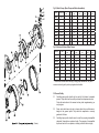
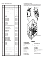
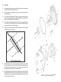
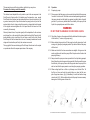
Self-Priming Centrifugal Pumps
& Motor Assemblies
Assembly & Operating Instructions
Model
Serial No.
Engine No.
Year of Manufacture
Unit 8, Hudson Road
Saxby Road Ind. Est.
Melton Mowbray
Leicestershire LE13 1BS
Telephone: +44 (0)1664 567226 Fax: +44 (0)1664 410127
E-mail: [email protected] www.dualpumps.co.uk
CE
793-1100
Appendix 4. A Series Water Pump Service Parts List
NO.
PART NUMBER
1
9907-722-30B
3
9907-765-71
9907-765-72
9907-765-73
4
9907-1262-30B 5
9907-721
7
907-715-10 8
9907-1245-71
9907-1245-72
9907-1245-73
9
9907-1233-30
10
9907-718
11
9907-1302-30
12
9907-1246-71
9907-1246-72
9907-1246-73
13
9907-683-30
14
9907-717-71
9907-717-72
9907-717-73
15
9907-716-10
16
9907-1348-10
17
9907-1009-71
9907-1009-72
9907-1009-73
18 9907-723-30
19
9907-1261-30B
9907-1873-30B
20
9907-720
21
9907-778-11
9907-778-12 9907-778-13 22, 25 & 26
9907-714-11
9907-714-12
9907-714-14
23 9907-1926-71
9907-1926-72 9907-1926-73
26
9907-976-71
9907-976-72
9907-976-73
27
9907-1872-71
9907-1872-72
9907-1872-73 28 9907-1203-71
9907-1203-72
9907-1203-73 29 9907-1303-30
DESCRIPTION
QTY
PLUG, Filler, Black Polyester
1
O-RING, Filler Plug, BUNA-N
1
O-RING, Filler Plug, EPDM (standard)
1
O-RING, Filler Plug, VITON
1
BRACKET, Black Polyester
1
NUT, Plated Steel, 1/4”-20
10
SCREW, 5/16-24 x 1.25” Long, Stainless Steel,
for Pumps close-coupled to engines and cast
pedestal mounted
4
O-RING, Screw Plug, BUNA-N
4
O-RING, Screw Plug, EPDM (standard)
4
O-RING, Screw Plug, VITON
4
PLUG, Screw, Black Polyester
4
KEY, 3/16” Sq. x 15/16” Long, Steel
1
VOLUTE, Rear, Black Polyester
1
O-RING, Segment, BUNA-N
1
O-RING, Segment, EPDM (standard)
1
O-RING, Segment, VITON
1
IMPELLER, Black Polyester 1
O-RING, Screw, BUNA-N
5
O-RING, Screw, EPDM (standard)
5
O-RING, Screw, VITON
5
SCREW, Impeller, 5/16-24 x .75” Long, Stainless Steel 1
SCREW, Volute, #10 x .75”, Stainless Steel
7
O-RING, Drain Plug, BUNA-N
1
O-RING, Drain Plug, EPDM (standard)
1
O-RING, Drain Plug, VITON
1
PLUG, Drain, Black Polyester
1
BODY, 2” NPT, Black Polyester
1
BODY, 2” BSP, Black Polyester
1
SCREW, Body, Plated Steel, 1/4”-20 x 2-3/8”
10
SHIM, Impeller, .006”, Stainless Steel
as required
SHIM, Impeller, .015”, Stainless Steel
as required
SHIM, Impeller, .030”, Stainless Steel
as required
SHAFT SEAL, BUNA-N
1
SHAFT SEAL, EPDM (standard)
1
SHAFT SEAL, VITON
1
O-RING, Body, BUNA-N
1
O-RING, Body, EPDM (standard)
1
O-RING, Body, VITON
1
O-RING, Shaft Seal, BUNA-N
1
O-RING, Shaft Seal, EPDM (standard)
1
O-RING, Shaft Seal, VITON
1
CHECK VALVE, BUNA-N
1
CHECK VALVE, EPDM (standard)
1
CHECK VALVE, VITON
1
O-RING, Rear Volute, BUNA-N 1
O-RING, Rear Volute, EPDM (standard)
1
O-RING, Rear Volute, VITON
1
VOLUTE, Front, Flat, Black Polyester
1
Appendix 4. A Series Water Pump Service Parts List
Dual Pumps Ltd
Self-Priming Centrifugal Pumps
& Motor Assemblies
Assembly and Operating Instructions
These instructions should be kept with the respective pump
unit at all times and referred to as often as necessary.
This manual has been compiled to give all of the necessary
information to allow for the safe installation and operation
of the Dual Pumps Ltd range of Centrifugal Pumps and
Motor Assemblies. Following these simple instructions
will ensure operator safety and prolong the life of the
equipment.
This manual and any other literature supplied should be
read thoroughly before attempting to operate any supplied
unit. Pay particular attention to any instructions given
relating to your personal safety or to the safety of others
who may be in the general area of the operating unit, also
specific instructions relating to the starting and stopping
of petrol and diesel engines.
Our policy is to improve our product continuously and
we therefore reserve the right to change specifications,
models or designs without notice or obligation.
EC DECLARATION OF CONFORMITY
Dual Pumps Ltd
Unit 8, Hudson Road
Saxby Road Ind. Est.
Melton Mowbray
Leicestershire, LE13 1BS
Declares that this equipment conforms to the following directives,
98/37EC, 73/23 EEC, 2000/14/EC.
Name: S Travis
Position: Service Manager.
Signature: ………………..
(A full certificate of conformity can be obtained upon request).
1. Index
Equipment Variants and Options
Section 2
SafetySection 3
Description of Main Features
Section 4
InstallationSection 5
OperationSection 6
MaintenanceSection 7
Fault FindingSection 8
After use storageSection 9
DisposalSection 10
WarrantySection 11
Appendices
Water Pump, service parts list
Appendix 1
Slurry Pump, service parts list
Appendix 2
Fittings and AccessoriesAppendix 3
A Series Water Pump, service parts list
Appendix 4
Appendix 3. Fittings and Accessories
Illustration
Number
1
Part Description
Suction hose, Kanaflex
Delivery hose, Kanaflex
Delivery hose, Layflat
Part Number, 2
inch pump
12-CD20
12-CD20
P3 2LFB
Part number, 3 inch
pump
12-CD30
12-CD30
P48LFB
Quantity
required
Per metre
Per metre
Per metre
9907-733-01
9907-757-90
Each
HB 200P (2in NPT)
HB 300P (3in NPT)
Each
2
Basket foot filter
(water pump)
3
Hose barb
4
Basket foot filter
9907-46286-00
9907-46287-00
Each
5
90 Male adapter
200F-90
9901-SL300-90
Each
6
Hose coupler
200CP
300CP
Each
7
Male adapter
200FP
300FP
Each
8
Sponge gasket
200G
300G
Each
2. Equipment Variants and Options
Special Note
A & S Series Self-Priming Centrifugal Pumps are chemically resistant
for general water service, waste treatment, salt water and many industrial
chemicals.
Moulded from tough glass reinforced thermoplastics, polyester and or
polypropylene to resist corrosion and chemical attack. These pumps feature, as
standard, type 316 Stainless Steel internal hardware and carbon-ceramic
self-lubricating mechanical shaft seals.
Also available with a choice of seals, o-rings and gaskets made from, Viton,
EPDM or Buna-N.
All pumps include a built-in check valve and double flush volute to keep pumps
free of settled solids.
All units are fitted as standard with type 304 stainless steel clips and fasteners.
Manufactured with a choice of either 2” or 3” port diameters, these pumps
handle a wide range of flow and head conditions.
T Series Self-Priming Centrifugal Pumps are lightweight chemically resistant
pumps for general service on water, salt water and mildly corrosive liquids
containing solids. They will pass a solid up to 1/3 the diameter of the suction
port. T Pumps feature a tough non-metallic impeller, steel volute and wear plate
with a non-metallic coating, type 316 stainless steel body-clamp, and a housing
made from rugged glass reinforced polyester.
The pumps also feature a pressurised oil lubrication system, which protects the
hard silicone carbide shaft seal. o-rings and gaskets are made from Buna-N.
All pumps feature a built-in check valve, easy servicing and a self-cleaning
double flush volute to keep pumps free of settled solids.
Safety Warning
Verify the chemical compatibility of the liquid you wish to pump with the materials
your pump is made from. If you are unsure of the compatibility please contact
your local dealer or the service department of Dual Pumps Ltd. Do not use a
pump that is chemically incompatible with the liquid you intend to pump. Material
failures in pumps caused by chemical incompatibility can cause incidents, which
in turn could lead to serious personal injury or even death. Such incidents can
also cause serious environmental damage.
This manual deals specifically with the A, S and T type variants of the Dual
Pumps Ltd product range.
Power input
Petrol and Diesel engines, 4 BHP - 8 BHP.
Electrical drives, 240 – 415 volts.
Pump types
Centrifugal 2” inch and 3” inch ports
23 – 36 metres max head.
Transport frame
Pumps are housed in rigid steel frames in
either static or wheeled options.
NB: Pumps supplied as bare motor and pump assemblies have no
Transport frame.
Max
Head
Metre
Max
SG
Weight
Kg**
Dimensions
LxWxH
*SPL
LwA
dB
*GSPL
LwA
dB
Group
604
23
1.0
19
495x345x460
101
111
1-A
2
604
23
1.0
20
576x520x476
100
111
1-Q
Petrol
4 bhp
2
568
30
1.3
25
576x520x476
98
111
1-B
DPF25P
Petrol
5.5 bhp
2
870
25
1.8
25
576x520x476
107
111
1-C
DPF26P
Petrol
5.5 bhp
2
757
36
1.2
25
576x520x476
107
111
1-C
DPF35P
Petrol
5.5 bhp
3
984
25
1.8
27
576x520x476
107
111
1-C
DPF25D
Diesel
6.8 bhp
2
870
25
1.8
50
660x445x560
109
115
2-J
DPF26D
Diesel
6.8 bhp
2
757
36
1.2
50
660x445x560
109
115
2-J
DPF35D
Diesel
6.8 bhp
3
984
25
1.8
50
660x445x560
109
115
2-J
DPF2TP
Petrol
5.5 bhp
2
795
27
-
39
650x445x660
107
111
1-C
DPF3TP
Petrol
8 bhp
3
1362
24
-
65
1060x620x650
105
111
1-E
DPF2TD
Diesel
6.8 bhp
2
795
27
-
71
1060x620x650
109
115
2-J
DPF3TD
Diesel
6.8 bhp
3
1362
24
-
78
1060x620x650
109
115
2-J
Ports Flow
(Inch) L.p.m
Drive
DPFA200
Petrol
4 bhp
2
DPFE3
Petrol
3.5 bhp
DPF24P
Illustration
Number
Part
Description
Part Number,
2 inch pump
Part number,
3 inch pump
Quantity
required
1
2
3
4
5
6
Filler plug, oil lube
O ring
Lube retainer
Tube
Filler plug, water
Pump back plate assembly,
(bracket) (Includes items 3 & 4)
O ring
Washer (diesel only)
Screw, Petrol
Screw, Diesel
Oil lip seal
O ring, shaft seal
Mechanical seal set
O ring, Volute
Volute
Impeller shim
Shaft key
Volute screw
Impeller
O ring
9907-722-30A
765-71
9907-46294-30
9907-46215-71
9907-722-30B
46218-31
9907-722-30A
765-71
9907-46294-30
9907-46215-71
9907-722-30B
46218-31B
1
2
1
1
1
1
717-71
9919-3005
715-10
9919-6001
46314-11
976-71
46250-11
1203-71
46224-80
778-12
46339
462269
46229-80
46291-71
46303-71
9919-3005
715-10
9919-6001
46313-11
46307-71
46251-11
46292-71
46204-80
46338-10
46278
462269
46214-80
46290-71
4
4
4
4
1
1
1
1
1
As reqd’
1
4
1
1
46341
715-10
46225-91
46206-71
1348-10
46344-30
46217-71
46304-71
46252-31A
-46309-10
46205-91
46206-71
1348-10
46344-30
46217-71
46304-71
46207-31B
1
1
1
1
2
1
1
1
1
1009-71
723-30
46305-10
1009-71
723-30
46305-10
1
1
1
7
8
9
Fig 1, Centrifugal Pumps, A, S and T series.
Model No
Appendix 2. Slurry pump service parts list
*SPL = Sound Power Level on equipment representative of this type.
*GSPL = Guaranteed Sound Power Level for this equipment.
10
11
12
13
14
15
16
17
18
19
20
21
22
23
24
25
26
27
28
29
30
31
Washer
Impeller screw
Wear Plate
Suction gasket
Check valve retainer screw
Check valve retainer
Check valve
O ring, Body
Pump body assembly
(Includes items 24, 25 & 26)
O ring drain plug
Drain plug
Body clamp
Fig 2, Water Pumps, (Bare Pump and Motor Assemblies)
Part No
Engine Type
Port Size
inch
BHP
Max Flow
Lpm
Max Pressure
bar
Fuel
Type
Weight
Kg**
Max
SG
200PDL
Lombardini
2
6.8
871
2.5
Diesel
42
1.9
207PDL
Lombardini
2
6.8
757
4
Diesel
42
1.2
300PDL
Lombardini
3
6.8
1060
2.5
Diesel
44
1.8
200PPV-5
Honda
2
5.5
871
2.5
Petrol
19
1.5
200PPVDL
Lombardini
2
6.8
871
2.5
Diesel
42
1.5
207P-3
Honda
2
4
568
3
Petrol
17
1.2
200P-5
Honda
2
5.5
871
2.5
Petrol
19
1.9
207P-5
Honda
2
5.5
757
4
Petrol
19
1.2
300P-5
Honda
3
5.5
1060
2.5
Petrol
20
1.8
Fig 3, Electrically Driven Water Pumps
Part No
Volts
Ports
inch
BHP
Max Flow
Lpm
Max Pressure
bar
Weight
Kg**
Max
SG
207P-ES3
240
2
3
504
2.4
23
1.3
200P-ES3
240
2
3
756
1.5
23
1.8
207P-ET3
415
2
3
504
2.4
23
1.3
200P-ET3
415
2
3
756
1.5
23
1.8
200P-ET5
415
2
5.5
756
1.5
31
1.8
207P-ET5
415
2
5.5
725
2.5
31
1.3
300P-ET5
415
3
5.5
880
1.5
32
1.8
200PP-ET5
415
2
5.5
756
1.5
31
1.5
** Care should be taken when moving or lifting pump assemblies, they have
uneven centres of gravity and may topple when handled.
3.0 General Safety
3.1 Centrifugal pump units should only be used by fully trained, competent
persons. They should not be used by untrained or inexperienced users.
Follow the instructions in this manual and any other supplementary you
may be given.
3.2 Pump units should never be set in places where they could become a
danger to the general public. They should be supervised or securely
guarded at all times.
(T Series)
3.3 Centrifugal pump units should never be used for pumping incompatible
chemicals, flammable or explosive liquids. The pumping of incompatible
liquids can lead to fire or explosion, resulting in death or serious injury.
3.4 Never operate pump units in a confined space or an explosive atmosphere,
the charging and discharging of fuel tanks is forbidden unless the area is
well ventilated.
3.5 Always site pumps on firm level ground. Vibration caused during the
pumping operation may cause the pump to move. Assess any possible
danger associated with this and if necessary tether the unit to a solid
post.
3.6 Never operate any equipment with the guards removed.
3.7 Ensure that the pumps drive motor is isolated before working on the pump
unit. Petrol and diesel engines should be immobilised so they can- not
start. Electric motors should be isolated, by removing fuses.
Only competent, authorised persons should be allowed to work on electrical
installations. The unit should be declared safe before proceeding with any
required service.
Illustration
Number
3.10 Protective clothing. Operators and assistants should assess the local
hazards associated with the liquid being pumped. The recommended
protective clothing as prescribed by COSHH and any other method of
hazard analysis should by worn at all times during the installation, pumping
and servicing operations.
Part
Number
Quantity
Required
16
Check valve, Buna *
Check valve, EPDM *
Check valve, Viton *
9907-705-71
9907-705-72
9907-705-73
1
1
1
17
Pump body, 2 inch Polyester (black)
Pump body, 2 inch Polypropylene (grey)
Pump body, 3 inch Polyester (black)
9907-1002-30
9907-1002-40
9907-755-30
1
1
1
18
Drain plug, Polyester (black)
Drain plug, Polypropylene (grey)
9907-723-30
9907-723-40
1
1
19
O ring, Buna *
O ring, EPDM *
O ring, Viton *
9907-1009-71
9907-1009-72
9907-1009-73
1
1
1
20
Filler plug, Polyester (black)
Filler plug, Polypropylene (grey)
9907-722-30B
9907-722-40
1
1
21
O ring, Buna *
O ring, EPDM *
O ring, Viton *
9907-765-71
9907-765-72
9907-765-73
1
1
1
22
Body screw, Polypropylene pump, Stainless steel.
Body screw, Polyester pump, Zinc plated.
9907-720-10
9907-720
10
10
23
Body nut, Stainless steel.
Body nut, Zinc plated.
9907-721-10
9907-721
10
10
3.8 Do not apply any heat to a Pump and Motor installation.
3.9 The pump body should not be subjected to any internal pressure greater
than 4.5 bar, (65 psi). Over pressurisation may be caused by pump shaft
speeds of more than 3600 rpm, the quick closing of discharge valves,
running over discharge hoses, flooded suctions with a high positive
pressure, or the pumping of liquids with a specific gravity, (SG) greater
than recommended. (see figs 1,2 and 3).
Description
* Polyester pump (black) standard EPDM buna & viton options
* Polypropylene (grey) standard viton, buna EPDM options
Appendix 1. Water pump service parts list.
Illustration
Number
Description
Fig 4, Description of main features
Part
Number
Quantity
Required
1
Pump back plate (bracket), Polyester (black)
Pump back plate (bracket), Polypropylene (grey)
9907-703-30
9907-703-40
1
1
2
Plug (Viton pumps only)
9907-750-40
4
3
Back plate screw (bracket screw), stainless steel.
9907-715010
4
4
O Ring, Buna *
O Ring, EPDM *
O Ring, Viton *
9907-717-71
9907-717-72
9907-717-73
4
4
4
5
O Ring shaft seal, Buna *
O Ring shaft seal, EPDM *
O Ring shaft seal, Viton *
9907-976-71
9907-976-72
9907-976-73
1
1
1
6
Shaft seal, Buna *
Shaft seal, EPDM *
Shaft seal, Viton *
(NB: Item 5 is included in the shaft seal kit, item 6).
9907-714-11
9907-714-12
9907-714-14
1
1
1
7
Shaft impeller key, Mild steel
Shaft impeller key, Stainless steel
9907-0718
9907-0718-10
1
1
8
O ring segment, Buna *
O ring segment, EPDM *
O ring segment, Viton *
9907-754-71
9907-754-72
9907-754-73
1
1
1
9
O ring body, Buna *
O ring body, EPDM *
O ring body, Viton *
9907-719-71
9907-719-72
9907-719-73
1
1
1
10
Impeller (704), Polyester (black)
Impeller (706), Polyester (black)
Impeller (975), Polyester (black)
Impeller (975), Polypropylene (grey)
9907-704-30
9907-706-40
9907-975-30
9907-975-40
1
1
1
1
11
O ring, Buna *
O ring, EPDM *
O ring, Viton *
9907-717-71
9907-717-72
9907-717-73
1
1
1
12
Impeller screw, Stainless steel.
9907-716-10
1
13
Volute, for 704 & 706 impeller, polyester, standard
Volute, for 975 impeller, polyester, standard
Volute, for 975 impeller, Ryton, polypropylene pump
9907-702-30
9907-977-30
9907-977-60
1
1
1
14
Volute screw, stainless steel, self tapping
9907-725-10
2
15
Volute top screw, for 977 volute
Volute top screw, for 702 volute
9907-997-10
9907-771-10
1
1
(The drive engine illustrated in fig 4 is a petrol version, for diesel engines refer to the engine
manufacturers handbook) Electric motors refer to wiring diagram in the motor terminal box.
Note: Typical pump layout
List of main features
1. Typical transport frame
(NB: Wheels are fitted to some models)
2. Drive engine
3. Pump assembly
4. Inlet port (suction)
5. Outlet port (pressure)
6. Drain plug
7. Priming port
8. Engine oil dipstick
9. Engine oil drain plug
10. Engine speed control
11. Engine cold start
12. Pull starter
13. Fuel tank filler
Slurry pump (see detail drawing)
14. Mechanical seal lubricator
15. Drain plug
16. Removable body clamp
5.0 Installation
5.1 Fill the engine with the necessary oil and fuel. Refer to engine manufacturers
handbook for recommended oils and fuels.
5.2 Place the battery in the battery box and connect the power leads. (Electric
start models only).
5.3 Screw the Inlet and Outlet Quick Release Couplings into their respective
ports. Do not over tighten the screw thread. Fittings that are inserted into
plastic pump bodies should be hand tight only.
5.4 When pumps are installed into permanent situations using solid pipe work
use at least 0.3m of flexible pipe on the suction and discharge ports to
reduce the possibility of vibration damage.
5.5 Long suction and delivery hoses should be supported to reduce possible
stress damage to the pump body.
5.6 If flexible hoses are to be laid across roadways ensure they are protected
by ramps, planks etc. (see fig 5). Vehicles running across hoses not only
damage the hose but also will send shock waves into the pump body,
causing mechanical damage or over pressurisation.
5.7 Electrically driven pumps should only be installed by a qualified Electrical
Engineer. Electric motors refer to the wiring diagram in the motor terminal
box. (Ensure the motor is wired for anti-clockwise rotation as you look at
the pump impeller or inlet port).
(S Series)
This warranty does not affect any statutory rights that you may have.
Procedure for claiming under this warranty
6.0 Operation
The claimant must despatch the unit, product or part at his own expense to the
Dual Pumps Ltd factory with a full detailed report for inspection, upon receipt
Dual Pumps Ltd will inspect and decide whether the unit, product or part is in fact
a genuine warranty claim. Upon this decision the pump, product or part will be
replaced either free of charge under this warranty or despatched and charged
to the original customer together with a full report should it be found not to be
covered by this warranty.
6.1.1 Please ensure that the pump you have selected is suitable for the purpose
for which it is to be used. Check the maximum head/operating pressure of
the pump selected and the liquid type against a suitable table of specific
gravities. If you have any doubts about the suitability of the pump for the
liquid to be pumped please seek further advice.
Warranty claimed items, if required urgently will be despatched to the customer
and charged for, on the receipt of the claimed defective item Dual Pumps Ltd will
decide whether a claim is valid and if so will issue a credit for the item. Should
Dual Pumps Ltd find the claimed item to be out of warranty declarations the said
charge will stand and be paid for by the customer as normal.
The copyright of this manual belongs to Dual Pumps Ltd and must not be copied
or reproduced without the express permission of the company.
6.1 Preparing to pump
WARNING
DO NOT PUMP FLAMMABLE OR EXPLOSIVE LIQUIDS.
6.1.2 Check the oil levels on the engine and that the shaft seal lubrication system
is filled with oil. (T series, slurry pumps only).
6.1.3 Before starting the pump drive fill the pump body with clean water. Avoid
running a dry pump for prolonged periods. Dry seals will fail and the pump
will then leak.
6.1.4 Make sure that all of the hose connections are airtight. Air ingress on the
suction port/hose will make the pump difficult to prime and will reduce the
pumping efficiency.
6.1.5 Always locate the pump as close as possible to the liquid being pumped,
this will keep the suction hose as short as possible. Short hoses will improve
the efficiency of the pump. Ensure that the ground under the pump is firm
and level and that the pump cannot move during the pumping operation.
6.1.6 When sucking liquid from a ditch or a pit always use a Suction Filter. Tie
the filter so it does not touch the muddy bottom, or place the filter on a
pile of large clean stones, (fig 6). Alternatively it can be tied inside a large
clean bucket, (fig 7). Both methods will protect the pump from unnecessary
damage due to the ingress of stones etc.
6.2 Pumping
6.2.1 Start the drive motor. Refer to the accompanying literature, which relates
to the specific type of drive motor fitted.
6.2.2 Open all suction and delivery valves. The unit should now be pumping as
required. If you experience any problem in the pumping operation refer to
section 8, Fault Finding.
6.3 General
6.3.1 Do not run the pump for prolonged periods with the delivery line closed
or restricted, this will cause the pumped liquid to overheat damaging the
pump and in extreme cases explosion.
6.3.2 After use, drain and clean (internally and externally) the pump body and
the attaching hoses. In frosty weather additional protection should be given
to the pump and its hoses to protect them from frost damage.
7.0 Maintenance
7.1 Routine maintenance
Maintenance activity
Inspect / top up oil levels
a) Engine b) Pump seal lubricator (T series only)
Clean water inlet and suction line filters
Inspect the suction and pressure hoses and their respective connections for
damage and air tightness.
Pneumatic tyres, where fitted. Check for wear, damage and abrasion. Check
tyre pressures inflate to 0.7 bar, (10 PSI).
Change engine oil, only replace the oil with one recommended by the
manufacturer. See supplementary literature.
7.2 Frequency
Each and every
use.
Each and every
use.
Each and every
use.
Check weekly
Change as
recommended
by the engines
manufacturer
Replacing pump seals, water pump (S series & A series)
(NB: Refer to the illustrations in appendix 1 & 4 to assist with re-assembly).
7.2.1 Ensure that the pump body is washed out and drained.
7.2.2 Unscrew and remove the body screws (22) S Series (20) A Series and
split the pump body by pulling the pump body forwards.
7.2.3 Next remove the volute by unscrewing and removing the self-tapping
screws (14, 15) S Series (16) A Series.
Neither this warranty or any implied warranty apply to damage caused by any of
the following:
1. Freight damage.
2. Frost or freezing damage.
3. Damage caused by parts and/or accessories or components not obtained
from or approved by Dual Pumps Ltd.
4. Any consequential or incidental damage arising from the use of any pump or
other products supplied by Dual Pumps Ltd.
5. Damage caused by misapplication and/or misuse. The normal wear of moving
parts or components affected by moving parts.
The liability of Dual Pumps Ltd under the foregoing warranty is limited to the
repair or replacement at Dual Pumps Ltd option without charge for labour,
mileage costs or materials of any parts upon return of the entire pump or other
product or of the particular part to the Dual Pumps Ltd factory within the warranty
period at the sole expense of the purchaser, which part shall upon examination
appear to Dual Pumps Ltd satisfaction to have been defective in material or
workmanship.
The liability of Dual Pumps Ltd under any theory or recovery (except any express
warranty where the remedy is set forth in the above paragraph) for loss, harm
or damage, shall be limited to the lesser of the actual cost, harm or damage,
or the purchase price of the involved pump or other product when sold by Dual
Pumps Ltd to its customers. Dual Pumps Ltd expressly warrants its pumps and
other products as above stated. There are no other express warranties. Any
implied warranties, including implied warranty of merchantability or of fitness for
a particular purpose, are limited to twelve (12) months from the date of purchase
by the original purchaser, (six (6) months for the equipment on hire or rental).
There is no implied warranty of fitness for a particular purpose or merchantability
when this product is put to rental use.
No person including any dealer or representative of Dual Pumps Ltd is authorised
to make any representations or warranty concerning Dual Pumps Ltd products
on behalf of Dual Pumps Ltd, or to assume for Dual Pumps Ltd the obligations
contained in this warranty. Dual Pumps Ltd reserves the right to make changes in
design and other changes and improvements upon its products without imposing
and obligations on itself to install the same, in its existing products or products
then in the process of manufacture.
9.0 After use storage
9.1 Disconnect the suction and pressure hoses rinsing clean and allow to dry.
9.2 Flush the pump body with clean water, drain by removing the drain plugs.
Replace plugs when completely drained. Remove dirt from exterior of
pump.
9.3 Ensure the pump is clean and dry before storage, store in a dry frost proof
place.
10.0 Disposal
10.1 At the end of its useful life this pump unit must be disposed of in a responsible
manner following any specific requirements of the local authority in which
the pump unit is located.
10.2 Drain any unused fuel from the fuel tank and the residual engine and
lubricating oils. Dispose of these oils in a manner, which is acceptable to
your local authority.
Do not dispose of by allowing them to drain into a sewer or watercourse or
pollute land.
10.3 Remove the plastic components, dispose of by recycling or in general
refuse whichever is the locally approved manner.
10.4 Metallic parts should be sent for recycling via an approved metal
merchant.
10.5 Any fitted tyres should be removed from their rims and sent for recycling
via an approved contractor.
11.0 Warranty
Dual Pumps Ltd as suppliers warrants to the original purchaser, each new unit
or other product supplied from its factory, for a period of twelve (12) months from
the date of shipment from the factory, six (6) months for equipment on hire or
rental, to be free from defects in material and workmanship under normal use
and service. “ Normal use and service” means not to exceed recommendations
on maximum speeds, pressures and temperatures or handling fluids which are
not compatible, as noted in the applicable Dual Pumps Ltd catalogue, technical
literature and instructions. This warranty shall not apply to any pump or other
product, which has been repaired or altered, to adversely affect the performance
or reliability of the pump or product. Tools or hoses are not covered by this
warranty due to the adverse conditions of their use.
7.2.4 Unscrew the central impeller screw and pull the impeller off of its drive
shaft. In some older installations it my not be possible to remove the
impeller without damaging it.
7.2.5 Remove the bracket screws (3) S Series (7) A Series. In grey polypropylene
pumps these are covered by plastic sealing plugs, which will require
drilling out.
7.2.6. Remove the pump backing plate and gently drift out the old static seal.
Take care not to damage the backing plate or when the new seal is fitted
a leak free installation may not be possible and a new backing plate may
be required.
7.2.7 Refit the new static seal. Ensure the o-ring is fitted onto the steel cup. Use
a hollow drift (a socket is suitable) that goes over the ceramic face and
rests on the steel lip.
7.2.8 Assemble the rotating part of the seal into the back of the impeller. Press
the seal in gently by hand, do not use excessive force or any tool, which
could cause damage. Check that the face of the seal is smooth, should it
have a recess remove the rubber boot and reverse the seal.
Do not fit a seal that shows any sign of damage. Damaged seals will
leak.
7.2.9 Reassemble the pump by following steps 7.2.6 to 7.2.2 in reverse order.
Do not forget to insert the drive key.
Useful hints and points to note;
Strip the pump completely before ordering any new parts, replace any
damaged parts along with worn.
You are advised to always replace the o-ring on the impeller and the
screws holding the pump backing plate together with the plastic sealing
caps. Use Loctite or a similar product on the pump backing plate screws
and the impeller screw.
7.3 Replacing pump seals, slurry pump (T series)
(Refer to the illustration in appendix 2 to assist with re-assembly).
7.3.1 Ensure that, the pump body is washed out and then drained.
7.3.2 Remove the quick release metal strap holding the two parts of the pump
body. Draw the loosened pump body towards you away from the pump
backing plate.
7.3.3 Remove the large o-ring.
7.3.4 Remove the black wear plate. This will expose the volute and the
impeller.
7.3.5 Remove the impeller by unscrewing the central screw. Inserting a M10
bolt into the central hole. Turn the screw clockwise to draw the impeller
off the drive shaft.
7.3.6 Remove the volute by unscrewing 2 x M6 screws (4 screws in 3 inch
pump).
7.3.7 Undo and remove the four screws holding the pump backing plate. Pull
the plate forwards over the drive shaft. Remove the drive key first.
8.0. Fault Finding
Symptom
Probable causes?.
Corrective actions
Pump will not prime or retain
prime after operation.
Air leak in suction line.
Clogged valve or strainer
Replace or repair
Clean or replace
Flow rate is low
Incorrect speed
Inlet / outlet pipes are clogged
or damaged
Clogged or worn impeller
Outlet pipe is restricted or
undersized
High pressure in the outlet
pipe.
Check drive speed
Clean or replace
Faulty suction pipe
Pump is located too far from
the liquid being pumped
Inlet / outlet valves closed
Clogged inlet strainer
Valves clogged
Discharge height is too great
Suction lift is too great.
Replace
Relocate
Liquid drips from the point
where the drive shaft enters
the pump backing plate, when
the pump is full of liquid.
Damaged seal assembly
Replace seals see section 7
The pump starts and stops
pumping.
Fouled impeller
Faulty mechanical seal
Leak in the suction hose
Leak in the suction valve
Leak in the suction connection
Clean
Replace seals see section 7
Repair or replace
Repair or replace
Repair or replace
Excessive noise while the
pump is in operation.
Pump not secured to firm
foundation
Piping not supported to
relieve any strain on the pump
assembly
Restricted suction line
Cavitation.
Secure properly
7.3.8 Remove the static seal and the o-ring from the backing plate and the
rotating seal from the back of the impeller.
7.3.9 On re-assembly repeat steps 7.3.8 to 7.3.2 in reverse order.
7.3.10 Take care not to damage the faces of the seal kit and the oil seal upon
reassembly.
7.3.11 Shim the impeller until the back of the impeller and the front of the volute
are just clear. The shims are inserted into the back of the impeller.
Pump runs but there is no fluid
7.3 12 The wear plate is assembled onto the lugs on the front of the volute with
the indicator arrows pointing upwards. Check for free movement of the
pump by turning the pump by hand.
Useful hints and points to note;
Strip the pump completely before ordering any new parts, replace any
damaged parts along with the worn.
You are advised to always replace the o-ring on the impeller and the
screws holding the pump backing.
Use Loctite or a similar product on the pump backing plate screws and
the impeller screw.
Clean or replace
Flush out piping and or replace
Check and reduce pressure
Clean or replace
Clean or replace
Clean or replace
Reduce the height
Lower the pump
Support piping
Clean and or replace
A Reduce pump speed
B Increase the size of the inlet
C Viscosity of pumped material
too high.