Transcript
Paper size: A4 297x210
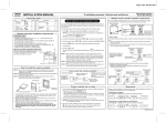
INSTALLATION MANUAL
Wired remote controller
Model: RBC-AMT31E, RBC-AMT32E, NRC-01HE
To installation personnel - Electrical work and Service
The indoor units described in this Installation Manual represent air conditioners, air to air heat exchanger with direct expansion coil (& humidifier), or air to air heat exchanger.
Accessory parts
No.
Part Name
Remote
1 controller
Screw
2 M4 x 20 mm
Requirements when installing two remote controllers
Q'ty
No.
Q'ty
1
3
2
2
Installation
4 Manual
1
Part Name
Wood screws
In a dual remote controller system, one or more units are operated by multiple
remote controllers. (A maximum of two remote controllers can be set.)
How to select the room temperature sensor
Two room temperature sensors are installed: one in the indoor unit; the other in
the remote controller. Only one sensor (usually the indoor unit’s) can be active at
any one time. (Not available for a air to air heat exchanger.)
Remote controller
(inside, rear)
Header remote Follower remote
controller
controller
To select the sensor in the remote controller, perform the following steps.
1. Push
Remote controller installation requirements
• Install the remote controller 1 m - 1.5 m above floor level (average room
temperature area).
• Do not install the remote controller in a place exposed to direct sunlight or
outside air (such as a window, etc.).
• Do not install the remote controller where ventilation is poor.
• Do not install the remote controller in a freezing or refrigerated area - the
remote controller is not water or splash-proof.
• Install the remote controller in a vertical position.
2. Using the temperature setup buttons
3. Using the timer buttons
62
84
120
For air to air heat exchanger
RBC-AMT31E or RBC-AMT32E is not
available for the systems equipped with the
air to air heat exchanger(s) only.
, specify the item code
, change the setting from
.
to
.
constantly lit.)
18
(Fig. 1)
/
/
mm
How to install the remote controller
NOTE 1: The remote controller wire should not be bundled with other wires
(mains, etc.), or installed with other wires in the same conduit, as
malfunction may result.
NOTE 2: Install the remote controller away from sources of electrical interference
and electromagnetic fields.
NOTE 3: If electrical interference is unavoidable, countermeasures such as
appropriate filtering should be employed.
Wiring slot
Wood screws
5. Push the
button.
The status returns to the operation stop status and
LCD.
<Remote controller (Rear)>
Remote controller
Cover
1. For removal of the remote controller’s lower case (rear case), insert the tip of
a straight blade screwdriver, etc., into the two openings at the bottom of the
remote controller to open the lower case.
2. Fix the remote controller’s rear case by wood screws (2 pcs.). Do not over
tighten, as it may damage the rear case.
3. Connect the wires from the indoor unit to the remote controller terminal block.
(Refer to “How to wire the remote controller”.)
Connect the wires of the remote controller following the terminal
numbering convention of the indoor unit to prevent miswiring. (Do not
apply AC 230V mains voltage to the remote controller as it will be
damaged).
2
1
2
1
2
1
2
DIP switch
Remote controller Remote controller
(Header)
(Follower)
is displayed in the
NOTE 1: When using two remote controllers, the room temperature sensor
selection can be set either from the header/follower remote controller.
Only the header remote controller can act as a remote control sensor.
When using two remote controllers, the temperature can be set from
either the header or follower remote controller.
NOTE 2: In group control, the remote control sensor does not work if the group
address is not set to the indoor unit of the master unit.
NOTE 3: When using the remote sensor and the remote controller together, do
not use the remote control sensor of the remote controller.
• Operating one indoor unit
from remote controllers
installed in two different
locations.
A B
A B
Remote controller
wires
(locally procured).
Terminal block for
remote controller wiring
A B
Indoor unit
Ground
• Operating a group control of multiple indoor units from remote controllers
installed in two different locations.
* Header and Follower remote controllers are operable even if they are
connected to any indoor unit.
Remote controller
(Header)
Remote controller
(Follower)
How to wire the remote controller
• Connection diagram
Terminal block
for remote
controller wiring
in indoor unit
* Use 0.5 to 2.0 mm2 wire
* Can not use the closed end
wire joint.
Remote controller wiring
(locally procured)
A
A
B
B
Be sure to set
switch 2 to the
lower position.
• How to install
For a dual remote controller system, install the remote controllers in the following
way.
1. Set one of remote controllers as the header remote controller. (The default
setting is ‘Header.’)
2. Set the DIP switch on all other remote controller P.C. boards to Sub (to enable
them as follower remote controllers).
Remote controller inter-unit wires
for group control
(locally procured)
A B
A B
Indoor unit
No.1
Remote controller
Remote controller
terminal block
Ground
A B
Indoor unit
No.2
Ground
Remote controller test run setup
1. Push and hold the
button for 4 seconds or more until “TEST” appears in
ON/OFF button.
the LCD, then press the
• “TEST” appears in LCD during the test run.
• Temperature adjustment is not possible while “TEST” is displayed. The test
run applies considerable load on the machine; therefore, it is recommended
not to use the test mode beyond necessity.
2. The test mode should be used in either HEAT or COOL mode.
NOTE: The outdoor unit will not operate for approx. 3 minutes after power up,
or the operation will stop.
3. Be sure the “TEST” indication in the LCD has disappeared by pushing the
button again after exiting the test mode. (The remote controller has a
60-minute off timer function to prevent continuous test run).
A B
Terminal block for
remote controller
wire
* Terminals A and B are non-polar.
Lower case
(Rear case)
1
DIP switch
4. Push the SET button. (The display should stop flashing and become
Remote controller installation dimension
Be sure to follow the installation dimension
as shown in the figure 1 when you install
the remote controller on the wall.
for 4 seconds or more.
NOTE: The unit number displayed the first time is the indoor unit address of
the master unit in the group control.
NOTE: Do not press the UNIT button.
Installation place
120
+ temperature setup button
Follower remote
controller
Header remote
controller
A B
Indoor unit
No.3
Ground
A B
Indoor unit
No.8
Ground
Requirement
When a remote controller is used for the first time, initial operation after power on
will take a few moments. This is not a malfunction.
<Initial power on period>
Allow approx. 5 minutes for the remote controller to operate.
Power on
“SETTING”
flashing
Approx.
5 minutes
“SETTING”
off
Complete
<Usual power on period after the second time>
Allow approx. 1 minute for the remote controller to operate.
Power on
“SETTING”
flashing
Approx.
1 minute
“SETTING”
off
Complete
ET9X463201 (EN)
