1
INSTALLATION AND OPERATING
INSTRUCTIONS
Code: 05 MT MX15 GB01
Warnings
Read these instructions carefully before installation and start-up particularly to ensure
compliance with the instructions regarding the safety of the equipment in respect to the
intermediary or final user.
The electrical installation and connections should be performed by qualified personnel in
accordance with the manufacturer instructions and the standards of competent authorities in
the industry.
Non-compliance with the instructions may have a serious impact on people’s safety. Strict
compliance is required particularly for electrical installation and assembly (connections,
service lines).
Any modification of the equipment as well as use of unauthorized parts will result in
cancellation of any warranty.
The control unit is designed to be used for specific purposes that are indicated in the
technical specifications. It is not authorized to exceed the specified values in any case.
This document is not contractually binding. In the interests of its customers, INDUSTRIAL
SCIENTIFIC CORPORATION reserves the right to modify the technical specifications of
its equipment without notice in order to improve its performance.
Warning Signs
Operating ground terminal
Attention! Risk of electric shock.
Attention (see accompanying documents)
3
INDUSTRIAL SCIENTIFIC
CORPORATION
GAS DETECTION AND DUST ANALYSIS
Thank you for choosing an INDUSTRIAL SCIENTIFIC CORPORATION unit.
We have taken all the required measures to guarantee that our equipment meets your expectations.
It is important now that you carefully read the following document.
LIMITATIONS OF LIABILITY
* INDUSTRIAL SCIENTIFIC CORPORATION disclaims responsibility towards any individual for
damage to the equipment, physical injury or death resulting fully or partially from inappropriate use, and/or
installation or storage of equipment that does not comply with the instructions and warnings and/or with
existing standards and regulation.
* INDUSTRIAL SCIENTIFIC CORPORATION does not support or authorize any other company or
individual to assume the share of liability of INDUSTRIAL SCIENTIFIC CORPORATION, although it
may be involved in the sale of products manufactured by INDUSTRIAL SCIENTIFIC CORPORATION
* INDUSTRIAL SCIENTIFIC CORPORATION shall not be liable for direct and indirect losses as well
as direct and indirect damages resulting from the sale and use of all its products IF THESE PRODUCTS
HAVE NOT BEEN DEFINED AND SELECTED BY INDUSTRIAL SCIENTIFIC CORPORATION
FOR THE PURPOSE THAT THE BUYER USES THEM.
CLAUSES REGARDING OWNERSHIP
* The drawings, plans, specifications and information included in this document contain confidential
information that is the property of INDUSTRIAL SCIENTIFIC CORPORATION.
* This information may not be reproduced, copied, divulged, partially or fully, by physical, electronical or
any other means, nor used as the basis for the manufacture or sale of INDUSTRIAL SCIENTIFIC
CORPORATION equipment or for any other reasons without prior consent from INDUSTRIAL
SCIENTIFIC CORPORATION
WARNINGS
* This document is not contractually binding. In the interest of its customers, INDUSTRIAL SCIENTIFIC
CORPORATION reserves the right to modify the technical specifications of its equipment without notice
in order to improve its performance.
* CAREFULLY READ THE MANUAL BEFORE FIRST USE OF THE EQUIPMENT: this manual
must be read by any individual who is or will be responsible for using, maintaining or repairing this
equipment.
* This equipment will only provide the stated performance levels if it is used, maintained and repaired
in accordance with the directives of INDUSTRIAL SCIENTIFIC CORPORATION, by
INDUSTRIAL SCIENTIFIC personnel or personnel approved by INDUSTRIAL SCIENTIFIC
CORPORATION
WARRANTY
* Two-year warranty under normal conditions of use for parts and labor (return to our shop), except for
consumables (sensors, filters, etc.).
4
Table of contents
I.
PRESENTATION............................................................................................................7
II.
TECHNICAL SPECIFICATIONS................................................................................7
1.
CHARACTERISTICS .............................................................................................................7
III.
DETAIL SPECIFICATIONS FOR USE IN COMBUSTIBLE ATMOSPHERES
IN ACCORDANCE WITH THE ATEX 94/9/CE EUROPEAN DIRECTIVE. ........9
1.
SPECIFICATIONS FOR MECHANICAL AND ELECTRICAL INSTALLATION IN CLASSIFIED
ZONE. .................................................................................................................................9
2.
METROLOGICAL SPECIFICATIONS .....................................................................................10
3. CONNECTION OF DETECTORS OTHER THAN INDUSTRIAL SCIENTIFIC ON THE
MX15 CONTROL UNIT ...............................................................................................................10
3.1. Transfer curves of control unit in configuration 0 at 100% LEL...........................10
3.2. Power supply and load resistance characteristics ..................................................11
4.
MARKING .........................................................................................................................11
IV.
CONTROL UNIT INSTALLATION ..........................................................................11
1.
CONTROL UNIT MOUNTING ...............................................................................................11
2.
CONTROL UNIT ELECTRICAL CONNECTIONS ......................................................................11
2.1. Protective ground ...................................................................................................11
2.2. Power supply..........................................................................................................12
2.2.1. Power supply 230 Volts (115VAC on request) ...............................................12
2.2.2. Power supply 24 VDC (protection through F8) can be connected
on terminals marked 0 and +24V, as indicated in the wiring
examples at the end of the manual..................................................................12
2.3. CONNECTIONS ...................................................................................................12
2.3.1. Sensors ............................................................................................................12
2.3.2. Alarm relays ....................................................................................................13
2.3.3. Fault relays .....................................................................................................13
2.3.4. Remote acknowledgment .................................................................................13
V.
OPERATING INSTRUCTIONS .................................................................................14
1.
INSTRUCTIONS ON THE DISPLAY UNIT UPON ACTIVATION: ................................................14
1.1. Sensor display ........................................................................................................14
2.
MENUS .............................................................................................................................14
2.1. Menu viewing ........................................................................................................14
2.2. Menu selection .......................................................................................................15
5
2.3.
2.4.
2.5.
2.6.
2.7.
2.8.
To exit while viewing a menu (ECHAP) ...............................................................15
Programming Menu ...............................................................................................15
Initialization Menu (INI)- Start-up ........................................................................16
Code (access) Menu ...............................................................................................16
Buzzer Menu ..........................................................................................................16
TEST Menu (TST) .................................................................................................16
3.
TESTING OF RELAYS AND EXTERNAL CONTROLS............................................................18
4.
CLEANING ........................................................................................................................18
5.
CONTROL UNIT MAINTENANCE .........................................................................................18
6.
REPLACEMENT OF FUSES ..................................................................................................18
VI.
SPARE PARTS..............................................................................................................18
VII.
EXAMPLES OF CONNECTIONS....................................................................................................... 2019
6
I.
Presentation
The MX15 measuring and alarm unit has been designed for simple facilities that do not require the
implementation of an electrical cabinet.
The MX15 control unit can be connected to combustible or toxic gas detectors or oxygen detectors.
The sensor reading is displayed on the MX15 control unit and compared to alarm thresholds. In the
event that the threshold is exceeded, the control unit activates the relays that can control external
units.
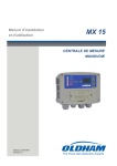
The MX15 control unit consists of the following components:
• A wall case with access «hatch» to settings (potentiometers)
• A motherboard including all system components (power supply, display, relays and
connectors
• A front face with tactile keys.
II.
Technical specifications
1.
Characteristics
Mounting
Box on DIN rail or wall mount
Dimensions:
185 * 157 * 67 mm
Materials:
ABS type plastic
Cable inputs/outputs:
3 cable gland type M20 cable diameter 5.5 to 12 mm
1 cable gland M16: diameter 4 to 8 mm
direct input available through wall crossing
Protection:
IP31
Electric power supply
230 VAC or 115VAC upon request
and 24 VDC
Consumed power:
16 VA
Operating conditions
Ambient temperature:
-10 to +45°C
Storage temperature:
-10 to +40°C
Humidity:
5% to 95% non-condensed
Embedded audible alarm:
through buzzer
7
Number of measuring channels
1
Number of sensors:
*1 OLC10-type combustible gas detector or 2 OLC10 TWIN
detectors for detection of methane, butane, propane in boiler
rooms and GPL, GNV or H2 in parking lots
*1 OLCT10-type combustible gas detector for detection of
methane, butane, propane in boiler rooms and GPL, GNV or H2
in parking lots
*1 to 5 detectors of same type OLCT10 for detection of CO,
NO, NO2.
Cable length:
OLC10 and OLC10 TWIN: max. 300 m at 3x1.5 mm²
(4x1.5 mm² between the two OLC10 TWIN) OLCT10 EXPLO:
1,000 m at 1.5 mm²
OLCT10 TOX: 2,000 m at 1.5 mm²
Sensor reading:
continuous
Measuring ranges
programmable
Display
front
Type:
LCD screen
4 digits 7 segments, 3 characters 14 icon segments
4 LEDs
Description of unit and gas: programmable by user in a list
3 characters edited by user
Keyboard:
through tactile keys for access to menus, indicator test,
acknowledgment
Alarms
Type:
2 independent thresholds defined by user
manual or automatic erasure by increasing or decreasing value
through programming
viewing through red indicator
relay output (alarm 1 and 2)
Relays
2 independent alarm relays with positive/negative safety
programmable by manufacturer.
1 out of order relay in positive safety
break or make contact that may be configured on all relays using
a jumper
Cutoff level
2A / 250 Volts AC/ 30 volts DC
8
Connection
Type:
Cable section:
spring terminals
maximum 2.5 mm²
Remote acknowledgment
through short circuit of 2 MX15 terminals, using an
external potential-free dry contact (maximum 2 meters)
Certification
ATEX 94/9/CE Directive:
category (3)G for metrology in combustible gas detection EN
61779-1 and 4 in zones 2.
Low-voltage directive:
in accordance with EN 61010
Electromagnetic Compatibility
Directive CEM:
in accordance with EN 50270
III.
Detail specifications for use in Combustible
Atmospheres in accordance with the ATEX
94/9/CE European Directive
The MX15 detection control unit, designed for measurement of combustible gas, is
compliant with the requirements of the ATEX 94/9/CE European Directive regarding combustible
atmospheres.
Thanks to its metrological performance, the MX15 control unit, associated with the
INDUSTRIAL SCIENTIFIC CEX300 and OLC 10 detectors, is a safety device for ATEX Zone 2
classified areas. The control unit can also reduce the risk of explosion through information
provided to external units.
The site manager where the equipment is installed should take into consideration and
comply with the information in the following paragraphs. Refer to the provisions of the ATEX
1999/92/CE European Directive regarding the enhancement of safety and health of the workers
exposed to risks of combustible atmospheres.
1.
Specifications
for
mechanical
installation in Classified Zone
and
electrical
Installation will be performed in accordance with existing standards, in particular, EN
60079-14, EN 60079-17 standards.
The MX15 control unit should not be exposed to mechanical vibrations and should be
installed in a safe area, away from combustible atmospheres.
It is essential to refer to the operating and start-up instructions of the above-mentioned gas
detectors in paragraph ‘Detail specifications for use in combustible atmospheres in accordance with
the ATEX 94/9/CE European Directive.’
9
2.
Metrological Specifications
The control unit complies with the metrological European standards EN61779 and
EN61779-4 for methane (calibration gas), butane, propane and hydrogen (gas as per response
curves), when the control unit is used with CEX300 and OLC 10 gas detectors.
In the event that the control unit is used with other types of sensors supplying a measuring
current of 4/20 mA, they should comply with paragraph 1.5 of Appendix II of the Atex 94/9/CE
Directive and be compatible with their characteristics (see control unit transfer curve).
Note: the test vibrations in accordance with EN61779-4 paragraph 4.13 have not been performed
because they do not apply due to the operating conditions of the MX15 control unit.
3.
Connection of detectors other than
SCIENTIFIC to the MX15 control unit
INDUSTRIAL
As previously explained, the user who wants to connect detectors other than INDUSTRIAL
SCIENTIFIC, should ensure that they are compatible with the control unit so that the unit is
considered a safety device.
3.1. Transfer curves of control unit in configuration 0 at 100% LEL
The following curve provides a response to the control unit regarding the measured value
and fault processing, based on the value of the input current supplied by the detector. In the event
that the user connects a detector of a brand other than INDUSTRIAL SCIENTIFIC to the MX15
control unit, he/she should ensure that the transfer curve is compatible with the input characteristics
of the control unit, so that the information provided by the detector is accurately interpreted. In
addition, the control unit should supply a sufficient supply voltage taking into account the cable
drops.
Display
in % LEL
SUP
Fault
100 % LEL
0 % LEL
-15 % LEL
Fault
1.6 4
mA mA
20
mA
Signal supplied by
the detector in mA
Caution: When the sensor reading is >= to 100% LEL, the measuring unit memorizes this scale
overrun; the channel passes to alarm and fault mode. The resetting of this status is manual and is
the responsibility of the user who should comply with the safety instructions of his/her site. The
10
resetting is either validated through an ON/OFF of the control unit or through a maintenance
operation.
3.2. Power supply and load resistance characteristics
Maximum current available between terminals 2 and 3: 300 mA at 20 V.
Maximum no load voltage between terminals 2 and 3: 30 V
Load resistance between terminals 1 and 2: 47 ohms
4.
Marking
INDUSTRIAL SCIENTIFIC Arras[a1]
II (3) G
OSA 05ATEX0120
IV.
Control unit installation
1.
Control unit mounting
Mounting is performed using a DIN rail, positioned so that it provides a 5 cm free area around the
control unit.
The MX15 control should be installed in all facilities away from combustible atmospheres,
preferably in a monitored area (control center, consol room, control room, etc.) and in a less humid
(no condensation) and temperate environment (see chapters 2.1 and 3)
2.
Control unit electrical connections
Electrical connections should:
- be performed by a specialist and while the control unit is off (power supply is shut off)
- comply with existing regulations (including NF C 15-100)
- has a minimum section of 1.5 mm² and a maximum section of 2.5 mm2 for power supply
from power system (230VAC)
Check the current nature and network voltage (the network voltage should match the voltage
specified on the control unit maker’s plate).
2.1. Protective ground
The control unit must be connected to an operating ground. The ground terminal (yellow ochre) is
identified by the following symbol:
Refer to wiring examples at the end of the manual.
11
2.2. Power supply
2.2.1.
Power supply 230 Volts (115VAC on request)
230VAC is standard power supply: protection is provided
-
either through F8= 630 mA/250VAC
either through F6/F7 = 100 mA/250VAC
F8
A special “115VAC” configuration is provided by the manufacturer upon request.
The control unit should be protected upstream through a bipolar differential circuit breaker.
The response curve is of type D.
The mains should be wired on the two terminals L (orange) and N (blue), as indicated in the wiring
examples at the end of manual.
2.2.2.
Power supply 24 VDC (protection through F8) can be connected on
terminals COM and +24V, as indicated in the wiring examples at the end
of the manual.
2.3. Connections
2.3.1.
Sensors
The various types of sensors should be connected on the terminals C1, C2 and C3 (white) of the
connector as indicated in the wiring examples at the end of manual.
The "Wheatstone bridge"-type "combustible gas " sensors with 3 active wires:
C1:
C2:
C3:
median point (signal)
detector filament (-)
compensator filament (+)
12
Sensors/transmitters 4/20 mA with 2 active wires :
C1:
C2:
C3:
signal (current return to ground)
not connected
positive power supply (+24 Volts)
Sensors/transmitters 4/20 mA with 3 active wires :
C1:
C2:
C3:
signal (current return to ground)
power supply COM
positive power supply +24 Volts
1. For each sensor family, the manufacturer will insert a programming support (Explo 340mA
or 4 -20mA) to the circuit: see above figure.
2. Note: if several OLCT10 toxic sensors are connected (maximum 5), programming of the
electronic circuit is required, which should be performed by an authorized person.
**Jumpers for Connecting Multiple Sensors:
1-sensor = no jumper required
2-sensors = jumper J-28
3-sensors = jumper J-28, J-27
4-sensors = jumper J-28, J-27, J-29
5-sensors = jumper J-28, J-27, J-29, J-30
2.3.2.
Alarm relays
The MX 15 control unit has two alarm relays corresponding to two pre-programmed instant alarm
thresholds.
The relays are in positive safety (negative upon request) and potential-free.
REL1 terminals match the relay 1 contacts (alarm 1).
REL2 terminals match the relay 2 contacts (alarm 2).
The relay contacts can be used “normally open or closed” moving the appropriate jumper (next to
relays)
The relay contacts are potential-free.
Refer to the wiring examples at the end of manual.
2.3.3.
Fault relays
The fault relay is in positive safety.
The DEF terminals match the fault relay contacts (fault).
The relay contacts can be used “normally open or closed” moving the appropriate jumper (next to
the relay)
The relay contacts are potential-free.
13
Refer to the wiring examples at the end of the manual.
2.3.4.
Remote acknowledgment
A pushbutton for “remote acknowledgment” may be connected to the MX15 control unit to the
“acknowledgment” terminals (dry and potential-free contacts) at a maximum 2-meter distance.
Refer to the wiring examples at the end of manual.
VI.
1.
Operating instructions
Instructions on the display upon activation:
Upon activation of the control unit a list of information is automatically displayed on the display
unit: software version, maintenance access code, pre-programmed alarm thresholds, stabilization
time sheet, etc. and then the sensor reading continuously supplied by the sensor.
1.1. Measuring channel display
The MX 15 control unit continuously displays the sensor reading; however, by simultaneously
pressing the + and – keys of the front keyboard, the sensor reading will be replaced with an
interrupted line on the display unit.
To return to the sensor reading display, press one of the two keys, + or - .
To return to normal operation, simultaneously press the + and – keys.
2.
Menus
Reminder: for safety purposes, only authorized and trained individuals are
permitted to use the following menus.
2.1. Menu viewing
To exit the normal operating mode and access the menu list, use the front keyboard:
-
press the MENU key
use + / - and ENTER keys, validate the standard access code « 1000 »
use + or – key to view the available menus, such as:
PROGRAMMING (PRG)
USI (factory calibration) *
INITIALIZATION (INI)
CODE (COD)
BUZZER (BUZ)
TEST (TST)
14
* the USI menu is not detailed below because it is only reserved for the manufacturer:
never use it without previous training!
** * *
2.2. Menu Selection
-
display the desired menu as indicated in the previous chapter
select this menu by pressing the ENTER key
2.3. To exit while viewing a menu (ECHAP)
Simultaneously press the + and - keys and then confirm/reject the saving of potentially modified
parameters:
-
press ENTER to abort without any change
press «+», then ENTER to exit and save the changes.
2.4. Programming menu
A maintenance symbol
•
is displayed while using the programming menu.
This allows programming of parameters of the measuring channel such as:
-
-
On/off: yellow DEL is blinking
Detected gas chemical symbol (CH4 /CO, etc.)
Measuring unit (%LEL/ppm, etc.)
Measuring scale and decimal point (0.1/1.0/10/100/1000, etc.)
To program two gas alarm thresholds (characteristics): corresponding red DEL is on during
this step
To select the erasure type of gas alarms:
1.
manual (MAN) = if the gas concentration again becomes lower than the
preset alarm threshold, this alarm must be acknowledged manually by
pressing the acknowledgment key
2.
or automatic (AUT) = if the gas concentration again becomes lower than
the preset alarm threshold, the acknowledgment is automatic.
Timing (in minutes and seconds) of the alarm relay activation time: yellow DEL is blinking
MA
Diagram of alarm activation
Exceeding alarm
threshold
-
DEL
Alarm
and Buzzer
Timing
AL relay
cutover
Timing (in minutes and seconds) of the fault relay activation time: yellow DEL is on
continuously
Timing of the control unit upon activation (relays disabled): yellow DEL is blinking and the
following icon
is displayed.
15
-
-
-
To indicate the type of sensor used, such as:
• Bridge: in bridge (filaments), types OLC10, CEX300, etc.
• EHP: EXPLO (explo. 4/20mA), type OLCT10, etc.
• InC: fire (ionic, optical, etc.)
• O2: oxygen
• Aut: other (toxic, etc.)
To change the maintenance mode, MAN or AUT:
- AUT: Detection of detector calibration mode of this function (yellow DEL blinking
on MX15)
- MAN: No detection of detector calibration mode
Timing (in minutes and seconds) upon exit of «calibration» menu (relays disabled)
To save potentially modified parameters in this menu (yes or no):
-
If “NO” validated: the changes are not taken into contact
If “YES” validated: the new programming will be saved.
2.5. Initialization menu (INI)- Start-up
This menu is used to INITIALIZE the microprocessor based on the connected sensor
It is used in the following cases:
- by INDUSTRIAL SCIENTIFIC when new equipment is shipped
- during the first installation
- during a cell or sensor replacement
2.6. Code (access) menu
This menu changes the access code for various menus (1000 in standard upon shipment of
equipment):
-
display the CODE menu (+ and – key)
select it (enter)
display current code
indicate the new code using the + and – keys
save this new code (enter)
finally confirm it (yes/no/enter)
2.7. Buzzer menu
Allows or does not allow the use of the buzzer embedded to the MX15 control unit:
-
display the BUZZER menu (+ and – keys)
select it (enter)
select ON (active buzzer) or OFF (buzzer off)
finally confirm (yes/no/enter)
2.8. TEST menu (TST)
Disables the relays embedded to MX15 upon voluntary activation of alarms through injection of a
standard gas on the sensor to test the alarms or to calibrate:
-
display the TST menu (+ and – keys)
select it (enter): yellow DEL is blinking
16
-
yellow DEL is blinking, the TST message and the
the relays are disabled during the test or calibration
key are displayed, confirming that
Attention: this menu should be used for calibration after a first start-up.
INDUSTRIAL SCIENTIFIC recommends:
Gas detection instruments are potential life-saving devices. Recognizing this fact, Industrial
Scientific Corporation recommends that a functional (“bump”) test be performed on fixed gasmonitoring instruments as part of a regular maintenance program. A functional test is defined as a
brief exposure of the monitor to a concentration of gas(es) in excess of the lowest alarm set-point
for each sensor for the purpose of verifying sensor and alarm operation and is not intended to be a
measure of the accuracy of the instrument.
Industrial Scientific recommends that a full calibration be performed using a certified
concentration(s) of calibration gas(es) quarterly, every 3 months.* Calibrations may be necessary
more or less frequently based, for example, on application, field conditions, exposure to gas, sensor
technology, and environmental conditions. The frequency of calibration is best determined by
company policy or local regulatory agencies. Please refer to the instrument user manual for specific
details.
If an instrument fails to operate properly during any functional “bump” test or if an instrument
experiences an alarm condition, a full instrument calibration should be performed.
These recommendations are based on safe work procedures, industry best practices,
and regulatory standards to ensure worker safety. Industrial Scientific is not responsible for setting
safety practices and policies.
*
For new installations it may be prudent to carry out bump tests frequently at first
(perhaps weekly), increasing the time intervals (to, perhaps, monthly or more) as
confidence grows with experience in the installation concerned, on the basis of the
maintenance record.
Reminder: for safety purposes, only authorized and trained individuals are
permitted to use the following menus.
Procedure to be followed when the MX15 control unit is connected to an combustible gas
sensor
(OLC10/CEX300, etc.):
-
the TEST menu was selected (see above)
remove the small cover on the front of MX15 to access the setting potentiometers
adjust, if needed, the ZERO (read the display unit) using a zero potentiometer «O»
Reminder: make sure that you have clean air - otherwise inject air or nitrogen into the sensor
(with calibration kit) with a flow rate of 60 l/h, then wait for the sensor reading to stabilize.
17
-
Now inject the standard gas (60l/h) into the sensor and wait for the sensor reading to
stabilize
Make sure that the gas concentration is correct by reading the display unit
Otherwise, adjust the sensitivity using a “S” potentiometer
Disconnect the standard gas cylinder
Wait for the “return to zero” on the display unit
Press the TEST key to exit this menu
The yellow “DEL” is off and the display unit indicates an interrupted line
Press one of the two keys + or – to display the sensor reading, if needed
Position the small cover in place.
Procedure to be followed when a MX15 control unit is connected to a transmitter 4-20 mA
without a local maintenance device (calibration position switch, etc.) :
-
-
3.
Select the TEST menu to disable the relays of the control unit: see the beginning of this
chapter
Adjust the transmitter (see manual of relevant product)
Make sure that the transmitter instructions (O and S) match those of the control unit. Refine
the adjustments, if needed, of the control unit and, in this case, refer to the previous
paragraph
Upon completion of calibration, wait for the «return to zero» on the display unit of the
control unit
Press the TEST key to exit this menu
Yellow “DEL” is off and the display unit shows an interrupted line
Press one of the two keys + or – to display the sensor reading, if needed.
TESTING of rela ys and externa l controls
It is also recommended to periodically check alarm activation and the corresponding external
controls.
4.
Cleaning
Do not use alcohol or ammonia-based liquids to clean the control unit.
If needed, clean the outside of the case with a damp cloth.
5.
Control unit maintenance
The control unit does not require special maintenance.
If sensor calibration is required, this operation should only be performed by qualified personnel.
•
REFER TO CHAPTERS 4.2.5 AND 4.2.8 (INITIALIZATION AND TEST)
•
Do not forget to initialize the system upon sensor replacement: use the “INI” menu
(chapter 4.2.5).
6.
Replacement of fuses
Fuse replacement should be performed only by qualified personnel.
18
List and type of fuses used in the MX15 control unit: the fuses used should comply with CEI 127,
should be timed and have a low cutoff power.
VII. Spare parts
-
Fuse 630 mA/ref. 6154627
Full electronic map/ref. 6451569
Potentiometer cover/ref. 6123711
Cover retention screw /ref. 6902569
Equipped ready front cover (self-adhesive front panel, small cover mounted, 4 screws)/ref.
6323648
19
VIII. Examples of connections
JUMPER
L N T
MAINS
230VAC
DEF
RL1
COM
RL2
+24V
Remote acknowledgment
1
relay contact outputs:
potential-free
NO or NF based on position of
jumpers next to relays.
3
Connector of first sensor
with 2 wires.
MX15 CONTROL UNIT
1
3
31 31
31 31
31 31
IN
OUT
IN
Example of connection between a MX15
20 control unit and two OLCT10-type
sensors for detection of the same gas (maximum 5 sensors) .
JUMPER
L N T
DEF
MAINS
230VAC
RL1
COM
+24V
RL2
Remote acknowledgment
relay contact outputs:
potential-free
NO or NF based on position of
jumpers next to relays.
1 2 3
Connector of first sensor
with 3 active wires.
MX15 CONTROL UNIT
1 2
3
1
2
1 2 3 41 2 3 4
OUT
IN
Example of connection between a MX15 control unit and
two OLC10 TWIN-type sensors.
21
1234
OUT
1234
IN
jumper
L N T
DEF
MAINS
230VAC
RL1
COM
+24V
RL2
Remote
acknowledgment
relay contact outputs:
potential-free
NO or NF based on position of
jumpers next to relays.
1 2 3
Connector of sensor
with 3 active wires.
1
1
2
2
3
3
Connect the 3 wires based on
numbering
Example of connection with an EXPLO 22
or TOXIC sensor with 3 active wires.
OLDHAM ITALIA S.R.L.
Italia
℡ (39) 011 38 013 71
(39) 011 38 066 13
[email protected]
23